Transcription
Installation GuideWendland Mk5 Roof System1
Thank you for choosing the Wendland roof system.This guide is designed to make fitting as straightforward as possible.Before you commence installation of the roof, please;1)Take a moment to read these two introductory pages2)Do not fix the frames down at this stage – onlybefore reading the rest of this guide.temporarily ‘pin’ the frames to the house wall (one fixingeach side) to allow the conservatory to ‘float’.Wendland have been making conservatories since 1995.We have continued to invest to improve the features that thehomeowner will appreciate and that should make your lifeeasier. Any feedback - positive or negative - is welcomed sowe can make our systems even better.Please contact the Tech Support Teamon 01200 452 318 or n 1section 2section 3section 4section 5section 6Pre-installation checksRoof vent sashEdwardian roof installationTie barsRoof vent installationBox gutter installationBox gutter jointingBox gutter supportsection 7section 8section 9section 10section 11section 12section 132Box gutter raised backValleysLean-to installationGable installationHip lean-to installationMuntin bar installation & Capping removalGutter Cover installationInternal Pelmet installation456-1212-1314151616-171718-191920- 21212223- 2728- 55ALL box gutters (especially thosewith tie bars or joints) MUST besupported.We recommend several types ofsupport for box gutters includingbrick piers. See pages 22-23 fordetails of our solutions. Fitting aconservatory box gutter withoutadequate support will lead tostructural failure. Please take thecorrect steps BEFORE installation.
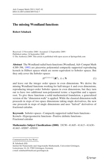
TOOLS REQUIRED10 & 13mmSocket SpannerDeadblowHammer or WhiteRubber MalletNo. 2 Pozi-drive Bit5mm Wide FlatBlade ScrewdriverHack SawDrill/ScrewdriverLong nose pliarsGasket Shears/Snips4.5mm Drill BitSealant Gun2 x 5mm AllenKeys (Vic fixing kit)17mm OpenEnded Spanner Tie BarsSpirit LevelTape MeasureAnglefinderPlumb bobEaves to frame fixings, host wall fixings and ridge top cap flashing trim screw not supplied.General pointsProductby the homeowner, as surfaces may be scratched if not handledinstallation guide. The location plan is used to match individualCare should be taken when handling components that are seenwith care. Choose a suitable area for unpacking the componentsand always check them before fitting. Any claims for missing ordamaged parts are only accepted in line with our standard termsand conditions of sale.Health & safetySite safety is paramount. The Construction (Design & Management)Regulations 2015 apply to the whole construction process, onall construction projects from concept through to completion.Compliance is required to ensure construction projects areThe roof kit is supplied with a location plan, part check list and thiscomponents to their respective position on the roof. Our numberingconvention always starts at the top left, against the house wall asyou look from outside the conservatory back at the host wall.The majority of aluminium and PVCu components containidentification codes, usually by inkjetting or labelling – should youneed to re-order a part this should help. Please ask for a copy ofour product guide to keep in the van, which will give you furtherassistance with future identification.carried out in a way that secures health and safety. The installationSealingteam, the customer and members of the public.1. For roofs glazed with Polycarbonate (or standard sealed units)company shall be responsible for the safety of all of the fittingThe Surveyor should have carried out a risk assessment to reducerisk on site and this should have been discussed with you prior tostarting.It is important to use the correct sealant when sealing the roof.a low modulus neutral cure brand of silicone must be used2. For roofs glazed with Conservaglass or other true ‘self cleaning’glass, then MS Polymer sealant such as Rotabond 2000 must beused.Please use safe working platforms and ladders that comply withSealed Unitsrecommendations. Personal Protective Equipment – such asFor the correct selection of sealant please see aboveBS EN 131. Always use equipment in line with manufacturersgoggles, mask and ear defenders – should be used when, forAll protective handling tape must be removed prior to installation.example, grinding out for the flashing.The SuperstructureCareful consideration should be given to the safe disposal of allall frames which abut the host wall are vertically plumb, which willpackaging – our packaging is predominantly made from recycledmaterials and can be readily recycled.Check the Dwarf wall or Plinth for being level all round. Ensure thatthen allow perfect alignment with our eavesbeam. Before startingto install the roof, please check the condition of the host walland whether it’s plumb – depending upon what you find, theseconditions can seriously affect the final integrity of the roof.3
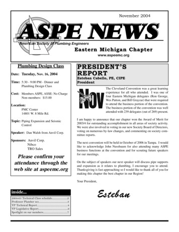
SECTION 1PRE INSTALLATION CHECKSUnpack the roof vent sash and assemble, see section 2. If possible, do thisin the factory the day before.At this stage do not fix the frames down - pin only to the house wall (onefix per side) to allow the conservatory to ‘float’.Take the glazing bars from the roof pack and check the anchor clips arefitted (the clips are always at the top of the slope). On the eaves beamcheck that there are the correct amount of twin and single bolts and thatthe glazing support trim is fitted.Attach the glazing bar end cap fixing blocks - as access restrictions (boxgutter situations) may prevent easy attachment later.Check the condition of the host wall as this may affect the quality of the final installation. Check the host wall is plumb - any running in/or out should havebeen accounted for by the surveyor. If not, the ridge and starter bars may require packing out with aluminium shims. Correct alignment in this area is criticalto a successful installation - Plumb frames/level ridge.Only use the specified fixings - never be tempted to substitute alternative sizes/gauges.MS Polymer- Conservaglass- Self cleaning glassUse the correct sealant4Low modulusneutral cure- Polycarbonate glazing- Standard sealed units
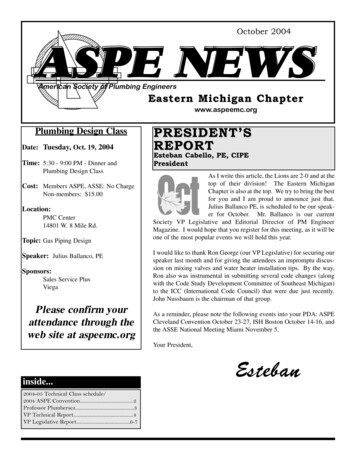
SECTION 2ROOF VENT SASH122am70mUnwrap the sash and pull two side sections Apply length of foam tape directly to the loweredge of the outer pane of the glass unit asout as shown above.shown. Start by applying the tape 70mm upRemove any protective handling tape around the side of the glass unit and continuing towrap around the lower edge of the glass unit,the perimeter of the unit prior to installation. finishing 70mm up the opposite side.33a31For pitches below 10 it is recommended thatthe glass is sealed in by running a bead ofsilicone along the length of each sash sectionas shown above. For pitches above 10 it isadvisable to do the same.3b24Once tape has been applied, assemble thesash in the sequence shown above andensure the tape is directed against section 2.4If the pre-drilled holes appear out of alighment The two sections can then be readjustedas shown above in red simply slacken off the so they are in line and square. Then the nonfactory fitted screws.factory fitted screws can be fixed down.4a*NOTE* The roof vent has beensuccessfully tested by the BBA at 25 upto 1200Pa without sealant.Finally re-fasten the factory fitted screws.On the hinge side of the sash fill the holeshown above at either end with a blob ofsilicone.5
SECTION 3EDWARDIAN INSTALLATIONFITTER TIP - VIC FIXINGKIT60mm frames70mm framesIn lineWhen using the Victorian Fixing Kit drill a 10mm hole through the base of the eaves beam and completely through the head of the window frame. Ensurethat both sides of the 10mm hole are accessible for Allen key fixing. Use a 5mm Allen Key to tighten the fixings. The eaves beam should be fixed at 450mmcentres and within 200mm of each corner. THIS IS THE RECOMMENDED FIXING METHOD123UnderguttertrimApply a continuous bead of silicone to the frontand rear inner legs of the window frames.Fit the initial piece of eaves beam ensuring thatthe inside face of the eaves beam is flush withthe inside face of the window frame.Please note: Ensure that the under guttertrim is fitted to the eaves beam and all boltsare in situ prior to fixing to the frames.4Place the next section of eaves beam intoposition, by slotting the corner cleat on theadjacent piece of eaves beam into the first piece.5Using the pre-drilled pilot holes, drill two 4.5mmholes through the corner cleats.6200mmSecurely fit the two M5 x 12mm taptite screws.6Securely fit the eaves beam to the frames usingfor example, 38mm x 4.8mm screws in theposition shown. Fix down at 450 centres andwithin 200mm of each corner. For 60mm framesuse the inner eaves extrusion line and outerline for 70mm frames. Always screw down. (Notsupplied)Once the eaves beam is secure, run a bead ofsilicone down the joint where the eaves beamsections meet and where the eaves abuts thehost wall.
SECTION 3EDWARDIAN INSTALLATION7Support the ridge at the host wall and crownpoint. Ensure the spider has been pre drilled,glazing fascia and glazing pocket have beenfitted.Fitters Tip: Pre-stress the ridge by supportingit 10mm higher than specified at the crownpoint.10Continue to support the ridge and offer up thestarter bars at the host wall.Locate on to the single bolts at the ridge andeaves.13Secure with flanged nuts at ridge and eaves.8Offer up the first hip bar to the spider, insert thelocation pin through the spider arm fixed to thehip. Locate the pin into the pre drilled relevanthole on the spider.11Secure with flanged nuts at ridge and eaves.14Using the location plan, repeat these stepsuntil all rafters that meet the ridge have beenfitted in the correct position and have beensecured.9Locate the hip onto the bolts at the eaves.Loosely secure with flanged nuts.Repeat these steps until all hip andintermediate bars that meet the spider, havebeen positioned.12Continue to support the ridge and offer up therafters that meet the ridge.Locate onto the double bolts at the ridge andbolts at the eaves.15Fitting the jack rafters, ensure the jack rafterbrackets have been fitted to the jack rafter priorto installation.7
SECTION 3EDWARDIAN INSTALLATION16Offer up the jack rafter on to the hip and locateon the bolts at the eaves.The jack rafter bracket should be angledtowards the specified hip18Once fixed, minor adjustment maybe required toalign the undercladding flush with the under sideof the hip, this can be done by adjusting the boltsto suit.Repeat these steps until all jack raftersare fitted. Fully secure all rafters andhips.21Fit all the gutter brackets supplied with the kitat maximum 750mm centres and maximum200mm from each corner.817aAlign the bracket with the pre drilled holes on thehip bar, pass two M6 x 20mm through the holesand secure with flanged nuts.19Next, build on the ground the gutter runs, byrolling items like a stop end under the back edgeof a gutter jointer. Push up to the insertion line.DO NOT silicone seal, this would prevent naturalexpansion contraction.22Locate the back edge of each section of gutterinto the slot in the gutter bracket.17bIf two jack rafters are aligned either side ofthe hip, a M6 x 25mm bolt is required to fixboth sets of brackets through either side.20Snap the integral clips on the adaptors over thegutter. IMPORTANT: ensure all lengths of gutterfit to the market insertion line seen in all unionsand box gutter adaptors.2324Clip the front of the bracket into the lip onthe gutter. PVCu components like the gutterare easier to manipulate when warm. In coldconditions more ‘force’ may be required.
SECTION 3EDWARDIAN INSTALLATION24Ensure all gutter runs have been fitted and thatall glazing bars are fully secured.27Check that the pitch of the roof is correct. YourSurveyor should have provided a drawing/a copyof the roof confirmation which displays the pitch.30Drill through the holes on the ridge fixing bracketand secure with the correct masonry anchor.Now fasten the frames to the host wall andthe dwarf wall.25Check the window frames are plumb.28Check that the starter bar and first transom barsare parallel.31Tighten the grub screws on the spider arms tofully secure the hips at the spider.(Minor adjustment can be done using thegrub screws if hip bars are slightly uneven)26Ensure the ridge is level.29Drill the starter bars/masonry within 200mmof the ridge and eaves beam plus at least onemore equidistant between the two. Pack out tosupport the starter bar behind each fixing beforefitting the correct masonry anchor.32Fit the spider arm covers with the glazing sealsinserted.9
SECTION 3EDWARDIAN INSTALLATION333435Now glaze the side framesbefore glazing the roof this provides additionalrigidity whilst workingabove. INSTALL TIE BARS(S)BEFORE GLAZING.Take the glazing end profile and run continuousbead of sealant (appropriate for glazing)immediately behind the co-extruded gasket(along the full length). Now seal the spacebetween the glazing end profile and the sealedunit (see inset) at each end (DO NOT DO THIS ONPOLY ROOFS).36Snap off a gromet from the kit, this will slot overthe upstand on the glazing stop.Repeat spets 35 & 36 for all glazing bars onthe roof.37Tease the ‘tail’ of the glazing support trim tapefree (ready to be pulled away when the sealedunit is finally in position).Snap off appropriate handed glazing stop.Place this into the base of the glazing bar.38At the is point the roof should be glazed.Any ridge support may be removed.Insert the glazing between the rafters ensuringthat it is centralised.If you are installing a roof ventplease refer to page 1439Ensure the glazing stop is pressed tightly upagainst the end profile. When in position use thefixings provided to fix the glazing stop down intothe bar as shown.Ensure clip offers maximum support toglazing at all times.1040Once the roof has been fully glazed and glazingstops secured, work your way around the roof fitting the glazing bar top caps. These should beangled in at the ridge first before forcing the topcap down along the bar length.Ensure to fully engage anchor clip41Knock the glazing bar top cappings on with aDeadblow hammer. Greater care is needed incold weather. Keep all trims wrapped while fittingfor protection.
SECTION 3EDWARDIAN INSTALLATION42If you haven’t fitted already, attach end cap fixingbrackets.Fit the glazing bar end caps by sliding onto theend cap brackets. Push fit the insert into the endcap.45Take the semicircular foam piece and insert itinto the front of the crown point.This may require sculpting to suit thesituation.48Fit the ridge top cap complete with flashing trimand crown cap to the ridge.43When fitting the jack rafter top caps, seal wherethe cap meets the hip top cap. The jack rafter topcap should sit tightly against the hip cap.46Now fit the ridge flashing trim to the ridge topcap, apply a bead of silicone inside to secure.49If cresting is specified, insert the cresting downthe channel on the ridge top cap. This mayrequire trimming to suit.44Once all the to caps have been fitted, insert thesquare foam block into the top of the crownpoint.47Apply a generous amount of sealant to the backedge of the flashing trim.50The finial should sit over the crown point whencresting is fully inserted.11
SECTION 3EDWARDIAN INSTALLATION50Moving inside the roof, fit the ridge undercladdingto the ridge.5330 25 20 51Insert the nylon threaded bar into the bottom ofthe spider.5452Offer up the internal radius end cap, use thethreaded bar and the retaining boss to securethe internal cap in position.The threaded bar may require cutting to suit.5515 The internal radius end capping may requiretrimming to suit pitch (pitch lines are marked onthe reverse of the internal radius end capping).Fit the internal fascia claddings to the eavesbeam, ensure the fascia corner packers areattached on the inside of the fascia at eachcorner.Fit the corner covers by trapping them behindthe fascia sections. Insert the circular infill tofinish.TIE BAR INSTALLATIONWhen a tie bar is specified, it is a structuralrequirement & must be fitted.SECTION 41a2aPrior to starting installation check the ridgeis level and the side frames are plumb. THISIS CRITICAL TO THE SUCCESS OF THEOVERALL INSTALLATION.The position of the tie bar (s) will be indicatedon the location plan provided whilst the tiebar brackets are already attached to theglazing bars.750 7507507503000714 71412Staggered jack raftersUse this designwhen a tie bar andceiling fan clash - twovertical drop rods.Tie bar at finialInsert the tie steel rod thread into the base of thespider. Measure the drop of the rod and cut tosuit the position or the tie bar boss ring.Offer up the internal radius end cap, retain thisusing the tie bar ridge fixing cover and two selftapping screws provided. Cut the PVCu conduitto suit.
SECTION 4TIE BAR INSTALLATION1bTie bar at ridgeMark the position of the where the tie bar meetsthe ridge, fix the ridge fixing cover using the selftapping screws provided.4Insert the smaller diameter pieces of PVCuconduit inside. Offer into the boss ring and fingertighten the nyloc nut.7Now, finally check that the horizontal elementsare level and the vertical element is plumb.CHECK THAT THE SIDE FRAMES ARE STILLPLUMB. Spanner tighten the boss nyloc nuts.2bThread the tie bar rod into the ridge fixing cover.Measure the drop of the rod and cut to suit theposition or the tie bar boss ring.5Offer up the horizontal pieces of PVCu conduit(large and small diameter).8Offer up the two part rose cover, spin one halfonto the threaded end of the other half.3Measure, cut and attach the horizontal threadedbars (ensure sufficient engagement of the barinto the brackets) – it is essential that the tie barboss is central. Take the boss ring, and looselyassemble the threaded bars to check theyterminate inside the ring. Dis-assemble.6Insert threaded bar into the ring, and again fingertighten the nyloc nuts.9Attach the bracket cover plates that hide thebolts.13
SECTION 5ROOF VENT INSTALLATION56Peel back any protective film prior to fitting. Fit upper glazed unit andinternal muntin bar. Carefully lower the vent frame into position ontothe internal upper muntin bar.6aIf existing glazing is 32/35mm a packer willhave been pre-fitted to the frame.97Run a bead of appropriate sealant ensuringa continuous run along the external uppermuntin bar. Please see section view for beadpositioning.9aSlide the internal lower muntin bar into placeunder the vent frame. See cross section 9a forfurther detail.11Run a bead of appropriate sealant ensuringa continuous run along the external lowermuntin bar. Please see cross section for beadpositioning.Ensure the vent is central between the transoms. As shown abovethere should be a 13mm gap between the bar centre and the frame.Use glazing packers if necessary.128Locate the external upper muntin bar withthe internal muntin bar, knock into place. Thelower muntin may need to be supported fromunderneath whilst secure into final position.10Remove any handling tape around theperimeter of the unit. Take care lowering theglazed unit into position on the internal lowermuntin bar.13When the sealant on the mainframe has cured,Locate the external lower muntin bar with the re-fit the outer sash by holding vertically andinternal lower muntin bar, knock into place. re-engage on to the hinge, before lowering intoThe lower muntin may need supporting from position.underneath whilst secured into final postion.For more installation information, please refer to the roof vent installation guide which is supplied with the roof vent.14
BOX GUTTER INSTALLATION1Box gutter foam to be cut back 70mm toenable the box gutter to sit flush on the frames.Apply a continuous bead of appropriate sealantto the front and inner legs of the window frames.Lift insulated box gutter into position – ensure ithas adequate support whilst fitting.42Place eaves beam section – with underguttertrim attached – onto the side frames. Seal thejoint between the eaves beam and box gutter.5SECTION 63Whilst ensuring that its level, drill through theback edge of the aluminium at 600mm centres.Bolt to the house wall using masonry anchorsthat are suitable for the substrate.6Either peel back or knife off a small amount ofthe insulation where the cleat is to be fixed. Drilla 4.5mm pilot hole and then fix the cleats withthe two M5 12mm taptite screws provided. Theprotruding taptite screws will need trimming backprior to fixing the adaptor ( alternatively, when itstime to insert the adaptor, undue the taptites,drill a pilot hole through the adaptor and then rescrew the taptites and fully seal).Mark out and grind a channel in the masonry forthe flashing – blow out any dust in the channel.Now, from the bag in which the adaptor issupplied, take the special tube of sealant,Gutterbond. Apply a generous bead of it evenlyacross the mouth of the box gutter, 20mm backfrom the front edge.Slide the adaptor into the aluminium boxgutter, raising up its front edge to utilise theunique snow plough effect. This spreads theGutterbond evenly under the adaptor. Push theadaptor firmly up to its end stop, so that it will linethrough with the Classic gutter attached to theeaves beam.With the adaptor tight to the end stop, turn thetoggles upwards to firmly press the adaptor intothe Gutterbond.Seal the top and bottom edges of the aluminiumbox gutter, where it abuts the house wall.Before lifting into position, assemble thefascia board and undercladding. Offer up theundercladding rear legs, and knock up intoposition. Lastly locate the upper legs of thefascia board on to the box gutter. Finally seal theundercladding against the house wall.710Use the balance of the Gutterbond to back pointany gaps at the front edge.811Now seal the internal joint between the eavesbeam and box gutter and back point the leadingedge of the box gutter where it sits on theside frames. Knife off a small section of theundergutter trim in preparation for the insertionof the adaptor.9IN ADVERSE WEATHER CONDITIONS FIT THEADAPTOR TO THE BOXGUTTER PRIOR TOLIFTING THE BOXGUTTER INTO POSITION1215
SECTION 6BOX GUTTER JOINTING1Thoroughly clean the mating parts using wirewool. Surfaces must be clean and grease free.Apply a generous bead of low modulus neutralcure to the pre-fixed internal sleeve along theentire face of the sleeve.423Drill through the top edge of the aluminiumbox gutter at 600mm centres .A fixing must bepositioned within 50mm each side of the joint.Offer second half of the box gutter up to theinternal sleeve and push firmly on. Fasten thissecond box gutter run to the host wall withmasonry anchors suitable to the substrate.Ensure both sections are level and flush.5Drill 6.5mm holes through the box gutter andsleeve (at positions shown, ensuring both halvesof the box gutter are flush together) and fix usingthe bolts, nuts and washers provided and in theorder shown . Trim any excess off the bolt headbefore fitting the internal cladding as it may foul.ALL box gutters (especiallythose with tie bars or joints)MUST be supported.We recommend several types of supportfor box gutters including brick piers.Fitting a conservatory box gutter withoutadequate support will lead to structuralfailure. Please take the correct stepsBEFORE installation.Check surfaces are dry, clean and grease free.De-grease if necessary.Heat both the sealing tape and the box gutterwith a heat gun and position the tape over thejoint. Press the tape firmly across the joint of thesleeve and the box gutter ensuring there are noair pockets.Now seal over all the exposed bolt heads, onthe inside and outside of the box gutter.BOX GUTTER SUPPORTBOX GUTTER STRAP165mm box guttersThese are supplied loose and MUST BE FITTED – they are a structural requirement of the roof. Thestraps must be installed within 75mm of glazing bar centres (when measured from centre of thestrap to the centre of the bar). To install these straps, simply nip up as shown.265mm/special box guttersStraps are factory welded into position.GALLOWS BRACKETThese are available for 165/265 box gutters.To install, notch out the insulation to ensure metal to metal contact between the extruded box gutterand gallows bracket. Offer up the gallows bracket and mark it ready to drill – always try to line up withthe centre of a brick rather than a mortar joint. Drill the gallows bracket (the positions should be similarto the ones shown). Three masonry anchors should be used that are appropriate to the substrate.Finally, notch out the undercladding, offer it into position and clip in.16Maximum centres are 2300mm. If the roof has a tie bar installed or a joint within the box gutter,then a gallows bracket should be installed directly underneath it.
SECTION 6BOX GUTTER SUPPORTBOX GUTTER HANGER165mm box guttersIf these have been specified by your company at the time of order they are supplied loose and mustbe fitted.The structural requirement for the hanging brackets are 2 x hanging brackets (sat side byside) at a maximum span of 2300mm unless the roof has a tie bar or joint on the box gutterwhich should then be positioned in the same area.Drill through the head of the hanger into the centre of the masonry, avoiding the mortar joint ifpossible. Use a masonry anchor suitable for the substrate. Lead flashing should be dressed downover the hanger, and snipped around the sloped leg. To attach it to the box gutter, simply ‘nip up’ asshown.265mm box guttersHanger not available.RAISED BACK BOX GUTTERS1Offer the raised back or special box gutter intoposition. Carefully mark onto the aluminium legagainst the host wall the position of each fixing –use 600mm maximum centres.4Remove the box gutterand drill the host wallwhere marked. Grindout the course whichis at least one coursehigher than the raisedback height.2Lift the box gutter down to the ground and turnit around. Drill through the aluminium leg (thatabuts the host wall) at the pre-marked positions.Whilst the box gutter is on the ground, sealalong the front/rear face where the deep skirtsits inside the head of the extruded box gutter.(Highlighted in red)5Offer the box gutter into position and insertthe anchor fixings that are appropriate for thesubstrate and tighten up.3Lift the box gutter back into position, checklevels, and then mark the wall (through the predrilled holes) ready to drill the host wall and grindout for the flashing.6Seal the top and bottom edges of the box gutterand follow all other steps as per standard boxgutters on page 20-23. When installing the leadflashing, ensure that the top of the flashing ishigher than the point of rain water dischargefrom the glazing bars. Clad off the deep skirt ofthe raised back box gutter using multi –board(not supplied).17
SECTION 7VALLEY INSTALLATIONETCH SHEET FORMAT, ISSUE 21AUTHOR3Ensure the two ridges are at the correct heightand are level. Make sure bolts at the ridge andeaves have been fitted to accept the valley.ALL DESIGN & OTHER INFORMATION IS CONFIDENTIAL TO & THEPROPERTY OF ULTRAFRAME (UK) LTD. ALL DESIGN RIGHT, COPYRIGHT& OTHER INTELLECTUAL PROPERTY RIGHTS IN & TO THE DESIGNS &INFORMATION & ANY CHANGES THERE TO & DEVELOPMENTS THEREOF BY ULTRAFRAME OR ANY THIRD PARTIES ARE OWNED BY AND/ORASSIGNED TO ULTRAFRAME COMPLETELY.ENTERPRISE WORKS, SALTHILL Rd, CLITHEROE, LANCASHIRE, BB7 1PEDRAWN BY:DESCRIPTION:DRAWING No:MODEL NAME: / CONFIG. NAME:Cut and re-fit the glazing support trim, where thevalley meets the eaves beam.7Fit the double sided sealing tape to each of thevalley wings. Tease one end of the protectivetape loose, crease it about 50mm in from the endand fold over ready to extract once the glazingpanels are laid in position.18REV.2At the stage where all other bars have beenfitted and secured to the roof and the ridge andhalf ridge have been fixed to the wall, the valleyassembly should be fitted.4CHANGE No.CAD MODEL IS MASTER5SCALE:1:1Draw1DATE CREATED:Offer up the aluminium valley section, ensuringthe under cladding location barbs are slid intoposition. Locate onto the captivated bolts in theridge, half ridge and eaves beam. Secure thevalley using the 4 spigot nuts provided in thevalley end cap kit.16/11/2017STATUS:STOCK CODE:REV: PRP:"Revision"SHEET 1 OF 1, SIZE A316/11/2017Now run a continuous bead of suitable siliconedown the entire length of the aluminium valleyprofile, at the point of the hinged connector inthe centre.8To retain the glazing to the valley wing, fit 2 wireclips (100mm from each end of the profile). Thehooks locate behind the lip detail as shown.Apply a continuous bead of sealant (MS Polymerto self cleaning glass).6Using the location plan provided, assemble thevarious valley rafters onto the valley. Use thewashers and nuts provided to ensure a robustjoint is created.249Place the glazing in its correct position. Positionthe end profile down into the valley as shown.With the glazing pressed flat against the valleyprofile and your fingers underneath, pull theglazing up into the rain baffle and allow the clipto ‘lock’ the glazing in place. Once properly fitted,the clip should lock into place as shown.
SECTION 7VALLEY INSTALLATION101112ly of the low pitch lean-to ridgethat the correct number of rafter/ridge fixing plates are fitted to the ridge.re and mark up the position of the ridge.t the ridgeposition.Fit the valley end cap using the two plastic rivetsFitinthevalley top cladding by folding to form anyou are satisfiedridgeleveldrillthrough theridge atsuppliedthe V- or appropriate fixings.internal that‘V - thethentap isintothealuminiumvalleyinto the profilehost wall.using a plastic hammer.the ridge to the wall with appropriate fixings for the host wall. Check withpplier for information on fixings for different walls.ssary use packing behind the screws if the host wall is not even.LEAN-TO INSTALLATION1Fix the Fig.ridgeat the specified height to the wall,7.2. Fixing the low pitch lean-to ridgedrill through the v groo
Wendland have been making conservatories since 1995. We have continued to invest to improve the features that the homeowner will appreciate and that should make your life easier. Any feedback - positive or negative - is welcomed so we can make our systems even better. Please contact the Tech Support Team on 01200 452 318 or email