Transcription
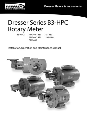
Dresser Meters & InstrumentsDresser Series B3-HPCRotary 0Installation, Operation and Maintenance Manual
ContentsLimited Warranty 3Receiving, Handling and Storage 4Introduction 4 Use and Limitations 4 Operating Principle 4General Descriptions 5Series B3 HPC Meters 5Meter Installations 5 Piping Configurations 5 Placing Meter in Line 7 Meter Start-up 8Accessory Unit 9 Reading the Odometer 9 Imperial Odometer 9 Metric Odometer 9 Maintenance for the Series 3 Accessory 10 Counter (CTR) Version 10 Removing the Accessory Unit 10 Installing the Accessory Unit 11 Removing the Gear Reduction Unit 12Accessory Unit (continued) 9 Replacing the Gear Reduction Unit 12 Counter with Instrument Drive (CD) 12 Instrument Drive Side Inlet to Top Inlet Conversion 12 Changing the Instrument Drive Rotational Direction 15 Installing a Solid State Pulser 16 Counter with Electronic Transmitter (ICEX) 16 Installing an ICEX 16Series B3-HPC Cartridge Replacement and Changeout Kit 17 Differential Test 17 Establishing Baseline Curves 18 Differential Test Procedure 19 Proving Operations 19Trouble Shooting Checklist 202
Limited WarrantySeller warrants that Products shall be delivered free from defects in material, workmanship and title and that Services shall be performed in acompetent, diligent manner in accordance with any mutually agreed specifications. The warranty for Products shall expire one (1) year from first useor eighteen (18) months from delivery, whichever occurs first, except that software is warranted for ninety (90) days from delivery. The warranty forServices shall expire one (1) year after performance of the Service, except that software-related Services are warranted for ninety (90) days. If Productsor Services do not meet the above warranties, Buyer shall promptly notify Seller in writing prior to expiration of the warranty period. Seller shall (i) atits option, repair or replace defective Products and (ii) re-perform defective Services. If despite Seller’s reasonable efforts, a non-conforming Productcannot be repaired or replaced, or non-conforming Services cannot be re-performed, Seller shall refund or credit monies paid by Buyer for suchnon-conforming Products and Services. Warranty repair, replacement or re-performance by Seller shall not extend or renew the applicable warrantyperiod. Buyer shall obtain Seller’s agreement on the specifications of any tests it plans to conduct to determine whether a non-conformance exists.Buyer shall bear the costs of access for Seller’s remedial warranty efforts (including removal and replacement of systems, structures or other parts ofBuyer’s facility), de-installation, decontamination, re-installation and transportation of defective Products to Seller and back to Buyer. The warrantiesand remedies are conditioned upon (a) proper storage, installation, use, operation, and maintenance of Products, (b) Buyer keeping accurate andcomplete records of operation and maintenance during the warranty period and providing Seller access to those records, and (c) modification orrepair of Products or Services only as authorized by Seller in writing. Failure to meet any such conditions renders the warranty null and void. Selleris not responsible for normal wear and tear. The above sets forth the exclusive remedies for all claims based on failure of or defect in Products orServices, regardless of when the failure or defect arises, and whether a claim, however described, is based on contract, warranty, indemnity, tort/extra-contractual liability (including negligence), strict liability or otherwise. The warranties provided above are exclusive and are in lieu of all otherwarranties, conditions and guarantees whether written, oral, implied or statutory. NO IMPLIED OR STATUTORY WARRANTY, OR WARRANTY ORCONDITION OF MERCHANTABILITY OR FITNESS FOR A PARTICULAR PURPOSE APPLIES.3
At Time of Delivery1. Check the packing list to account for all items received.2. Inspect each item for damage.3. Record any visible damage or shortages on thedelivery record. File a claim with the carrier. Notify your Dresser meter supplier immediately.Do not accept any shipment that has evidenceof mishandling in transit without making animmediate inspection of package for damage. Allnew meters should be checked for free rotationsoon after arrival as damage to internal workingparts can exist without obvious external evidence.Should any serious problems be encountered duringinstallation or initial operation of the meter, notify yourDresser meter supplier immediately.Do not attempt repairs or adjustments, as doing somay be a basis for voiding all claims for warranty.When reporting a suspected problem, please provide thefollowing information: Your Purchase Order Number and/orDresser’s Sales Order Number The Meter Model, Serial Number and Bill ofMaterial Number(This information can be located on the blue name platethat is between the differential plugs on the meter body) The Accessory Unit Serial Number A Description of the problem Application information, such as gas type, pressure,temperature, and flow characteristicsOur Product Services Department offers professionalservices for all Dresser Natural Gas Solutions (NGS)products. Authorization for return is required for allproducts shipped to the Factory for repair, calibration,warranty, exchange or credit. To obtain authorizationan RMA number for return of Dresser products must beissued. Please contact your Dresser meter supplier. Allreturns should be packaged in an original-type shippingcontainer if available or shipping material that will protectthe product. Note: Do not use peanut packing foambecause fragments may enter the measuring chamber.Storage/Initial TestingIf the meter is not tested or installed soon after receipt,store in a dry location in the original shipping containerfor protection. Make sure the box remains horizontal withthe arrow pointing up. Leave the protective caps installedin the meter. The caps will provide reasonable protectionagainst dust.4“Checking for free rotation” (Refer Figure 12) does notnecessarily mean the meter will pass a test after sitting onthe shelf for a year or two. A small amount of oil is appliedto the bearings of new or remanufactured meters, but thisis only sufficient for factory testing. The oil in the bearingscan coagulate over time. This condition may impact metertest performance until the bearings loosen up. Dresserrecommends a drop or two of oil be applied to eachbearing and that the meter be run at a flow rate between80% & 100% of meter capacity for two minutes or untilthe meter is running smoothly.IntroductionUse and LimitationsDresser meters are suitable for handling most types of clean,dry, common gases at either constant or varying flow rates.The meter is not suitable for handling liquids. Measurementaccuracy and life expectancy may be affected by dirt orother types of foreign material in the gas stream. For a list ofacceptable dry gases, consult factory.Meters of standard construction are not suitable forhandling acetylene, biogas or sewage gas. Speciallyconstructed meters compatible with these and othergases are available. Please contact your Dresser metersupplier for details and to request publication TS:SSM.Operating PrincipleAs shown in Figure 1, two contra-rotating impellers oftwo-lobe or “figure 8” contour are encased within a rigidmeasuring chamber, with inlet and outlet connectionson opposite sides. Precision machined timing gearskeep the impellers in correct relative position. Optimaloperating clearances between the impellers, cylinder, andheadplates provide a continuous, non-contacting seal.Figure 1 - Impellers rotating inside meter cylinderBecause of this design, the gas at the meter’s inlet iseffectively isolated from the gas at the outlet. Duringimpeller rotation, the precision machined measuringchamber traps a known volume of gas between theimpeller and the adjacent cylinder wall. The meter willmeasure and pass four equal gas volumes with eachcomplete revolution of the impellers.The sum total of the four volumes is the “volume perrevolution”. The volume is indicated in Engineering unitsrepresented in cubic feet (or cubic meters). Volumetricaccuracy of the Dresser meter is permanent and nonadjustable. Measurement characteristics are establishedby the shape and the precise machining of non-wearingfixed and rotating parts.
A meter’s rated capacity is the maximum flow rate atwhich the meter may be operated and is determinedby the dynamic loads acting on the moving parts of themeter. These loads are primarily related to meter RPM, andsecondarily to the metering pressure. The standard volumecapacity of a rotary meter increases directly with changesin absolute line pressure and inversely with changes inabsolute line temperature.General DescriptionDresser meters are manufactured in accordancewith the American National Standard specification ANSI/ASC-B109.3 for Rotary Type Gas Displacement Meters.The flanged inlet and outlet connections conformdimensionally to ANSI/ASME standard B16.5. The operatingtemperature range is from -40 F to 140 F(-40 C to 60 C).Every meter pressure vessel is static pressure tested atthe factory at 200% its Maximum Allowable OperatingPressure (MAOP) and leak tested at 125 percent of MAOPin accordance with the ASME Boiler and Pressure VesselCodes. All aluminum parts of the cartridge (i.e., impellers,measurement chamber, and headplates) are hard-coatanodized for added corrosion and abrasion resistance.Cleansing and lubrication for the main bearings and timinggears is provided by a “splash” lubrication system. Bothends of the cartridge case on the Series B3-HPC meterserve as oil reservoirs. Oil slingers located at either end ofthe meter cartridge distribute oil for lubrication.The same 1M and 3M cartridges will fit into eitherthe 740 psig MAOP housing or the 1480 psig MAOPhousing. The 1M and 3M cartridges share a commoncast-steel housing as do the 5M and 7M cartridges.The 11M cartridge fits into its own housing and does notshare a housing with another meter. In all casesthe measurement cartridge assembly slides into thehousing. Measurement cartridges are field replaceableand can be interchanged between the common housings.An optional, full flow internal bypass and/or optionalbypass indicator are available on all HPC meters and/or measurement cartridges. The bypass valve versioncartridges are interchangeable with the non-bypass valveversion cartridges.Meter InstallationsPiping ConfigurationsSeries B3-HPC meters can be installed in either a Top Inlet(vertical gas flow down) or a Side Inlet (horizontal) pipelineconfiguration as shown in Figures 2 and 3 respectively. Thepreferred or recommended installation is top inlet in a verticalpipeline with gas flowing downward. Although the designof the impellers tends to make the meter inherently selfcleaning, top inlet mounting enhances the likelihood that dirt,pipe scale, or other debris will pass through the meter.Piping should be rigid and properly aligned. The meterdoes not require any direct means of support, but thepiping on either side should be supported to eliminate anyunnecessary piping strains on the meter case.Accuracy is not affected by low or varying line pressures.Series B3-HPC meters may be used satisfactorily forpressures ranging from a few ounces to full MAOP. Themeter base rating is expressed in Actual Cubic Feet perHour (ACFH), or in Actual Cubic Meters per Hour (Am3H).A good practice is to install the meter in a side loop witha bypass adjacent to the main line. Also, the installationof tees upstream and downstream of the meter will helpfacilitate transfer proving with the meter still mounted inthe line.Displaced volume measurement is completelyindependent of the gas specific gravity, temperature, andpressure. Volume measurements can be easily convertedto Standard conditions by application of the Basic or IdealGas Laws for elevated pressure and varying temperature.Do not install the meter lower than the discharge pipe run,in order to avoid accumulation of condensate and foreignmaterials in the metering chamber. Use a Dresser GasketStrainer, Dresser Pipeline Strainer, or other type strainerupstream of the meter to help remove foreign matter (pipesealant, tape, weld slag, etc.) from the gas stream. A 100Mesh screen is recommended for the strainer.IMPORTANT: The maximum working pressure of a rotarymeter is limited by casing design. Meters should not beinstalled where line pressure can exceed the MAOP. Referto the pressure vessel nameplate for the MAOP.Series B3-HPC MetersThe 1M and 3M High Pressure Cartridge (HPC) meters areavailable with a 740 psig (51Bar) rating with ANSI Class 300#flanges or 1480 psig (102Bar) rating with ANSI Class 600#flanges. The 5M, 7M and 11M meters are only available witha 1480 MAOP rating and ANSI Class 600# flanges.The installation of a lubricated gas valve directly before ameter is not recommended, as excess valve lubricant orother foreign material may stop impeller rotation.To help prevent over-speed conditions from occurring, arestricting flow orifice plate is shipped with each HPC meterand it should be installed 2 to 4 pipe diameters downstreamof the meter. Orifice plates are included with all B3-HPC highpressure meter shipments at no additional cost.NOTE: Warranty does not cover meter failure due toover-speed conditions.5
StrainerIsolating ValvesRestricting FlowOrifice Plate1/4" Blow-offValve1/4" NeedleValveInletOutletFigure 2 -Top Inlet Configuration for Series B3 HPC MeterStrainerRestricting FlowOrifice PlateIsolatingValves1/4" Blow-offValve1/4" NeedleValveInletFigure 3 -Side Inlet Configuration for Series B3 HPC Meter6Outlet
Placing Meter In Line1. Before installing a meter: Make sure the upstream piping is clean. Duringthis procedure, use extreme caution and followrecommended company procedures. Ensure the plastic protective caps have beenremoved from both meter flanges prior tometer installation. Ensure the impellers turn freely and no objectsor contaminants are in the measuring chamber.2. Meter Orientation: Connect meter inlet to the gas supply side of the line,ensuring the gas flow will be in the same direction asthe arrow on the meter body nameplate (i.e., arrowpointing downward for Top Inlet).3. Install the meter without piping strain. Use pipe supportsas required. Level all meters to within 1/16” per runningfoot (5 mm/m), side-to-side and front-to-back.4. Tighten flange bolts or stud nuts evenly in a crosspattern. The maximum recommended torques 80 footpounds (108 Newton-Meters) for all HPC Meters.CAUTION: The meter must NOT be under pressurefor this procedure.5. After the meter is installed, remove the socket headplug in the timing gear end of the meter (as shownin Figure 4) using a hex wrench. Insert a Hex wrenchinto the timing gear clamp on the end of the impellershaft and slowly turn the impellers clockwise, checkingfor free rotation. If binding is present, do not attemptto disengage the impellers. Remove the meter fromthe set and clear all obstructions or piping strain priorto reinstallation. Replace the plug after verifying freeimpeller rotation and torque to 9.5 to 10.5 ft. lbs(12,9-14,2 Newton-Meters).AccessPlugFigure 4 - Remove the access plug to check impeller rotation.6. Oil is shipped with each new meter in a quantitysufficient to fill the meter body reservoirs in either aTop Inlet or a Side Inlet configuration. Slowly add oil tothe meter body end reservoir until the oil level is to thecenter of the oil gauge (sight glass) as shown in Figure5. Refer to Figure 6 for oil fill/drain plugs and sight glasslocations. DO NOT OVERFILL.Table 1 - Oil CapacitiesMeter SizeSide InletTop InletIM740/14804.2 oz. (124 ml)11 oz. (325 ml)3M740/3M14802.8 oz. (83 ml)7.2 oz. (213 ml)5M148018 oz. (532 ml)37 oz. (1094 ml)7M148014 oz. (414 ml)29 oz. (858 ml)11M148014 oz. (414 ml)34 oz. (1006 ml)CL1/8CLCL3mmSTART OIL LEVELADD OILFigure 5 - Fill oil reservoirs to mid level of sight glassNOTE: The meter oil fill plug is located on the gear endside. This meter has oil reservoirs in both ends connectedby an oil path tube. Please allow time for the oil to traversethe oil path tube and fill the counter end reservoir beforeassuming the meter is full of oil.CAUTION: Perform a Leak Test immediately afterplacing meter back in service. Refer to meter Start-Upprocedures, below. All leak pointsmust be eliminated quicklybefore leaving the meter site.Otherwise, remove the meterfrom service by placing onbypass or another method.IMPORTANT: DO NOT add oil tothe permanently lubricated Series 3Accessory Unit.CAUTION: THE METER ENDCOVER IS PRESSURIZED.Bleed off the line pressurebefore removing the oil fill ordrain plugs from the meter.7
Series B3-HPC 1M and 3MSeries B3-HPC 11MOil Fill/Drain PlugsTop InletOutletInletOil Sight GaugesOil Sight GaugesSeries B3-HPC 5M and 7MInletInletOil Fill PlugsOutetOil Drain PlugOil Sight GaugesDrainPlugOil SightGaugesDrainPlugOil Sight GaugesSide InletFigure 6 - Oil fill/drain plugs and oil level sight gauge locationsMeter Start-Up1. Slowly pressurize the meter in accordance with thefollowing recommendations:IMPORTANT: Do not exceed 5 psig/second (35 kPa/second)maximum when pressurizing. Rapid pressurization cancause an over-speed condition which may damage themeter. Resulting damage is not covered by warranty.a) Open the bypass and outlet (downstream of meter)gas valves.b) P artially open the meter inlet gas valve until themeter starts operating at low speed. Throttling thebypass valve may be necessary to initiate gas flowthrough the meter. Verify gas is flowing through themeter by watching for movement of the black-andwhite RPM wheel on the Accessory Unit. The wheel,shown in Figure 7, is visible from either the front orthe side of the polycarbonate cover on a standardcounter meter. If movement is present, go to step.c). If the RPM dial is not turning, verify gas is beingdelivered to the meter. If gas is flowing to the meterinlet and the RPM wheel is not moving, go to step f).Figure 7 - Movement of the RPM wheel indicates impellerrotation.d) Let the meter operate at low speed for severalminutes. Listen closely for unusual scraping orknocking sounds.e) If operation is satisfactory, go directly to step g).8
f) If unusual sounds are present or the accessory unit’sRPM wheel is not turning, place the meter in bypass.Slowly depressurize and vent all pressure from themeter set before checking for problems. (Releasepressure at a rate less than 5 psig/second.) Once theproblem is resolved, repeat the start-up procedurebeginning with step a).DANGER: Slowly depressurize and vent all pressurefrom the meter set before working on meter.g) Gradually open the inlet valve until full line flow ispassing through the meter and the inlet valve isfully open.h) Slowly close the bypass valve.i) Follow your company’s authorized procedures orcommon industry practices to leak test the meterand all connections. Soapy water, Snoop , and gasanalyzers are commonly used for this procedure.Snoop is a registered trademark of the Swagelok Company.Meters installed and maintained in accordance with factoryrecommendations can be expected to operate dependablyfor many years. Proper oil level and cleanliness have thegreatest effect on meter life expectancy. Visually inspect theoil reservoir for proper mid-gauge oil level once a monthuntil a practical interval is determined. Add oil as necessary.NOTE: On all sizes of the IMC/W2 accessory unit pressureand temperature connectors must be external.For instructions in installing the IMC/W2 on the HPC meter,request customer Installation InstructionsPN 056684-000.Reading the OdometerImperial odometersThe 1M through 11M odometers with Imperial units ofmeasure have five exposed digits. As an industry standard,the first digit on the left of the odometer is typicallyconcealed with an opaque mask. Translucent masks arenormally specified to cover the two right-most digits. Theodometers for 1M and 7M meters are shown in Figure 8.When reading the odometer, the exposed digits betweenthe arrows are typically multiplied by 100 to read thevolume in hundreds of cubic feet. For example, a readingof 2576 would be read as 257,600 cubic feet. If the lasttwo digits to the right of the arrows were included in thereading, and those numbers were 83, the reading wouldthen be 257,683 cubic feet.Oil change frequency will depend upon the cleanliness ofthe gas being measured. Change oil when the color darkensor when the level increases, indicating an accumulation offoreign liquids. Under favorable conditions, these periodsmay be from 3 to 5 years, or longer.MODEL 1MRATIO 675:1DO NOT add oil to the Series 3 Accessory Unit.No scheduled lubrication maintenance is required.Accessary UnitTotalization of the volume is performed by a magneticallycoupled gear reduction unit referred to as the Series 3Accessory Unit. These units are permanently lubricated forlong life and maintenance-free operation. They registerdisplaced volume in actual cubic feet (ACF) or actual cubicmeters (Am3). The Series 3 Accessory Unit is isolated fromthe pressure vessel and is not pressurized. This modulardesign allows interchangeability of Accessory Units onSeries B meter bodies of the same size.The HPC meters are available with both mechanical andelectronic accessory units. The Dresser Micro Corrector,Model IMC/W2, can be mounted integrally to the 1Mthrough 11M size meters. For those customers that requirethe 11M1480 with metric readout, the electronic accessorymodel IMC/W2 is the only available option.MODEL 7MRATIO 160:1Figure 8 - Non-Compensated Series 3 Imperial unit odometerfor 1M (Top) and 7M (Bottom).NOTE: Some customers special order Accessory Unitswith a multiplication factor of 1000. Refer to the markingbetween the arrows on the Accessory Unit nameplate forverification of the multiplier used, i.e. “Reading X 100 Cu.Ft.”, or “Reading X 1000 Cu. Ft.”Metric odometersAll 8 digits are exposed on the Metric odometer. On the1M and 3M metric meters, the portion of the faceplatesurrounding the last two digits to the right is typicallyprinted black and a decimal point (comma) is shown justbefore the printing. The area between the arrows is read ascubic meters. For example, a reading of 202597 betweenthe arrows would be read as 202597 cubic meters. Ifreading all 8 of the digits, a reading of 202597,39 wouldthen translate to 202597 cubic meters plus a fractionalreading of 0,39 cubic meters.9
On the 5M and 7M metric meters, the portion of thefaceplate surrounding the last digit to the right is printedblack and a decimal point (comma) is shown just beforethe printing. Again, the reading between the arrows is readas cubic meters. Therefore, a reading of 1592432,7 wouldtranslate to 1592432 cubic meters plus a fractional readingof 0,7 cubic meters. Examples of metric odometers areshown in Figure 9.MODEL 1MRATIO 238.235:1Figure 10 - Series 3 Accessories do not require oil.(CTR Version shown)Counter (CTR) VersionMODEL 7MRATIO 564.904:1Figure 9 - Non-Compensated Series 3 Metric Unit odometers for1M (Top), 5M (Bottom)A test wheel is located on the right side of the odometer.The graduated increments on the test wheel represent 0.2cubic feet. This allows for accurately estimated readingsof 0.1 cubic feet. White reflective marks are located to theleft of the graduated increments for prover testing withan optical scanner. For metric versions, the graduatedincrements on the test wheel represent 0,002 cubic metersfor the 1M and 3M meters, and 0,02 cubic meters for the5M and 7M meters. This allows for accurately estimatingreadings of 0,001 cubic meters and 0,01 cubic metersrespectively.NOTE: The 11 M is not available in a metric version.NOTE: On both Imperial and Metric versions, the highspeed, black-and-white proving wheel attached to the endof the RPM drive shaft is visible either from the front orthe end of the accessory and can be used for verificationof unit operation and meter testing. Refer to “ProvingOperations.” The wheel is also shown in Figure 7 in the“Meter Start-Up” section.Maintenance for the Series 3 AccessoryThe CTR, CD, ICEX, and Solid State Pulser do not requirescheduled maintenance. To clean the polycarbonatecover, use warm water and soap, mineral spirits, isopropylalcohol, or cleaning products approved for use onpolycarbonate materialImportant: Aromatics, Ketones, and Chlorinatedhydrocarbons will damage the polycarbonate cover.The Series 3 CTR units register displaced volume in actualcubic feet (ACF) or actual cubic meters (m3) on an 8 digitodometer. The Series 3 CTR cover is molded of opticalquality polycarbonate with a quad ring seal. The cover’ssmooth cylindrical design easily sheds rain and resistsaccumulations of snow, ice and dirt.NOTE: Reference the “Reading the Odometer” sectionfor instructions on reading the Series 3 Accessory Unit.Removing the Accessory Unit from the MeterThese general procedures require the following toolsand equipment: 5/32” Hex wrench 9/64” Hex wrench A light grade of machine oil, grease or petroleumjelly for lubricating o-rings. Adjustable torque wrench with a range of 5-40 in-lbs.Use the 5/32” hex wrench to remove the four #10-24screws holding the slip flange on the meter end cover.(Refer to Figure 14). Loosen the screws in a cross or star-likepattern.Remove the accessory unit by carefully pulling thecomplete assembly directly away from the meter body,taking care not to damage the male driving magnet on theaccessory gear train. Remove the O-ring from the meterend cover, if applicable. Verify which type of o-ring seal isbeing used on the accessory unit before replacing.NOTE: The newer polycarbonate cover will have the quadseal O-ring installed in the polycarbonate cover. If the quado-ring comes loose from the groove in the polycarbonatecover, clean the cover and O-ring with isopropyl alcoholbefore attempting to replace the O-ring.For detailed information on removing/installing theaccessory unit, request document 053939-000 for CTR,ICEX or Pulser versions or 054429-000 for CD version.10
Installing the Accessory Unit on the MeterProperly align the male driving magnet with the magnetcup in the meter body. (Refer to Figure 11).While holding the Accessory Unit in place, slide the slipflange over the Polycarbonate cover. Rotate the slip flangeuntil all four holes in the slip flange are aligned with thefour screw holes in the meter end cover. A dimple in thenon-instrument drive version slip flange should be closelyaligned with the odometer.While holding the slip flange to the meter end cover,insert the four #10-24 screws into position and tighten ina cross or star-like pattern to 20-25 in.-lb. (47-53 in-lbs. forCD version) When properly installed, the slip flange willbe in continuous contact with the meter end cover. Fordetailed information on removing/installing the accessoryunit, request document 053939-000 for CTR, ICEX or Pulserversions or 054429-000 for CD version.If applicable, follow company procedures for installingtamper-evident security devices.Gas FlowQuad SealMeter End CoverLexan CoverMagnet CupSlip FlangeMale Driving MagnetOdometer(s)Facing Outward#10-24 Screws (4x)Figure 11 -Assembling Series 3 Accessory to meter end cover.11
Removing the Gear Reduction Assembly from thePolycarbonate CoverReplacing the Gear Reduction Unit inPolycarbonate CoverUse a 9/64” hex wrench to remove the mounting screwholding the accessory unit in the polycarbonate cover.The screw can be accessed through the Tool Access Port asshown in Figure 12.1. Slide the gear reduction unit into the polycarbonatecover. Align the odometer with the large, clear windowon the cover. When the gear reduction unit isproperly installed, the pin that is molded into thebottom of the polycarbonate cover will engage a holein the bottom of the plate. (Refer to Figure 12)Slide the gear reduction unit out of the polycarbonate cover.2. Using a 9/64” hex wrench, insert the screw into thethreaded boss on the polycarbonate cover and torqueto 20-25 in.-lb. Do not over tighten to avoid damage tothe threaded boss.Polycarbonate CoverGear Reduction UnitMounting ScrewTool Access PortFigure 12 - Exploded view of Gear Reduction Assembly and Polycarbonate CoverCounter with Instrument Drive (CD) VersionInstrument Drive Side Inlet to Top Inlet ConversionThe Counter with Instrument Drive (CD) unit utilizesthe CTR gear reduction assembly, a specially designedpolycarbonate cover, and an Instrument Drive supportassembly. The Instrument Drive (ID) support is mechanicallylinked to the gear reduction of the CTR unit and drives theinstrument ‘drive dog’ at the ID output. One revolutionof the instrument drive dog represents 10CF for imperialmeters (0,1M3 for Metric meters).The following procedures are required to change theorientation of the instrument drive assembly. Refer toFigures 13 and 14 for component locations.NOTE: Lubrication is not required for the ID support housing.12NOTE: Regardless of the meter being mounted in eithera Side Inlet or Top Inlet orientation, the Instrument DriveAccessory must always remain in a vertical (or upright)position during operation. Refer to the “Meter Installation- Piping Configurations” section of this manual for propermeter mounting practices.
1. Use a flat blade (slotted) screwdriver to remove thetwo #1/4-20 screws holding the Universal InstrumentAdapter Plate to the ID support assembly.2. Using a 5/32” hex wrench, remove the four #10-24screws holding the neck of the ID Support Assembly tothe ID Housing.3. Using a 5/32” hex wrench, remove the two #10-24screws holding the Side Cover Plate onto the IDhousing. Remove the cover plate.4. Install the ID support assembly in the vertical mountingposition (where the cover plate was removed). Torquethe screws to 40 in.-lb.5.
Dresser Series B3-HPC Rotary Meter B3-HPC: 1M740/1480 3M740/1480 5M1480 7M1480 11M1480 Installation, Operation and Maintenance Manual. 2 Contents Limited Warranty 3 Receiving, Handling and Storage 4 Introduction 4 Use and Limitations 4 Operating Principle 4