Transcription
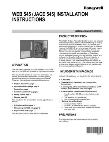
WEB 545 (JACE 545) INSTALLATIONINSTRUCTIONSINSTALLATION INSTRUCTIONSPRODUCT DESCRIPTIONAPPLICATIONThis document covers the mounting, installation and initialstart-up of the WEB-545. It applies to the following products:This document is targeted at engineers, technicians, andservice personnel who are involved in control systeminstallation and start-up using the Niagara Framework .These are the main topics included in this document: Product Description, page 1 Included in this Package, page 1The WEB-545 (Java Application Control Engine) is a compactembedded processor platform with Flash Memory for backup.The platform provides integrated control, supervision, andlegacy device integration. When connected over an Ethernetnetwork, the WEB-545 can communicate with power meters,gas meters, water meters, as well as legacy devices, Londevices, and BACnet systems using a variety of optionalcommunications drivers. A complete set of Java-basedcontrol, application, logging, and user interface “objects” areincluded in a library for the Energy Systems Integrator tocreate a robust monitor and control system for any sizebuilding. With the User Interface option (factory ordered asWC2003B 2004, WEB-545-UI), it can directly serve live dataand dynamic displays over the Internet to any standard webbrowser such as Internet Explorer.INCLUDED IN THIS PACKAGEIncluded in this package you should find the following items: A WEB-545. These WEB-545 Installation and ConfigurationInstructions, Precautions, page 1 A packing slip, which lists the factory settings for IPaddress, machine name, and host logon. Installation and Start-up, page 2 A hardware bag containing the following items: Wiring Details, page 7 Figures, page 10Also included in this document are several appendixes, asfollows: Using Status LEDs, page 12 Maintaining the WEB-545, page 12 Replacement Parts, page 13This document does not cover station configuration.—Four 3-position RS-485 screw terminal connectorplugs.— Two wire nuts (US models only).— One 2-position LON connector plug Optional items (if ordered)———Factory-installed modem.RJ-45 to DB-9 adapter (for the RS-232 port).Silver satin patch cable (used between the adapterand serial port).PRECAUTIONSThis document uses the following warning and cautionconventions:95-7710
WEB 545 (JACE 545) INSTALLATION INSTRUCTIONSCAUTIONCAUTIONCautions remind the reader to be careful. Theyalert readers to situations where there is a chancethat the reader might perform an action thatcannot be undone, might receive unexpectedresults, or might lose data. Cautions contain anexplanation of why the action is potentiallyproblematic.Work in a static-free area.Discharge any static electricity you may haveaccumulated. Discharge static electricity by touching aknown, securely grounded object.Do not handle the printed circuit board (PCB) withoutproper protection against static discharge. Use a wriststrap when handling PCBs, with the wrist strap clampsecured to earth ground.WARNINGWarnings alert the reader to proceed with extremecare. They alert readers to situations where thereis a chance that the reader might do somethingthat can result in personal injury or equipmentdamage. Warnings contain an explanation of whythe action is potentially dangerous.SAFETY PRECAUTIONSThe following items are warnings of a general nature relatingto the installation and start-up of the WEB-545 controller. Besure to heed these warnings to prevent personal injury orequipment damage.INSTALLATION AND START-UPThere are four major steps to installing and starting the WEB545, as outlined below:1. Unpack the WEB-545.2. Install the WEB-545.3. Upgrade, License, and Configure the Host.4. Install the Station Database and Start the Station.Please read through the entire document before beginning theinstallation procedure.Unpack the WEB-545WARNINGUnpack the WEB-545 and inspect the contents of the packagefor damaged or missing components. If damaged, notify theappropriate carrier at once and return any damagedcomponents for immediate repair or replacement.A 120Vac (US models) or 100Vac (Internationalmodels) circuit powers the WEB-545 controller.Disconnect power before installation or servicing toprevent electrical shock or equipment damage.Install the WEB-545Make all connections in accordance with national andlocal electrical codes. Use copper conductors only.To reduce the risk of fire or electrical shock, install in acontrolled environment relatively free of contaminants.This device is only intended for use as a monitoringand control device. To prevent data loss or equipmentdamage, do not use it for any other purpose.Static Discharge PrecautionsStatic charges produce voltages high enough to damageelectronic components. The microprocessors and associatedcircuitry within a WEB-545 controller are sensitive to staticdischarge. Follow these precautions when installing,servicing, or operating the system:Installing the WEB-545 has four major phases, as outlinedbelow:1.2.3.4.Physical Installation.Make Connection.Power Up and Initial Checkout.Connect to the WEB-545.Physical InstallationTOOLS REQUIREDThe following tools and supplies may be required forinstallation: 7 mm (1/4-inch): used to remove the transformer shield. Small flat-blade screwdriver: used for RS-485 connectors(all models) and power terminal connections.MOUNTINGMount the WEB-545 controller in a location that allowsclearance for wiring, servicing, and module removal. Formounting details refer to Figure 3 on page 11 (a drill templateis provided on page 14).Pay attention to the following recommendations andprecautions when mounting and installing the unit.95-77102
WEB 545 (JACE 545) INSTALLATION INSTRUCTIONS This product is intended for indoor use only. The unitshould not be exposed to ambient conditions outside of therange of 0 to 50 C (32 to 122 F) and relative humidityoutside the range 5% to 95%, non-condensing (pollutiondegree 1). If the controller is mounted inside an enclosure, thatenclosure should be designed to keep the unit within itsrequired operating range considering a 20-watt dissipationby the controller. This is especially important if thecontroller is mounted inside an enclosure with other heatproducing equipment. See Figure 3 on page 11 for proper mounting clearances.Minimum clearance from the wall on which the unit ismounted is 5 mm (0.2 inch), provided by the dimpledmounting feet. Ensure that this space is not compromisedand that airflow is not blocked behind the unit. Do not mount the unit:— in an area where excessive moisture, corrosive fumes,or explosive vapors are present.— where vibration or shock is likely to occur.— in a location subject to electrical noise. This includesthe proximity of large electrical contactors, electricalmachinery, welding equipment, spark igniters, andother equipment of this nature. The unit is designed to be wall mounted with the batterysituated towards the bottom of the unit. For proper airflowat temperature extremes, do not mount the unit oriented inany other way.REMOVING AND REPLACING THE COVERThe WEB-545 cover is removable. The cover is secured inplace with a knurled-edge, slotted-head screw.NOTE: If you need a more secure installation for the cover,you can use a padlock through the security tab thatprotrudes through the cover.PROCEDURE 1 REMOVING THE COVER OF A WEB-545.1. Loosen the cover screw and open the cover. (You mayneed a flat-blade screwdriver to loosen the cover screw,if previously tightened this way.)2. On the inside of the door, loosen and remove the nutand locking washer that secures the green groundingstrap to the cover.3. Pull the grounding strap off the screw post.4. Replace the locking washer, then the nut on the screwpost and tighten.5. Close the door about half way.6. Slide the cover toward the top of the unit until the tops ofthe hinge tabs on the cover hit the top of the hinge slotson the left wall of the metal enclosure.7. Slide the hinge tabs out of the slots.PROCEDURE 2 REPLACING THE COVER OF A WEB-545.1. Align the hinge tabs on the cover with the hinge slots onthe left wall of the metal casing.2. Slide the hinge tabs into the slots and slide the doortoward the bottom of the unit, until the bottom of thehinge tabs hit the bottom of the slots.3. Loosen and remove the nut and locking washer on thegrounding strap post on the door.4. Slide the ground strap onto the screw post and replacethe locking washer, then the nut and tighten.5. Close the door and tighten the cover screw.3Make ConnectionsMake connections to the WEB-545 in the following order. Forspecific details on each step, refer to the “Wiring Details”section on page 7.1.2.3.With the 6-position power connector disconnected fromthe board, wire the power to the transformer (US models) or the power terminal block (International models).See “Power Wiring,” page 7.Connect the Ethernet cable.Connect any other communication cables.See Figure 2 on page 10 to locate connectors and othercomponents on the WEB-545 controller.Power Up and Initial CheckoutEnsure power wiring to the transformer has been completedbefore proceeding (see the “Power Wiring” section on page7). The WEB-545 controller does not include an on/off switch.To apply power, insert the 6-position power connector to theboard.Refer to Figure 2 for the locations of status LEDs on the WEB545 controller.Checking the Heartbeat LEDWhen power is first supplied to the controller, the redheartbeat LED comes on solid for approximately 10 seconds,then begins to blink. The blink pattern of the heartbeat LEDunder normal operation differs for each installation (dependingon station activity); but, in general, the LED should blink aboutonce per second. The rate will be slower when the controlengine is executing the station database and as more objectsare added.After applying power to the controller, if the heartbeat LEDcomes on (steady) and stays lit longer than two minutes,contact Systems Engineering for technical assistance. Seealso the “Using Status LEDs” section on page 12.About the BatteryThe WEB-545 is provided with a sealed lead acid battery,which is nearly fully charged; therefore, the WEB-545 hasbattery backup protection immediately upon installation. Ifbattery trouble messages are generated upon power up,contact Systems Engineering for technical support.CAUTIONIn the event of battery trouble messages, ensurethe station database is backed up to removablestorage so that it can be restored in the event of apower failure and loss of data.For more information on the use and replacement of thebattery, refer to the “Required Battery Maintenance” sectionon page 12.95-7710
WEB 545 (JACE 545) INSTALLATION INSTRUCTIONSConnect to the WEB-545NOTE: These instructions assume that you have a PCinstalled with the WebStation software, whichincludes the Java Desktop Environment (JDE) andthe host administration tool (Admin Tool). This PCwill be referred to as “your PC.”NOTE: You should use the same Niagara release level onyour PC that you want to run in the WEB-545.Once the WEB-545 has powered up, you should connect to itwith the Admin Tool to assign it a unique IP address and othernetwork settings to be used for communications. In addition,you must set current host date, time, and time zone since theWEB-545 is shipped with the battery disconnected.NOTE: It is strongly recommended that you change thepassword for the default administrator-level host useraccount (tridium)—see the related Caution on page 5for more details.The WEB-545 controller is pre-configured with an IP addressin the range 192.168.1.14x, and a default subnet mask of255.255.255.0.NOTE:The IP address is listed on the packing slip thataccompanies the unit.NOTE: Make sure the PC that you use to access the WEB545 during installation is assigned an address in therange: 192.168.1.1 to 192.168.1.254, with a subnetmask of 255.255.255.0.Changing Networking PropertiesYou can use the Admin Tool from your PC to access allNiagara hosts including a remote WEB-545. In addition tostation-related operations (that is, starting and stoppingstations, archiving station data, importing and exportingconfiguration databases, and so on), the Admin Tool allowsyou to change operating system parameters on the WEB-545.These changes include editing host name, TCP/IP networkingproperties, and setting time, date, and time zone. The rebootfunction allows you to restart a WEB-545 remotely toimplement changes.The right half of the Admin Tool window provides access tooperating system parameters for the selected host. Four tabsare available: the Summary tab, the Network Settings tab, theUsers tab, the System Time tab, DbAdmin tab, and theInstallation tab.The Networks Settings tab provides access to the selectedhost's networking properties, including host name (computername) and the TCP/IP properties listed below (each propertymust be obtained from your Network Administrator). Use theApply button to store any changes you make (note thatchanges are not effective until the host is rebooted). TheReset button restores changes since the last Apply. Computer Name—The name you want to use for this host. DNS Domain-The TCP/IP Domain Name System (DNS)domain this host belongs to, if used.95-77104 IP Address—The unique Internet Protocol (IP) address forthis host. Subnet Mask—The IP subnet mask used by this host. Default Gateway—The IP address for the device thatforwards packets to other networks or subnets. Hosts File—A text file used by TCP/IP to associate hostnames with IP addresses. DNS Servers—The IP address for one or more DNSservers, each of which can automate associations betweenhost names and IP addresses. The Add, Delete, Modify,and Up/Down buttons in the Admin Tool window can beused as needed to reference the DNS server IP addressesand set DNS search order.NOTE: If you specify a DNS server, you must provide adomain name for this host in the DNS Domain field.Otherwise, the DNS function will not work.Use the following procedure to change the network settings ofthe new WEB-545.PROCEDURE 3 SETTING THE IP ADDRESS ON A NEW WEB-545.1. If not already installed, install the Niagara R2.3.4 (orlater) WebStation software on your PC, including itspermanent license.2. Attach one end of a standard Category-5 Ethernetunshielded twisted pair (UTP) patch cable to the RJ-45connector on the WEB-545.3. Attach the other end of the patch cable to a network portor directly to an Ethernet hub.NOTE: If you do not have access to a hub, use an Ethernetcrossover cable to connect the WEB-545 controllerdirectly to your PC's network port. For more detailsabout crossover cables, see the “About EthernetStraight Through and Crossover Cables” section inthe Niagara Networking & Connectivity Guide.4.5.6.7.8.9.Power up the WEB-545.Assign the IP address of your PC in the range of192.168.1.1 to 192.168.1.254; however, do not duplicate the IP address already assigned the WEB-545 oranother host on the LAN.From your PC, start the R2.3.4 (or later) Admin Tool.a. Click the Start button on the Taskbar and expandthe Programs menu to view the Niagara folder.b. Click the Admin Tool icon to launch the AdminTool.In the Admin Tool view, click File on the menu, andclick Open. A connection dialog is displayed.Type the pre-assigned IP address of the WEB-545 andclick OK (see the previous section “Connect to theWEB-545”).Log on to the WEB-545 controller with default logonuser name and password, as it appears on the packinglist. Typical defaults are: user name tridium and password niagara. Click OK. The WEB-545 controller (IPaddress) appears in the Admin Tool view as an openhost.NOTE: By default, the Summary tab is shown first. Amongthe items listed is an AC Power Status, which shows“ok” if the power is good. If the controller loses power(and is running on its battery), this status shows“failed.” See also “Configure Power ShutdownOptions,” page 6.
WEB 545 (JACE 545) INSTALLATION INSTRUCTIONS10.11.Click the Network Settings tab.Assign the WEB-545 a unique IP address and other network settings to be used for communications, asdescribed above.This step consists of three main tasks:NOTE: Once you have made changes to one or more network settings, you must reboot the host for thosechanges to be implemented.12.UPGRADE, LICENSE, ANDCONFIGURE THE HOSTFrom the menu, select Admin Tool Host Reboot toimplement your changes. The controller is now accessible using the IP address you assigned it (and not thedefault IP address).NOTE: An ipchanges.txt file is created or updated in the x :\niagara\ release \nre\user directory on yourPC whenever you change the IP address of a hostusing the Admin Tool. If needed, you can refer to thisfile to see the new (and previous) IP address. Ensurethat you do not change the IP to an illegal IP addresssuch as xx.xx.xx.255, xx.xx.xx.0, or 224.xx.xx.xx orhigher.Setting Host Date and TimeUse the System Time tab of the Admin Tool to access thehost's system time, date, and time zone. To change thesettings, click on the information you want to change and typethe new information. When finished, click Apply. Changes youmake in these settings become immediately effective on thehost.Configuring Host UsersUse the Users tab of the Admin Tool to access host useraccounts on the WEB-545. The top area shows current useraccounts, which you select by clicking on the user name. Aselected user can be deleted, or have password and/orgroups assignments modified (available user groups areaccessed in the lower area).CAUTIONIt is strongly recommended that you change thepassword for the default, administrator-level, hostuser account (tridium) upon installation. Thisaccount cannot be deleted. Signing on as the“tridium” administrator allows you to modify allhost user accounts.NOTE: Be aware that after you modify this administratoruser and you then lose or forget the new password,you must contact Systems Engineering for a procedure to regain administrative host access.You can also add a new user. This produces a New Userdialog to establish the User Name and Password. By default,a new user is not assigned to any user group(s); you need tocheck the Administrator group assignments in order for theuser to use the JDE Admin Tool.Use the Apply button to store any modifications, whichbecome effective immediately. The Reset button restoreschanges since the last Apply.1.2.3.Install the SoftwareEach WEB-545 controller is shipped with the Wind RiverVxWorks operating system and the appropriate Java virtualmachine (JVM) installed. However, the Niagara RuntimeEnvironment (NRE) software, and the Niagara service(niagarad) are not installed and you must install them.Use the following procedures to install the software. Consultthe Niagara Release 2.3.4 Installation and UpgradeInstructions for more information.These procedures assume that you have successfully testedconnectivity to the WEB-545 and can access the unit over theEthernet LAN.PROCEDURE 4 INSTALLING THE SOFTWARE.1. Using Windows Explorer, copy the emb and nt directories from the Niagara R2.3.4 (or later) installation CD tothe following directory on the hard drive of your PC: x :\niagara\ release \where x : is the drive where you installed Niagara,and release is the Niagara release you installed inStep 1 of Procedure 3.2. Using the R2.3.4 (or later) Admin Tool, connect to theWEB-545 as described in Procedure 3.3. Click the Installation tab.4. On the Installation view, click the Installation Wizardbutton.5. In the Select Distribution Directory dialog, select emband click the Install button.6. In the Niagara Remote Installation dialog, click theradio button next to Upgrade, then click Next.7. In the Upgrade dialog box, click the check boxes forUpgrade OS and Upgrade NRE, then click Next.NOTE: You must upgrade niagarad when you upgrade theOS.8.In the Configure Modules dialog box, click inside theUpgrade/Add column for each module licensed forinstallation on the WEB-545.A red check mark appears for each selected module.NOTE: The WEB-545 has finite memory resources (softwaremodules run out of flash memory rather than a harddisk). Therefore, select only those modules that arerequired for station operation. If you are unsureabout the software modules that have been purchased and licensed for the WEB-545, check thelicense by clicking View License on the Installationtab of the Admin Tool view.9.5Raa11880 Install the Software.Configure Power Shutdown Options.Configure the Serial Ports.Click Next to continue.95-7710
WEB 545 (JACE 545) INSTALLATION INSTRUCTIONS10.On the Database Backup dialog box, click the redcheck mark next to the database name and click Next tocontinue. You do not need to back up the pre-installed“test” database on the WEB-545.The Niagara License dialog box opens.NOTE: The WEB-545 controller is shipped with the licensefile already installed.11.12.On the Niagara License dialog box, click Finish.A text box displays the tasks selected for the softwareupgrade.Click OK to continue.A dialog displays each task as it is performed. Depending on the number of tasks to be performed, the processmay take from one to three minutes.13.When complete, click OK.Configure Power Shutdown OptionsIf desired, you can change the operation of WEB-545's “powermonitoring/shutdown” mechanism by editing thedrivers.properties file. Any changes to this file requires astation restart (host reboot) to become effective.Table 1 lists power parameters for the WEB-545 found indrivers.properties. For additional information, please refer tothe Engineering Notes document Niagara System and PowerMonitoring.Table 1. WEB-545 power parameters in the drivers.properties file.Parameter, Default Valuepower.enabled trueEnables the power driver, which provides graceful shutdown of the controller on A/C powerloss. When set to false: the controller does not monitor the A/C power. on power loss, the controller runs on battery backup until the battery is drained or A/Cpower is restored.NOTE: You should leave this value set to true, the default.power.pollRate 15The rate (in seconds) that the power monitor of the controller waits before checking for A/Cpower loss. The monitor wakes up every pollRate seconds, checks the A/C power status, thengoes back to sleep (if the power status is OK). However, if the controller has lost A/C power,the monitor generates a station alarm and starts the shutdown timer. Default is 15 seconds.Station alarms are sent to the Station object's notificationClass.power.shutdownDelay 60Number of seconds the controller waits between detecting the loss of A/C power andperforming a graceful shutdown (where the controller does a database backup and turns theboard off). Typically, the default value is recommended. You can increase this time, however,this means more time running on battery power. In this case, if multiple lengthy power failuresoccur in succession, the battery may become completely discharged. Default is 60 seconds.If a station is not running, the controller runs from the battery for 5 minutes before shutdown.power.batteryTestRate 15Number of minutes between the periodic testing of the backup battery under a simulated load.Default (and minimum recommended) value is 15 minutes.When the test runs, a 900mA load is placed on the battery for less than one second. If thevoltage drops below a predefined value, then the “battery test failed.” If the voltage is higher,then the “battery test passed.”A station alarm is generated only when the new outcome is different than the previous test. If abattery is marginal, the test may go from “failed” to “passed,” and then “failed” again.Use the following procedure to view or edit thedrivers.properties file.6.PROCEDURE 5 VIEWING OR EDITING THE DRIVERS.PROPERTIESFILE.1. Using the R2.3.4 (or later) Admin Tool, connect to theWEB-545 as described in Procedure 3.2. Click the Installation tab.3. Click Edit drivers.properties.The drivers.properties file opens in a text editor.4. Make any changes to the text of the file.5. From the file menu, choose File Close.If you made any changes, you are prompted to savethem, otherwise the window closes.95-771067.If prompted to save your changes, click one of the following: Yes to save your changes. The file saves and thewindow closes. No to discard your changes. The window closes. Cancel to return to the editing window, then refer toStep 4.From the menu, select Admin Tool Host Reboot toimplement your changes.Configure the Serial PortsThe WEB-545 has six serial ports (two RS-232 and four RS485) and one optional on-board 56K modem. However, onlysix of these serial channels can be active at any one time.
WEB 545 (JACE 545) INSTALLATION INSTRUCTIONSIf the optional 56K modem is installed, it is always COM2.COM1 is assigned to the first RS232 port and COM2 isassigned to the second RS232 port if no modem is installed.Changes to these assignments can be made using the R2.3.4or later Admin Tool.You can choose from one of the following options forconfiguring your serial ports:Table 2. Serial port configurationoptions.Option 1 (default)COM2 232Option 2COM2 MODEMUse the following steps to configure the serial ports.PROCEDURE 6 CONFIGURING SERIAL PORTS.1. As described in Procedure 3, open the R2.3.4 (or later)Admin Tool and connect to the WEB-545.2. Click the Network Settings tab.3. On the Network Settings tab, click Edit Port Properties.The port.properties file opens in a text editor (see Figure1).NOTE: Installing a station from your PC places everything inyour local station database folder ( x :\niagara\ release \stations\ stationname ) onto theWEB-545. Since the WEB-545 has limited memoryresources, you should limit what is in your local station database folder so you do not exhaust theresources on the controller.PROCEDURE 7 INSTALLING AND STARTING A STATION.1. As described in Procedure 3, open the Admin Tool andconnect to the WEB-545.2. Click the Installation tab.3. On the Installation tab, click the Install Station button.4. From the list of available stations on your PC, choosethe desired station and click OK.5. Verify your intent to overwrite the existing database byclicking Yes.6. If more than one version or format of the station database exists on your PC, select the one that you intendto install and click OK.A progress dialog displays tasks as it completes them.These messages indicate when the installation wizard isconverting the database, starting maintenance, andreconnecting to the station.7. When the installation wizard indicates that it is complete, click OK.The installation wizard automatically starts the station.Therefore, you should not have to perform this step separately. However, if the status of the station shows “idle,”use the next step to start the station on the controller.8. From the Admin Tool view, click the station name andclick the Start button on the tool bar.Verify that after showing a status of “starting,” the selectedstation's status updates to “running.”WIRING DETAILSThe following section provides details on:Fig. 1. port.properties file opened for editing.4.5.6.7.Make any changes to the text of the file, using any ofthe options from Table 2.From the file menu, choose File Close.If you madeany changes, you are prompted to save them, otherwise the window closes.If prompted to save your changes, click one of the following: Yes to save your changes. The file saves and thewindow closes. No to discard your changes. The window closes. Cancel to return to the editing window, then refer toStep 4.From the menu, select Admin Tool Host Reboot toimplement your changes. Power Wiring Communications Wiring including:— Ethernet— Serial— LonWorks (LON)— Modem (Optional)Power WiringBuilding power is wired directly to the transformer suppliedwith the WEB-545. There is no disconnect switch in the unit,therefore you should wire the controller to an external switchor breaker. Some local codes require the switch to be in sightof the unit. The switch must be capable of 120Vac, plussufficient capacity for test equipment.About the TransformerInstall the Station Database and Start theStationThis step assumes that you have created a station databaseon your PC and need to install that database onto the WEB545. Use the following procedure to install a previouslycreated station on the new WEB-545.7The WEB-545 ships with a 120Vac, 50/60 Hz transformer. Thetransformer provides power to the controller in a 14-CT-14configuration (28Vac center tapped). The power connectorhas been disconnected for shipping.The following things should be noted about the WEB-545transformer:95-7710
WEB 545 (JACE 545) INSTALLATION INSTRUCTIONSEthernetWARNINGA single, female 10/100-Mbit Ethernet connection is providedon the controller. This connection is capable of running ateither 10 Mbps or 100 Mbps-it automatically adjusts to eitherspeed. This means the WEB-545 can exist on the samenetwork with a mixture of 10BaseT and 100BaseTX hardwareconnected to a smart 10/100 hub capable of adjusting to thedevices it supports.Wiring is to be made to the supplied transformer. Allconnections should be made in accordance withnational and local electrical codes. Use copperconductors only.Do not power other devices from the transformer ofthe controller. The transformer should be dedicated torunning the controller.Do not attempt to use any other power source orotherwise defeat the isolation provided by the integraltransformer. A two-wire power source, including a 24Vtransformer, can cause permanent damage or greatlyshorten the life of the unit.Verify that neither side of the transformer's secondarywinding is connected to earth ground or buildingneutral.Making the Power Connection to the TransformerNOTE: As typically required by code, high voltage “Class 1”wiring must be confined behind the transformer'senclosure divider. Be sure to replace this barrier aftercompleting the wiring. Do not pinch wires underneaththe barrier when re-installing the barrier.For WEB-545—Using the provided wire nuts, con
The WEB-545 (Java Application Control Engine) is a compact embedded processor platform with Flash Memory for backup. The platform provides integrated control, supervision, and legacy device integration. When connected over an Ethernet network, the WEB-545 can communicate with power meters, gas meters, water meters, as well as legacy devices, Lon
