Transcription
FTU MachineSummary of the machine operationThe experimental campaign started at beginning of February but it stopped after three days forsome problems to the criogenic and vacuum sistems. Then there were some problems withMFG3, so the experimental campaign started again around the middle of March, but itimmediately stopped for a serious problem at MFG3.A short circuit on rotor electrical bars was detected by visual inspection and electricalmeasurements. To repair it was necessary to extract the rotor from the stator: a very complexaction performed by ANSALDO. Then it was possible to substitute the damaged parts and toreassembly the rotor in the Frascati site without moving it to the factory. At the same time acomplete overhaul of the device was made to guarantee the full efficiency.It should be pointed out the great effort and support given by ANSALDO that permitted to haveon line MFG3 at the beginning of September, i.e. five months after the major accident.The second campaign started in the middle of September and it was characterized by manyevents that prevented to have a good experimental campaign.Last, but not the least, the second of December it was decided to stop the experimental campaignfor a trouble to the cooling system that extended beyond the time of cooling. In order toovercome the cooling problems, the cryostat was opened to inspect the ducts and the filters of thecooling circuit. The cause of the slow cooling of the chamber modules was due to obstructionfrom “perlite”.On the whole 2008, 449 shots were successfully completed, out of a total of 522 performed in25.5 experimental days. The average number of successful daily pulses was 17.61. Table 1.1reports the summary data. Control and Data Acquisition SystemRegarding the Control and Data Acquisition System the following activities were carriedout: The control and data acquisition group went on proposing new solutions andenhancements to the existing systems. The new architecture of the general DataAcquisition System (to replace old CAMAC based systems) is in progress: a CompactPCI system has been bought and it will be used as a prototype, using the LabViewdevelopment software. This system is made up of 128 analog inputs, 12 timers/countersand a Intel Core Duo CPU. Other applications for a general use were implemented, using current softwaretechnologies: a new statistical and messaging system (hardware and software) was madeto provide information in the FTU Control Room during the experiments and produceuseful statistical data about the FTU availability. Moreover a new MATLAB tool has been provided to display slow analog signals fromthe FTU plants, such as temperatures and vacuum measurements. In the current experimental sessions the F coil anti-windup algorithm, designed to
suppress the current control instability appearing in the low regime of working, is still indebugging. In order to control the FTU plasma elongation using the V coil, a new algorithm hasbeen implemented and will be under test according to the experimental session needs. Also in 2008 the participation to the ITER CODAC review process, as regards to thecontribution to the formal documentation, has been assured.Web activityENEA-Fusion website english version and revision, following Italian law and internationaldirectives about the site “accessibility”, is nearly completed.A first simple solution of a Web file sharing facility (for documentation and organizationpurposes), usable also from external users, has been released.Under way a complete version of a Web file sharing facility with archive and data basefunctions. ITM Task Force GatewayThe EFDA ITM Gateway Project started on October 2007 has been commissioned at theend of January 2008 allowing to access of restricted ISIP Users Group to install andconfigure ITM software tools composed of scientific libraries, public domain software andmessage passing middleware for parallel applications. It was carried out since the end ofFebruary 2008.The Gateway hardware resources, delivered at commissioning date, were composed of aCluster of 16 HPC nodes in a multicore architecture with interconnection Infiniband basedwith achieved peak performance of 1 TFlops, 3 front-end nodes and 100 TB of sharedand fast storage data area, including servers infrastructures, housed in ENEA CRESCO DataCenter that have supplied all hosting services such as: 1Gbps WAN link, electrical andcooling systems and data backup service.The Gateway hardware final costs remained within budget of the Project ( 360 k ).The Gateway Hardware/Software resources were delivered to the ITM Users Group atbeginning of March 2008 and standard operations started under the responsibility ofGateway Operation Steering Group supporting the Gateway User Board requests.The Gateway operations have provided a full scale support to ITM users that allows them todevelop ITM software and data access facilities. Furthermore users accounts and softwarerepository projects management tools were delivered as well as a ticketing trouble system tosupport users help desk.A number of 100 users accessed to the Gateway at the end of 2008 beginning to makecompilation of their own codes and to test the ITM software tools with successful. Liquid Lithium Limiter
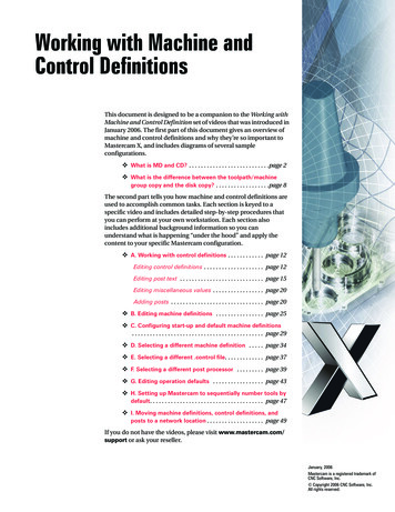
In the last two years the experiments performed on FTU, with a liquid lithium limiter, havegot extremely positive results. The Capillary Porous System (CPS), proposed by the Russiancolleagues, has demonstrated its capability to counteract the JXB force on the liquid lithiumso that no droplets or strong influx of lithium were observed when the limiter was insertedin the SOL between 1 and 3 cm from the LCMS. New plasma regimes characterized bystrong peaked electron density profiles were spontaneously obtained when the electrondensity raises over 1.1020 m-3. In all the plasma current (.5-.7 MA) and electron densityranges (0.15-3.01020m-3) explored up to now on FTU, the plasma is extremely clean (Zeff 1.5) and the only impurity detected by the VUV survey instruments is lithium also indischarges with additional heating up to 1.2 MW. Furthermore the liquid lithium limiter haswithstand heat loads up to 5 MW/m3 for hundred milliseconds. [1,2]Also if the experiments and the theoretical explanations are ongoing, it is well assessed thatplasma performance are consequence of a reduce recycling due to the pumping capability ofthe lithium and the low Z of lithium (Z 3) and, on the other hand, it is mandatory to goahead in experiments to establish if a liquid surface could be used as plasma facingcomponent.The technological aspects for utilizing a metallic liquid divertor on FAST and/or the firstwall of DEMO require new developments. First step is to built for FTU, a limiter able toact as main limiter and to demonstrate its capability to be cooled and refuelled during theplasma discharge. The proposal is to insert into FTU a wide panel ( 60º in toroidaldirection) in the bottom of the machine as illustrated in Fig. 1.1.This proposal will be developed in two steps. In the first, the single base element of thepanel will be tested on FTU. This element will be inserted on FTU utilizing the samemechanical structure built for the actual liquid lithium limiter but with the cooling andlithium refilling system tailored also for the second step. This first step is crucial for apositive assessment of the Capillary Porous System as possible plasma facing candidate forfuture devices. It will be very important, also in a single element system, to demonstrate thatthe cooling and the refuelling systems fit the requirements keeping the temperature in theright range and avoiding damages to the CPS structure by continuous lithium refuelling.However the single element limiter can’t act as main limiter, that will be possible only withthe panel limiter, many single elements put together, that will be mounted on FTU if thetests on the single element will be positive. The main goal of the panel will be the proof ofprinciple that a liquid metallic limiter is able to act as main limiter, i.e. the liquid lithiumsurface geometrically defines the last closed plasma magnetic surface.In fig. 1.2 the new liquid lithium limiter is shown and in table 1.2 the main parameters aresummarized.The project for the single base element has been completed in this year and the next yearshould be implanted on FTU.ParameterValueInitial lithium surface temperature 200ºCLithium surface temperatureduring plasma interaction 450-550ºCPower of heat removalup to 100 kW
Plasma interacting area 100 cm2Lithium amount (volume/weight)up to 70 cm3 / 35 gElement dimensions (L H W)330 205 32 mmTable 1.2 - Main parameters of the new liquid lithium limiter
Fig 1.1 - Top view and cross section of the panel liquid limiter for FTU13452Fig. 1.2 - The new liquid lithium limiter; 1 Mo Singlestructural element - 2 Inlet and outlet liquid cooling systemtubes - 3 CPS (Capillary Porous System) 4- Li reservoir 5- Lifilling tube.
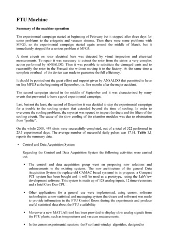
Fig. 1.3 - Source of downtime in 2008. Machine is the greatest cause of delay with 44,5% of thetotal.[1][2]M.L. Apicella et. al. J. Nucl. Materials 363-365 (2007) 1346-1351MAZZITELLI, G., et al 2008 “Status and perspectives of the liquid material experiments in FTU andISTTOK“, Proc. 22nd Int. Conf. on Fusion Energy 2008 (Geneva, Switzerland, October 2008)(Vienna:IAEA) file EX-P4-6 /html/index.htm
repository projects management tools were delivered as well as a ticketing trouble system to support users help desk. A number of 100 users accessed to the Gateway at the end of 2008 beginning to make . withstand heat loads up to 5 MW/m3 for hundred milliseconds. [1,2]