Transcription
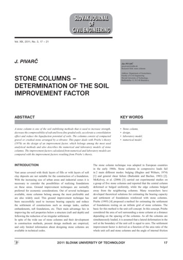
Vol. XIX, 2011, No. 3, 17 – 21J. PIVARČJán PIVARČjan.pivarc@stuba.skResearch field: stone columnsAddress: Department of Geotechnics,Faculty of Civil EngineeringSlovak University of Technology,Radlinského 11, 813 68 Bratislavastone columns –determination of the soilimprovement factorABSTRACTKEY WORDSA stone column is one of the soil stabilizing methods that is used to increase strength,decrease the compressibility of soft and loose fine graded soils, accelerate a consolidationeffect and reduce the liquefaction potential of soils. The columns consist of compactedgravel or crushed stone arranged by a vibrator. This paper deals with Priebe s theory(1976) on the design of an improvement factor, which belongs among the most usedanalytical methods and also describes the numerical and laboratory models of stonecolumns. The improvement factors calculated from numerical and laboratory models arecompared with the improvement factors resulting from Priebe s theory. IntroductionVast areas covered with thick layers of fills or with layers of softclay deposits are not suitable for the construction of a foundation.With the increasing size of urban areas and industrial zones it isnecessary to consider the possibilities of realizing foundationson these areas. Ground improvement techniques are normallypreferred for economic considerations. Out of several techniquesavailable, stone columns belong among the most preferable andare also widely used. This ground improvement technique hasbeen successfully used to increase bearing capacity and reducethe settlement of constructions such as storage tanks, earthenembankments, raft foundations, etc. Their main advantage lies inimproving the soil properties below a structure (raft and depth) andfollowing the reduction of an irregular settlement.In spite of the wide use of stone columns and their developmentin construction methods, present design methods are empirical,and only limited information about designing stone columns areavailable in technical codes.Stone column,design,laboratory model,numerical model.The stone column technique was adopted in European countriesin the early 1960s. Stone columns in compressive loads failin 2 main different modes: bulging (Hughes and Withers, 1974)[1] and general shear failure (Barksdale and Bachus, 1983) [2].McKelvey, et al. (2004) [3] carried out experimental studies ona group of five stone columns and reported that the central columndeformed or bulged uniformly, while the edge columns bulgedaway from the neighboring columns. Many researchers havedeveloped theoretical solutions for estimating the bearing capacityand settlement of foundations reinforced with stone columns.Priebe (1995) [4] proposed a method for estimating the settlementof foundations resting on an infinite grid of stone columns. Thebasic for this method is the unit cell concept. In this concept, Priebeconsidered the area of soil surrounding a stone column at a distancedepending on the spacing of the columns. As all the columns aresimultaneously loaded, it is assumed that a lateral deformation in thesoil at the boundary of the unit cell is equal to zero. The settlementimprovement factor is derived as a function of the area ratio of thewhole unit cell and stone columns and the angle of internal friction2011 SLOVAK UNIVERSITY OF TECHNOLOGY17
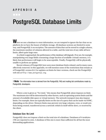
2011/3 PAGES 17 — 21Tab. 1 Properties of materials used in the experiments.Materialw (%)S5-SC16G2-GP0Edef (MPa)μ3.10.35450.2of the column material. With the exception of the area near the edgesof the loaded area, the behavior of the stone columns is the same;thus, only one column unit needs to be analyzed.This study is focused on a comparison of numerical, analytical andlaboratory model settlements to estimate the improvement factor ofsoil improved by stone columns. All the models in this study wereprepared by the vibro replacement method, which means that soil isremoved from a hole and not compacted to the sides such as in thevibro displacement method.cu (kPa)φ ( )1624045γd,max (kN/ m3)γ (kN/ m3)16.0114.9717.3616.52After the formation of the stone columns, the “load – settlement“behavior of the improved complex was observed. A rigid 10 mmthick steel plate was used as a loading plate. The loading wasapplied by a compactor with a constant velocity of 5 mm/min. Thus,the increased force and deformation were observed by electronicsensors at intervals of 1 sec. The left side of figure 3 shows the finalshape of the stone column when the whole complex of the stonecolumn and surrounding soil was loaded. On the right side the finalshape of the column is deformed by bulging when only that area oflaboratory modelThe laboratory experiments were carried out using stone columnswith diameters of about 60 mm and lenghts of 300 mm, 420 mmand 540 mm. All the laboratory experiments were performed withstone columns surrounded by clayey sand, S5–SC according toSTN 73 1001, in cylindrical test boxes with a height of 600 mmand with variable inner diameters from 125 mm to 253 mm. Thecylindical boxes represent the required area of a unit cell arounda stone column. A triangular pattern of stone columns was underconsideration. Testing of the stone columns was carried out with soilparametres acquired from laboratory tests of samples removed fromthe cylindrical test boxes after compaction of the soil. The stonecolumns were modeled as a floating unit in the soil space; that is, thebottom part of the longest column is about 1 d, or, about 60 mm fromthe bottom of the test box. Because the stone column has relativelyless stiffness in comparison to a conventional pile and also becausea horizontal deformation is more expected than a vertical one, thedistance of the stone column of about 60 mm from the bottom of thetest box is adequate. The ratios of the length of the stone columnsto the diameter of the stone columns l/d are modeled as 5, 7 and 9.The test was carried out in a test box filled with clayey sand S5–SCwith a total cohesion cu 16 kPa. The humidity of the soil in thebox was set before testing, so an appropriate quantity of clean waterwas poured into dry soil. Every experiment was realized with thesame humidity of soil of about 16%. All the samples were left forat least 24 hours for saturation before putting them into the boxesand compacting and forming the stone column (fig. 1, 2). The stonecolumns were formed from gravel, which was classified accordingthe STN 73 101 as G2 – GP. The fractions of the gravel were from2 mm to 5 mm. All the soil and gravel properties are seen in table 1.18Fig. 1 Compacting of soil prepared for the formation of the stonecolumns.Fig. 2 Installing a stone column into the soil and a compacted stonecolumn.Stone columns – determination of the soil improvement factor
2011/3 PAGES 17 — 21Tab. 3 Factor of improvement of soil.Fig. 3 Shape of the failed stone column after the area of SC wasloaded; the whole area of the SC and surrounding soil was loaded(equivalent area).s/dFactor of improvement - μ22.4331.6741.36the stone column was loaded. This subexperiment was carried outto verify the influence of the loading area on the deformation of thestone columns. The results are in good agreement with the results ofHughes and Withers [1].Table 2 summarizes the settlements of the SC after various pressureswere applied. Because the behavior of the soil under a loading platein the cylindrical test boxes is similar to that of an oedometer, theoedometric modulus of the improved soils for different spacing/diameter ratios was calculated. All the results, including the oedometrictest of the unimproved soil, are summarized in table 2. Table 3 showsthe final soil improvement factor with the stone columns calculatedlike the settlement ratio of the unimproved to improved soil.Numerical modelFig. 4 FE meshing and typical deformed mesh after SC loaded andequival area loaded.For the numerical modeling of the stone columns in cylindricaltest boxes, the Mohr Coulomb elastic prefect plastic criteria formodeling soil was chosen using PLAXIS V8 software. Fifteen nodeelements were applied. The finite element (FE) meshing is shown infigure 4. The boundary conditions along the vertical boundaries ofthe axially symmetrical model are fixed for the lateral deformations.The boundary condition allows vertical deformation. Fig. 4 alsoshows a typical deformed mesh after loading only the stone columnarea and a typical deformed mesh after loading the equivalent areaof the stone column.All the soil and gravel properties used in the numerical model aresummarized in table 1.Tab. 4 summarizes the settlements of the SC complex after variouspressures are applied, similarly to tab. 2. Table 5 shows the final soilimprovement factor with the stone columns.Tab. 2 Settlements of SC after various pressures and the oedometric modulus.Experiments/dDiameter of loadingplate (m)Settlement for50 kPa (m)Settlement for100 kPa (m)oedometricmodulus (MPa)Equivalent area loaded20.1150.00210.005828.06Equivalent area loaded30.1810.003140.009455.10Equivalent area loaded40.2430.004920.0124.24Oed. test– unimpr. soilStone columns – determination of the soil improvement factor3.119
2011/3 PAGES 17 — 21Tab. 4 Settlements of SC after different pressure and oedometric modulus.Experiments/dDiameter ofloading plate (m)Settlement for50 kPa (m)Settlement for100 kPa (m)Equivalent area loaded20.1250.003970.008027.96Equivalent area loaded30.1910.005620.011305.34Equivalent area loaded40.2530.006640.013644.29Equivalent area loaded with no SC40.2530.01500.02453.16Tab. 5 Soil improvement factor.oedometric modulus(MPa)Tab. 6 Soil improvement factor.s/dFactor of improvement - μs/dFactor of improvement - μ22.5222.7631.6931.6941.3641.39analytical design according TO priebeconclusionsThis approach includes one column and the contributory surroundingsoil (unit cell) - fig. 5.A comparison of all three approaches to estimate the soil improvementfactor by the stone columns with Priebe s original diagram is shownin fig. 6. The agreement of the results of the improvement factorcalculated by Priebe s method and, the FE method and obtainedfrom the laboratory experiments appears satisfactory. All the modelsin this study were prepared by the vibro replacement method, whichmeans that soil was removed out from the hole and not compactedto the sides such as in the vibro displacement method.Acknowledgement:This paper is part of the VEGA 1/0619/09 research programFig. 5 Unit cell (Barksdale,R.D.- Bachus,R.C. 1983) [2].Priebe assumes that this unit is surrounded by a rigid frictionlesswall and that the vertical deformations are equal in every plane.He assumes that the column is stiff and uncompressible, whereasthe surrounding soil is elastic. The stress distribution in the soil isisotropic, and a rigid base plate is above the stone column. Also, theload transferred to the subsurface soil is uniform.For the analytical calculations the same soil properties as in thenumerical and laboratory models were used. Table 6 shows the finalsoil improvement factor with the stone columns.20Fig. 6 Comparison of the improvement factors calculated by thedifferent approaches.Stone columns – determination of the soil improvement factor
2011/3 PAGES 17 — 21REFERENCES[1] Hughes, J.M., Withers, N.J.: Reinforcing of soft cohesive soilswith stone columns, 1974.[2] Barksdale,R.D., Bachus,R.C.: Design and construction of stonecolumns, 1983.[3] Mckelvey, D., Sivakumar, V., Bell, A., Graham, J.: Modellingvibrated stone columns in soft clay, 2004.[4] Priebeh, J.: The Design of Vibro Replacement, 1995.Stone columns – determination of the soil improvement factor21
Priebe (1995) [4] proposed a method for estimating the settlement of foundations resting on an infinite grid of stone columns. The basic for this method is the unit cell concept. In this concept, Priebe considered the area of soil surrounding a stone column at a distance depending on the spacing of the columns. As all the columns are