Transcription
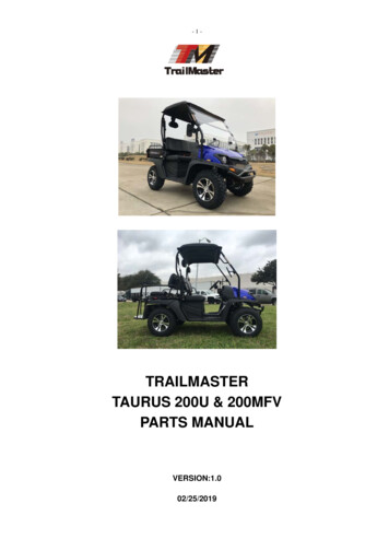
TrailMaster MINI XRSSet up instructionVersion: 2.02011/11/28This set up instruction guides our customer to set up the go kart TrailMaster MINI XRS stepby step to ensure a correct assembly for safe driving.
MINI XRSSet up instruction1. Check the components after opening the box.1.1 One sport steering wheel (pic.1)Pic.11.2.1 one standard parts package, one manual, one flag, four hub coves,plastic fixing bolt and nut for flag, 5 cable bundles and one steering boltcover.1.2.2 In the standard parts package: 14 bolts M8x45, 2 cotter pins 3X40,2 cotter pins 2.5X25, 2 castle nuts, 20 R-washers, 6 self-locking nuts M8,4 M8x35 bolts, 1 M6x30 bolt, 1 M6x12 bolt, 1 M6x16 bolt and 2self-locking nuts M6 (pic.2)Pic.22
MINI XRSSet up instruction1.3 Two bar cages (pic. 3)Pic.31.4 One top cross bar (Pic.4)Pic.41.5 Two side bars for left and right side with tube seats (Pic. 5)Pic.53
MINI XRSSet up instruction1.6 One top cross bar with tube seats (Pic.6)Pic.61.7 front wheels left and right; rear wheels left and right (pic.7)Pic.71.8 1 stand exhaust guard and bracket (Pic.8)Pic.84
MINI XRSSet up instruction2. Assembly2.1 Assemble the rear shocks (pic.9): take down the bolts from the shocks,lift the rear swing arm to let the top of shock into the fixing seats of frame,use 22-29NM torque to fix the shocks attached the frame. (Note: 1NM 0.74 lb ft)Pic.92.2 Assemble the rear wheels (pic.10): Take off the nut M14x1.5 and Φ14 washer from the rear axle. Raise up the tail part and set up the rearwheel onto the rear axle, screw the washer and nut screw tightly with83-98NM, then open the cotter pin 3X40 for fixing, cover the hub cover.Pic.102.3 Assemble front lower suspension arm (Pic.11): lift the front part of go5
MINI XRSSet up instructionkart onto a table. Take down the nut and washer from the spindle and strutsupport, insert the ball head into the mount position of lower suspensionarm (square part of ball head is placed to the square hole of suspensionarm), put on the washer and nut. Screw on the bolt with torque 37-44NM.At last open the cotter pin 2X20 for fixing.Pic.112.4 Assemble the front wheel (pic.12): Take off the nut M12x1.25 and Φ12 washer from the rear axle. Raise up the front part and set up the rearwheel onto the rear axle, screw the washer and nut screw tightly with55-62NM, cover the hub cover.Pic.126
MINI XRSSet up instruction2.5 Assemble the long bar cages (Pic.13): put two sides of long bar cagesonto the connection rods on frame fixing with bolt M8x45, R-washer andM8 nut. Tighten the bolts.Pic.132.6 Assemble the side bar (pic.14): Put one side of side bar attaching thelong bar cage, connect the side bar and the long bar cage together withbolt M8x45, R-washer, screw the bolts 3 turns. Connect another side ofside bar onto the connection rod of frame with R-washer, bolt M8x45 andbolt. Screw on all the bolts tightly.Pic.147
MINI XRSSet up instruction2.7 Assemble the cross bar (Pic.15): Connect the cross bar with two longbar cages with bolt M8X50 and R-washer, do not tightening the bolts atthis step.Pic.152.8 Assemble the roof rack bars (pic.16): fix the rear cross bar with longbar cage together using bolt M8x50 and R-washer.Pic.162.9 Screw on the bolts from step 2.5 to 2.8 with torque 22-29NM.2.10 Assemble the yellow flag and flagpole: use the plastic bolt and nut tofix the flagpole on the rear cargo rack.2.11 Assemble the steering wheel: Check the front wheel is at the straightposition. Take down the bolts on steering shaft, put the steering wheelcorrectly onto the steering shaft (as shown in pic.17). Screw the bolts8
MINI XRSSet up instructionwith 11-16NM torque. Cover the steering bolt cover.Pic.172.12 Assemble the stand exhaust guard and bracket (Pic.18): place thestand exhaust guard on the mounting place of engine, insert the M6x12bolt from back to front and screw with a M6 self-locking nut. Fix the leftside of stand exhaust guard with M6x12 bolt as shown in Pic.18, fix thebracket on the cylinder head of engine. Screw tightly all the parts withM6x16 bolts and M6 self-locking nuts.Pic.189
MINI XRSSet up instruction3. Chain AdjustmentIn order to package the go-kart better, the chain adjustor isloosen by packaging for shipment. The customer should adjustthe chain before driving. In this instruction the process of chainadjustment is detailed introduced:A. For the new purchased go-kart, the customer should onlytighten the nut of chain adjustor to adjust the rear chain. Theinitial adjustment of chain has been carried out before delivery.The tension of chain adjustment is required between 15-20mm.B. If after step. 1 tightening the nut of chain adjustor thechain is still too loose or too tight, another nut at the underpartof chain adjustor must be adjusted accordingly.10
MINI XRSSet up instructionC. After the go-kart has been driven for a while, the drivechain on clutch will be loosen and should be readjusted. At first,four bolts fixing the engine on mount plate have to be loosenuntil the engine can be moved. Then, adjust the chain adjustingbolt at the front side of engine to tighten the chain to anappropriate tension. At last, after adjusting screw the four boltstightly.11
MINI XRSSet up instructionBefore driving please read the user manual of TrailMaster Go-kart MINIXRS carefully, you will be given with important safety information andadvices.Thanks a lot for choosing TrailMaster Go-kart MINI XRS.For more products of TrailMaster, please visit www.bvpowersports.com !BV Powersports, LLC12
This set up instruction guides our customer to set up the go kart TrailMaster MINI XRS step by step to ensure a correct assembly for safe driving. MINI XRS Set up instruction . 2 1. Check the components after opening the box. 1.1 One sport steering wheel (pic.1) Pic.1 . 1.2.1 one standard parts package, one manual, one flag, four hub coves, .