Transcription
Module II – CircuitAnalysisCircuit Analysis BasicsJoint EPRI/NRC-RES Fire PRA WorkshopJune 25-29, 2018Gabe Taylor – U.S. NRCDaniel Funk – JENSEN HUGHESDane Lovelace – JENSEN HUGHESA Collaboration of the Electric Power Research Institute (EPRI) & U.S. NRC Office of Nuclear Regulatory Research (RES)
CIRCUIT ANALYSIS BASICSObjectives Provide the minimum level of information needed tounderstand the functionality of common circuits analyzed inthe remainder of the course Focus on three common circuits– Air operated valve / Solenoid operated pilot valve (AOV / SOV)– Motor operated valve (MOV)– Circuit Breaker (PCB – MVPCB & LVPCB) Present overviews of typical nuclear power plant electricalpower distribution system2
CIRCUIT ANALYSIS BASICSCircuit Design Basics Concepts– Typical circuit devices and symbols– ANSI/IEEE standard device numbers– Types of drawings and their purpose– Equipment of Interest– Operation of common equipment3
CIRCUIT ANALYSIS BASICSTypical Circuit Devices Circuit breakers and fusesMotor starters and contactorsRelays and contactsTerminal blocksControl power transformers (CPTs)Actuating coilsIndicating lamps and alarmsSwitches–––––4Control/hand (maintained, momentary, spring-return to normal)Limit and torqueSensorsTransfer and isolationPosition
CIRCUIT ANALYSIS BASICSTypical Device Symbols – Refer to Handout5
CIRCUIT ANALYSIS BASICSIEEE Standard Devices Numbers – Refer to Handout6
CIRCUIT ANALYSIS BASICSTypes of Drawings and Their Purpose Single-line drawingsThree-line drawingsCircuit AnalysisElementary or schematic diagramsCable RoutingBlock diagramsCable raceway schedulesWiring or connection drawingsInstrument loop diagramsVendor shop drawingsEquipment arrangement or location drawingsTray and conduit layout drawingsUnderground and duct-bank layout drawingsSpecialty drawings (electrical penetration, logic, load lists,coordination diagrams, short circuit calculations) Piping and instrument diagrams7
CIRCUIT ANALYSIS BASICSDrawing Types – Refer to Electrical Basic Drawing Index8
CIRCUIT ANALYSIS BASICSEquipment of Interest Cables and panel wiring Raceways Valves Transformers – big to small High, medium, and low voltage switchgear Protective relays Circuit breakers Instrumentation9
CIRCUIT ANALYSIS BASICSEquipment of Interest – Cables & Raceways Cables and Panel Wiring– Single-conductor cable– Conduit– Multi-conductor cable– Tray – ladder and solid– Triplex cable– Size conventions andampacity– Shielded, unshielded, &armored– Materials – conductor,insulation, & jacket10 Raceway Types– Wireways– Pull boxes– Junction boxes– Terminal boxes– Duct-banks– Embedded conduit– Air drops
CIRCUIT ANALYSIS BASICSEquipment of Interest – Valves Air Operated Valves (AOV)– Pilot solenoid operated– Bi-modal function– Modulate function Solenoid Valves (SOV)– AC & DC operated Motor Operated Valve (MOV)– Typical design– Inverted design11
CIRCUIT ANALYSIS BASICSEquipment of Interest – Transformers Power Transformers––––Main transformersUnit auxiliary transformers (UAT)Startup or reserve auxiliary transformer (SUT, RAT)Station service transformer (SST) Control Power Transformers (CPT) Instrument Transformers– Potential transformer (PT)– Current transformer (CT)– Zero sequence current transformer Specialty Transformers12
CIRCUIT ANALYSIS BASICSEquipment of Interest – Switchgear & Relays Switchgear– Medium Voltage 1,000 V – 15,000 V 13.8 kV, 12.47 kV, 7.2 kV, 6.9 kV, 4.16 kV, 2.4 kV– Low Voltage Up to 1,000 V 120 V, 208 V, 240 V, 277 V, 480 V, 600 V– Typically metal-clad, indoor, draw-out design– Separate control power circuit and protective devices Protective Relays– Overcurrent relays (50, 51, 50N, 51N, 50G)– Differential relays (87, 87T, 87B)– Undervoltage relays (27)– Frequency relays (81)– Reverse power relays (32, 67)– Lockout relays (86)13
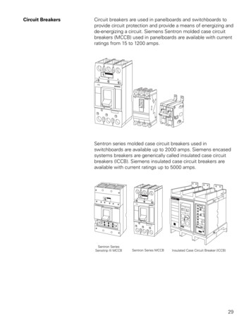
CIRCUIT ANALYSIS BASICSEquipment of Interest – Circuit Breakers Medium Voltage Power Circuit Breakers– Power Circuit Breakers (PCB) Vacuum Circuit Breakers (VCB) Air Circuit Breakers (ACB) Gas Circuit Breaker (GCB)– 1,000 V – 15 kV Low Voltage Power Circuit Breakers (LVPCB)– Below 1,000 V– Same basic features as medium voltage powerbreakers– Internal or external trip devices Molded Case Circuit Breakers– Internal trip devices Thermal and/or magnetic– Generally manually operated14
CIRCUIT ANALYSIS BASICSEquipment of Interest – Motors AC, DC, 1-phase, 3-phase Synchronous vs. induction design Large motors controlled by circuit breaker Smaller motors often controlled by a “motor starter” Continuous duty (pump) vs. intermittentduty (MOV) MOVs and DC motors are most oftenreversing design High temp is usually an alarm or time-delay trip Locked rotor current must be considered15
CIRCUIT ANALYSIS BASICSEquipment of Interest – Process Inst & Rx Protection Process ssure Reactor Trip– Trip signals– Actuation circuitry Engineered Safety FeaturesActuation System– Input signals– Actuation logic– Solid-state protection system (SSPS) Digital Control Systems (DCS)16
CIRCUIT ANALYSIS BASICSElectrical Circuit Operation – Common Circuits Air Operated Valve (AOV)– Main air valve– Pilot solenoid valve Direct acting solenoid valve Motor Operated Valve (MOV) Power Circuit Breakers (PCB)– Medium Voltage Power Circuit Breaker– Low Voltage Power Circuit Breaker17
Solenoid Operated Valve (SOV) An SOV is an electromechanically operated device– Valve is controlled by electric current– Commonly used to control air operated valves(AOVs)– When used for AOV, called a pilot valve18
Air Operated Valve (AOV)19
Air Operated Valve (AOV)20
Air Operated Valve (AOV)21
Where is the AOV in this picture?22
Direct Acting SOV23
SOV Elementary Diagram24
SOV Block Diagram25
Lets Walk ThroughSOV Operation26
Motor Operated Valve A Motor Operated Valve (MOV) is a valve with an actuatordriven by an electric motor MOVs typically serve an “On-Off” or “Open-Close” purpose MOVs are not typically used for throttling Valve types can include– Gate– Ball– Butterfly27
MOV Actuator28
MOV Actuator29
MOV Elementary Diagram30
Lets Walk ThroughMOV Operation31
Power Circuit Breakers Medium Voltage Power Circuit Breakers– Power Circuit Breakers (PCB) Main contacts Arc chutes Connection stabs Operating coils and springs– Separate 125 VDC control power– Separate close and trip coils– Fails “as-is” on loss of control power– No overcurrent protection w/o control power– Separate trip devices – protective relays32
PCB Elementary Diagram33
Lets Walk ThroughPCB Operation34
CIRCUIT ANALYSIS BASICSAny Questions?35
CIRCUIT ANALYSIS BASICS. Typical Circuit Devices Circuit breakers and fuses Motor starters and contactors Relays and contacts Terminal blocks Control power transformers (CPTs) Actuating coils Indicating lamps and alarms Switches - Control/hand (maintained, momentary, springreturn to normal)-- Limit and torque - Sensors