Transcription
3.7inch e-PaperVersion: Tentative 0.2TECHNICAL SPECIFICATIONMODEL NO: 3.7inch e-PaperThe content of this information is subject to be changed withoutnotice. Please contact Waveshare for further information. Customer’s ConfirmationCustomerDateByPAGE 1
3.7inch e-PaperRevision HistoryRev.Issued DateRevised ContentsTentative 0.120190516NewTentative 0.220190517Add 7-2Add 9-3PAGE 2
3.7inch over1-Revision history2-Contents31General description42Features43Mechanical specifications44Mechanical drawing of EPD module55Input/Output terminals66Electrical characteristics77Power sequence138Optical characteristics169SPI command description1710SPI control registers2011Reference circuit7412Handling, safety and environment requirements7513Reliability test7614Border definition and scan direction7715Packing78PAGE 3
3.7inch e-Paper1. General descriptionThis display is a reflective electrophoretic E Ink technology display module based on glassactive matrix TFT substrate. It has 3.69” active area with 280(H) x 480(V) pixels, the display iscapable to display images at 2 gray levels (1 bit) depending on the display controller and the associatedwaveform file it used.2. FeaturesHigh contrast reflective/electrophoretic technology280(H) x 480(V) displayHigh reflectanceUltra wide viewing angleUltra low power consumptionPure reflective modeBi-stableCommercial temperature rangePortrait pin out. Landscape mode scan.Glass substrate.All in one IC that integrated source driver, gate driver, TCON, PMIC and OTP memory in themodule.Built in temperature sensor: On-Chip: -25 50 2.0 / 8-bit status3. Mechanical specificationsParameterScreen SizeDisplay ResolutionActive AreaPixel PitchPixel ConfigurationOutline DimensionSpecifications3.69280(H) x 480(V)47.32(H) x 81.12(V)0.169(H) x 0.169(V)Square54.9(H) x 47.32(V) 0.78 (D)UnitInchPixelmmmmModule WeightTBDgNumber of Gray2 Gray Level (monochrome)Display operating modeReflective modeSurface treatmentNonPAGE 4mmRemark150dpi
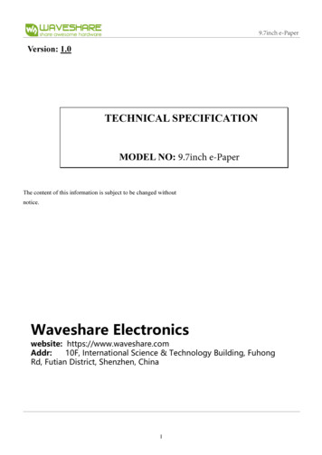
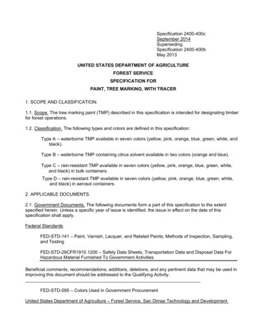
3.7inch e-Paper4. Mechanical drawing of EPD modulePAGE 5
3.7inch e-Paper5.Input/ouput terminals5-1)Pin out listFPC connector: Panasonic Y5B AYF532435 or P-TWO 196225-24041 or spec compatible connectors.Pin NoSignalDescription1VSSGround2GDRN-MOS gate control3RESECurrent sense input for control loop.4NCNC5VSHRPositive source voltage for reserve6TSCLI2C clock for external temperature sensor7TSDAI2C data for external temperature sensor8BS1Input interface setting9BUSYDriver status.10RES#Global reset pin11D/C#Serial communication Command/Data input12CS#Serial communication chip select.13SCLSerial communication clock input.14SDASerial communication data input.15VCIDigital/IO/Analog power3.3V16VCIDigital/IO/Analog power3.3V17VSSGround18VDD181.8V voltage input &output1.8V19VOTPOTP program power7.5V20VSHPositive source voltage 5V21VGHPositive gate voltage 10V22VSLNegative source voltage-5V23VGLNegative gate voltage-10V24VCOMVCOM output-1.0V -4.0VPAGE 6Notes5V (Reserve.)
3.7inch e-Paper6.Electrical characteristics6-1) Absolute maximum ratingParameterDigital/IO/Analog powerOperating Temp. RangeStorage TemperatureSymbolVCITOTRTSTGRating-0.3 to 5.50 to 50-25 to 70UnitV 6-2) Panel DC nitSignal groundVSS-0-VDigital/IO/analogVCI2.43.33.6Vvoltage supplyIVCI---mAP---mWPSTBY---mW0-40 -25-60 Power panelStandby power panelVCI 3.3VOperating temperatureStorage temperature-The maximum average Currents for power consumption and Max. Currents are measureserve using86Hz waveform with following pattern transition: from black and white single checker pixel pattern toinversed black and white single checker pixel pattern. (Note 6-1)-The Typical power consumption is measureserve using 86Hz waveform with following patterntransition: from horizontal 2 gray scale pattern to vertical 2 gray scale pattern. (Note 6-2)-The standby power is the consumed power when the panel controller is in standby mode.-The listed electrical/optical characteristics are only guaranteed under the controller & waveformprovided by Waveshare.-Vcom is recommended to be set in the range of assigned value 0.1 VNote 6-1Image flow to measure maximum power consumption.TBDNote 6-2Image flow to measure typical power consumption.TBDPAGE 7
3.7inch e-Paper6-3 )Panel AC characteristicsVCI 3.0V to 3.6V, unless otherwise SERIAL COMMUNICATIONCSBSCLSDA(DIN)(DOUT)D/CTCSS100nsChip select setup timeTCSH100nsChip select hold timeTSCC50nsChip select CSB setup timeTCHW500nsChip select setup timeTSCYCW100nsSerial clock cycle (Write)TSHW35-nsSCL “H” pulse width (Write)TSLW35-nsSCL “L” pulse width (Write)TSCYCR200-nsSerial clock cycle (Read)TSHR85nsSCL “H” pulse width (Read)TSLR85nsSCL “L” pulse width (Read)TSDS30nsData setup timeTSDH30nsData hold timeTACC10nsAccess timeTOH15nsOutput disable timeTDCS20nsDC setup timeTDCH20nsDC hold timeDriverSource driver rise timetrS5usSource driver fall timetFS5usGate driver rise timeTrG5usGate driver fall timetFG5usVCOM rise timetrCOM1msVCOM fall timetFCOM1msPAGE 899% final value99% final value99% final value
3.7inch e-PaperPAGE 9
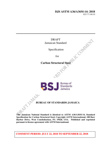
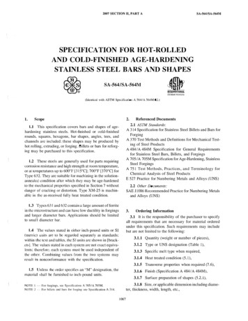
3.7inch WTSHWTDCSTDCHD/CTSDS TSDHSDA( DIN)VIHD6D7VIL4CSBD5D0pin serial interface characteristics (write TDCHD/CTACCTACCSDA(DOUT)TOHD6D74D5pin serial interface characteristics (read mode)Figure 1: SPI interface timingPAGE 10D0TCHW
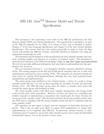
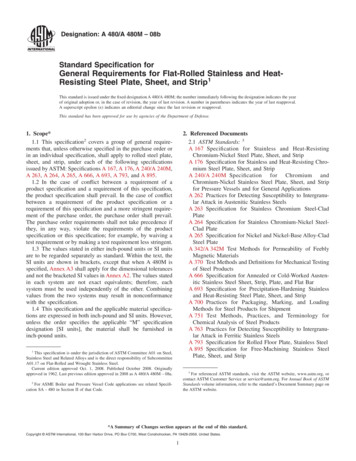
3.7inch e-Paper6-4 )Refresh rateThe module is applied at a maximum refresh rate of 50 Hz.Min-Refresh RateMax50 Hz6-5 ) Data transmission waveformExample1: LUT all states (7 states) complete or phase number 0, the driver will send 2 frame VCOM and datato 0 V.InternalVsyncSPI(input)2 frameTSC off(41h)LUTC(20h)LUT Data Data start(21 24h) transmission(10h and 13h)Data stop(11h)I2C(for EEPROM)Driver(action internal)BUSY NVCOMDATADisplaytransmission okDisplaytransmissionLUT1Frame 1-N VCOMFrame 1-N DATALUT 2Frame 1-N VCOMFrame 1-N DATAFigure 2: Data transmission example1 waveformPAGE 11Vcom DCFloating0VFloating
3.7inch e-PaperExample2: While level selection in LUT is “11”, the driver will float VCOM and data.Figure 3: Data transmission example 2 waveformPAGE 12
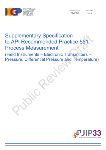
3.7inch e-Paper7. Power sequence7-1)Power on/off sequenceIn order to prevent IC fail in power on resetting, the power sequence must be followed as below.Figure 4: Power on sequencePAGE 13
3.7inch e-PaperFigure 5: Power off sequenceFigure 6: DSLP sequencePAGE 14
3.7inch e-Paper7-2)RST NFigure 7: RST N sequencePAGE 15
3.7inch e-Paper8. Optical characteristics8-1)SpecificationsMeasurements are made with that the illumination is under an angle of 45 degrees, the detection isperpendicular unless otherwise ectanceWhite2530-CRContrast Ratio-57-T 25oCUNITNote%Note 9-1-WS: White state , DS: Dark stateNote 9-1: Spectrum meter: Eye – One Pro Spectrophotometer8-2)Definition of contrast ratioThe contrast ratio (CR) is the ratio between the reflectance in a full white area (Rl) and the reflectance in a darkarea (Rd): CR Rl/RdEye–One Spectrophotometer45 45 8-3)Reflection ratioThe reflection ratio is expressed as:R Reflectance Factorwhite board x( Lcenter / Lwhite board )Lcenter is the luminance measureserve at center in a white area (R G B 1). Lwhite board is the luminance of astandard white board. Both are measureserve with equivalent illumination source. The viewing angle shall beno more than 2 degrees.PAGE 16
3.7inch e-Paper9. SPI command description9-1) Three-wire serial port interfaceThis display use the 3-wire serial port as communication interface for all the function and command setting. 3Wire communication can be bi-directional controlled by the “R/W” bit in address field. The 3-Wire engineact as a “slave mode” for all the time, and will not issue any command to the 3-Wire bus itself.Under read mode, 3-Wire engine will return the data during “Data phase”. The returned data should be latchedat the rising edge of SCL by external controller. Data in the “Hi-Z phase” will be ignoreserve by 3-Wire engineduring write operation, and should be ignoreserve during read operation also. During read operation, externalcontroller should float SDA pin under “Hi-Z phase” and “Data SCCTSLWTSDS TSDHSDA(DIN)VIHVILD/CXD6D7D03 pin serial interface characteristics (write SLRTSDS TSDHSDA(DIN)SDA(DOUT)VIHVILTOHTACCVIHVILD7D6D03 pin serial interface characteristics (read mode)PAGE 17
3.7inch e-Paper9-2) Four-wire serial port interfaceCSBVIHVILTcssTSCY CWTSLWVIHVILSCLTCSHTSCCTCH WTSH WTD CHTDCSD/CTSDS TSDHSDA( DIN)VIHD6D7VIL4CSBD5D0pin serial interface characteristics (write mode)VIHVILTcssTSCY CWTSLWVIHVILSCLTCSHTSCCTSH WTDCSTDCHD/CTACCTA CCSDA(DOUT)TO HD6D74D5pin serial interface characteristics (read mode)PAGE 18D0TCH W
3.7inch e-Paper9-3) Display flowPAGE 19
3.7inch e-Paper10. SPI control registers10-1) Register tableFollowing table list all the SPI control registers and bit name definition for display. Refer to the nextsection for detail register function D4D3D2D1D0W000000000W1RES[1]RES[0]REG ENBWRUDSHLSHD NRST NW000000001W1------W1--W1VSH [5]W1VSL [5]W1Panel setting (PSR)Power setting (PWR)VSHRCode-00H8Fh01HVDS EN VDG EN03hVCOM VGHL L VGHL L VGHL LHVV [2]V [1]V [0]00hVSH [4]VSH [3]VSH [2]VSH [1]VSH [0]3FhVSL [4]VSL [3]VSL [2]VSL [1]VSL [0]3FhVSHR [5] VSHR [4] VSHR [3] VSHR [2] VSHR [1] VSHR [0]0Fh[6]R02HPower OFF(POF)W000000010W000000011W1--02H03HPower off SequenceR03HT VDS O T VDSSetting(PFS)R04HPower ON 00110Power ON 000100001########00001000100H11H1Data flag---------Deep Sleep(DSLP)Data StartWR10Htransmission1 (DTM1)R11H06HBooster Soft StartR06HR07HBT PHA BT PHABT PHA BT PHA BT PHA BT PHA BT PHABT PHA57643210BT PHB BT PHBBT PHB BT PHB BT PHB BT PHB BT PHBBT PHB57643210BT PHC BT PHC BT PHC BT PHC BT PHCBT PHC543210Data Stop (DSP)WWRPAGE 2017h17h17h07HA5h10H
3.7inch e-PaperR12HDisplay Refresh (DRF)Data Start 2H13H2(DTM2)WPartial Data ####00hPartial DisplayW00001011016HRefresh(PDRF)W1########00hLUT for VCOMW00010000020H(LUT1)W1########00hWhite to White LUTW00010000121H(LUTWW)W1########00hBlack to White LUTW00010001022H(LUTBW/LUTR)W1########00hWhite to Black LUTW00010001123H(LUTWB/LUTW)W1########00hBlack to Black 125HW1W1W1W1Set M1)Partial Data StartR15Htransmission 2(PDTM2)R16HR20HR21HR22HR23HR24HR25HLUTC optionXON [9:8]XON [7:0]00hST CHV [9:8]ST CHV [7:0]10000h00h00h11026HR26HR30Hvcom stg sel[1:0]1OSC control (OSC)W1-W00R1100M[2:0]100b2w stg sel[1:0]00N[2:0]00000h30H3Ah040HTemperature SensorR40HCommand (TSC)D10/TS[7D9/TS[6] D8/TS[5] D7/TS[4] D6/TS[3] D5/TS[2] D4/TS[1] D3/TS[0]]PAGE 21--
3.7inch e-PaperR1Temperature SensorWCalibration D1D00010W1TSE-W001--R41HTemperature SensorR42HWrite (TSW)Temperature SensorW1W1W1W0WATTR[ WATTR[ WATTR[5 WATTR[ WATTR[ WATTR[2 WATTR[ WATTR[07]6]]4]3]]1]]WMSB[4 WMSB[3WMSB[1 WMSB[0WMSB[7 WMSB[6WMSB[2]WMSB[5]]]]]]]WLSB[7] WLSB[6] WLSB[5] WLSB[4] WLSB[3] WLSB[2] WLSB[1] WLSB[0]0100001RMSB[1]100h00h00h43HR1RMSB[7] RMSB[6] RMSB[5] RMSB[4] RMSB[3] RMSB[2]R1RLSB[7] RLSB[6] RLSB[5]VCOM and DATAW00101000050Hinterval setting DI[0]D7hLower Power [0]22h001100001-----VRES(8)R43HRead (TSR)RLSB[4] RLSB[3]RMSB[0]42HRLSB[2] RLSB[1] RLSB[0]-R50HR51HR60HTCON setting (TCON)WWResolutionWR61Hsetting(TRES)WWWSource & gate startWR62HsettingWWWR70HR71HREVISION (REV)HRES(7) HRES(6) HRES(5) HRES(4) HRES(3)---011S start(7)S start(6)01W00001S start (5)S start(4)S start(3)--gscanG start(7)G startG startG start (6)(6)(4)G start[8]G 1]REV[0]REV[15] REV[14] REV[13] REV[12] REV[11]0112-0101--W0100R1--VV[5]WG startG startG start (2)(3)(1)0REV[7]1W-111-VRES(7) VRES(6) VRES(5) VRES(4) VRES(3) VRES(2) VRES(1) VRES(0)0RR80HR81H11R(AMV)1RStatus register(FLG)Auto Measure Vcom1PTL flag I C ERR010I2CData flagBUSYN0REV10] REV[09] REV[08]001PONPOFBUSY 0000181HVV[4]VV[3]VV[2]VV[1]VV[0]-AMVT[1] AMVT[0]80 H10hVcom Value (VV)PAGE 22
3.7inch e-PaperW010W1--00001082HVCDS [0]1FhVcom DC SettingR82HVCDSregister(VDCS)VCDS[5] VCDS [4] VCDS [3] VCDS [2][1]RA0HRA1HW010100000A0HW110100101A5hActive program(APG)W010100001A1HRead OTP DataW010100010A2HR1########-W011100101Program Mode (PGM)RA2H(ROTP)RE5HRE6HRE7HRE8HRE9HForce TemperatureLVD voltage SelectPanel Break CheckPower savingAUTO sequenceOTP LUT backup1REBHTS SET[ TS SET[ TS SET[5 TS SET[ TS SET[ TS SET[2 TS SET[ TS ----PSTAW01110001VCOM VCOMW[3]W[2]VCOMW[1]010LVD SE LVD SELL[1][0]VCOMSD W[3] SD W[2] SD W[1] SD W0111E5H00hE6H11hE7H-E8H00hE9H00hEBHprogramRead OTP LUTRECHbackup1RESERVEHOTP LUT backup2programRead OTP LUTREEHECH-EDH--EEHbackup2Checksum Program toREFHEFHOTPRF0HRF1HRemap LUT10000bkup lut2 enbkup lut1 enrmp2 table sel[3]rmp1 table sel[3]rmp2 table sel[2]rmp1 table sel[2]rmp2 table sel[1]rmp1 table sel[1]rmp2 table sel[0]rmp1 table sel[0]01W1---W1---W0111100W1------Set OTP programPAGE 23LUT banreg bankkF0H1Fh1FhF1H03h
3.7inch e-PaperRF2HRF3HRead checksumCalculate ChecksumW011110010R1########W011110011PAGE 24F2H00hF3H
3.7inch e-Paper10-2) Register description10.2.1 R00H (PSR): Panel setting ePSRW00000000000H1st ParameterW1RES[1]RES[0]REG ENBWRUDSHLSHD NRST N8FhNOTE: “-” Don’t care, can be set to VDD or GND levelDescription-The command defines as :BitName0RST NDescriptionRST N function1 : no effect. (default)0: Booster OFF, Register data are set to their default values, and SEG/BG/VCOM:floatingSHD N function1SHD N0 : Booster OFF, register data are kept, and SEG/BG/VCOM are kept floating.1 : Booster on. (default)SHL function2SHL0: Shift left; First data Sn Sn-1 S2 Last data S1.1: Shift right: First data S1 S2 Sn-1 Last data Sn. (default)UD function3UD0:Scan down; First line Gn Gn-1 G2 Last line G1.1:Scan up; First line G1 G2 Gn-1 Last line Gn. (default)Color selection setting4BWR0: Pixel with B/W/Reserve. Run both LU1 and LU2. (default)1: Pixel with B/W. Run LU1 onlyLUT selection setting5REG EN0 : Using LUT from OTP(default)1 : Using LUT from registerResolution setting00: Display resolution is 600x4487-6RES[1,0]01: Display resolution is 640x48010: Display resolution is 720x540PAGE 25
3.7inch e-Paper11: Display resolution is 800x600 (default)Notes:1. When SHD N become low, DCDC will turn off. Register and SRAM data will keep until VDD turn off. SD output and VCOM will baseon previous condition and keep floating.2. When RST N become low, driver will reset. All register will reset to default value. All of the driver’s functions will disable. SD outputand VCOM will base on previous condition and keep floating.10.2.2 R01H (PWR): Power setting W0000000011st ParameterW1------VDS ENVDG EN03h2nd ParameterW1----VCOM HVVGHL LV[2]VGHL LV[1]VGHL LV[0]00h3rd ParameterW1--VSH [5]VSH [4]VSH [3]VSH [2]VSH [1]VSH [0]3Fh4th ParameterW1--VSL [5]VSL [4]VSL [3]VSL [2]VSL [1]VSL [0]3Fh5th ParameterW1-VSHR [6]VSHR [5]VSHR [4]VSHR [3]VSHR [2]VSHR [1]VSHR [0]0FhNOTE: “-” Don’t care, can be set to VDD or GND levelDescription-The command defines as :1st Parameter:BitNameDescriptionGate power selection.0VDG EN0 : External VDNS power from VGH/VGL pins. (VDNG EN open)1 : Internal DCDC function for generate VGH/VGL. (default)Source power selection.1VDS EN0 : External source power from VSH/VSL pins.1 : Internal DC/DC function for generate VSH/VSL. (default)PAGE 26Code01h
3.7inch e-Paper2nd Parameter:BitNameDescriptionVGHL LV Voltage Level.000: VGH 20 v, VGL -20v (default)001: VGH 19 v, VGL -19v010: VGH 18 v, VGL -18v2-0VGHL LV011: VGH 17 v, VGL -17v100: VGH 16 v, VGL -16v101: VGH 15 v, VGL -15v110: VGH 14 v, VGL -14v111: VGH 13 v, VGL -13vVCOM Voltage Level0: VCOMH VSH VCOMDC,VCOML VSL VCOMDC(default)3VCOM HV1: VCOMH VGH, VCOML VGL3rd Parameter: Internal VSH power selection for B/W LUT. (Default value: 111111b)BitNameDescriptionInternal VSH power selection.000000: 2.4 v000001: 2.6 v000010: 2.8 v000011: 3.0 v .010111: 7.0V011000: 7.2 V5-0VSH011001: 7.4 V .111010: 14.0V111011: 14.2 V111100: 14.4V111101: 14.6V111110: 14.8V111111: 15.0VPAGE 27
3.7inch e-Paper4th Parameter: Internal VSL power selection for B/W LUT. (Default value: 111111b)BitNameDescriptionInternal VSL power selection.000000: -2.4 v000001: -2.6 v000010: -2.8 v000011: -3.0 v .010111: -7.0V011000: -7.2 V5-0VSL011001: -7.4 V .111010 :-14.0V111011: -14.2 V111100: -14.4 V111101: -14.6V111110: -14.8V111111: -15.0V5th Parameter: Internal VSHR power selection for Reserve LUT. (Default value: 00001111b)BitNameDescriptionInternal VSL power selection.0000000: 2.4 v0000001: 2.5 v0000010: 2.6 v0000011: 2.7 v .6-0VSHR0101110: 7.0 V0101111: 7.1 V0110000: 7.2 V .1010001: 10.5V1010010: 10.6 V1010011: 10.7 VPAGE 28
3.7inch e-Paper1010100: 10.8V1010101: 10.9V1010110: 11.0VNote:1.VSH VSHRRestriction10.2.3 R02H (POF): Power OFF POFW00000001002HNOTE: “-” Don’t care, can be set to VDD or GND levelDescription-The command defines as :After power off command, driver will power off base on power off sequence.After power off command, BUSY N signal will drop from high to low. When finish the power off sequence, BUSY Nsingal will rise from low to high.Power off command will turn off charge pump, T-con, source driver, gate driver, VCOM, temperature sensor, butregister and SRAM data will keep until VDD off.SD output and VCOM will keep floating.Restriction10.2.4 R03H (PFS): Power off Sequence Setting ePFSW00000001103H1st ParameterW1--Vsh off[1]Vsh off [0]Vsl off[1]vsl off[0]vshr off[1]vshr off[0]00hNOTE: “-” Don’t care, can be set to VDD or GND levelPAGE 29
3.7inch e-PaperDescription-The command defines as :1st Parameter:BitNameDescription00: 5ms. (default)01: 10ms1-0vshr off10: 20ms11: 40ms00: 5ms. (default)01: 10ms3-2vsl off10: 20ms11: 40ms00: 5ms. (default)01: 10ms5-4vsh off10: 20ms11: 40msRestriction10.2.5 R04H (PON): Power ON PONW00000010004HNOTE: “-” Don’t care, can be set to VDD or GND levelDescription-The command defines as :After power on command, driver will power on base on power on sequence.After power on command, BUSY N signal will drop from high to low. When finishing the power off sequence,BUSY N signal will rise from low to high.RestrictionPAGE 30
3.7inch e-Paper10.2.6 R05H (PMES): Power ON Measure PMESW00000010105HNOTE: “-” Don’t care, can be set to VDD or GND levelDescription-The command defines as : If user wants to read temperature sensor or detect low power in power off mode, user has to send this command. Afterpower on measure command, driver will switch on relevant commend with Low Power detection (R51H) andtemperature measurement. (R40H).Restriction10.2.7 R06H (BTST): Booster Soft Start CommandR06HBitInst/ParaR/WD/CXBTSTW01st ParameterW12nd ParameterW13rd ParameterW1D7D6D5D4D3D2D1D000000110BT PHA7BT PHA6BT PHA5BT PHA4BT PHA3BT PHA2BT PHA1BT PHA0BT PHB7BT PHB6BT PHB5BT PHB4BT PHB3BT PHB2BT PHB1BT PHB0--BT PHC5BT PHC4BT PHC3BT PHC2BT PHC1BT PHC0PAGE 31Code06H17h17h17h
3.7inch e-Paper-The command define as follows:1st Parameter:BitNameDescription000: period1001: period2010: period3011: period42-0100: period5101: period6110: period7Driving strength ofDescriptionphase A111: period8000: Strength 1001: Strength 2010: Strength 3 (default)011: Strength 45-3100: Strength 5101: Strength 6110: Strength 7111: Strength 800: 10mS (default)Soft start period of01: 20mSphase A10: 30mS7-611: 40mSPAGE 32
3.7inch e-Paper2nd Parameter:BitNameDescription000: period1001: period2010: period3011: period42-0100: period5101: period6110: period7Driving strength ofphase BDescription111: period8000: Strength 1001: Strength 2010: Strength 3 (default)011: Strength 45-3100: Strength 5101: Strength 6110: Strength 7111: Strength 800: 10mS (default)Soft start period of01: 20mSphase B10: 30mS7-611: 40mSRestrictionPAGE 33
3.7inch e-Paper3rd Parameter:BitNameDescription000: period1001: period2010: period3Minimum OFF time011: period42-0setting of GDR in100: period5phase C101: period6110: period7Description111: period8000: Strength 1001: Strength 2010: Strength 3 (default)Driving strength of011: Strength 4phase C100: Strength 55-3101: Strength 6110: Strength 7111: Strength 8RestrictionPAGE 34
3.7inch e-Paper10.2.8 R07H (DSLP): Deep SleepR07HInst/ParaDSLP1st 00101Code07HA5hNOTE: “-” Don’t care, can be set to VDD or GND levelThe command define as follows:DescriptionAfter this command is transmitted, the chip would enter the deep-sleep mode to save power.The deep sleep mode would return to standby by hardware reset.The only one parameter is a check code, the command would be excited if check code 0xA5.Restriction10.2.9 R10H (DTM1): Data Start transmission 1 eDTM1W00001000010H1st el6KPixel7KPixel82nd ParameterW100h W100hMth ParameterW1KPixel(n-7) KPixel(n-6) KPixel(n-5) KPixel(n-4) KPixel(n-3) KPixel(n-2) KPixel(n-1)KPixel(n)NOTE: “-” Don’t care, can be set to VDD or GND levelDescriptionThe command define as follows:The register is indicates that user start to transmit data, then write to SRAM. While data transmission complete, user must sendcommand 11H. Then chip will start to send data/VCOM for panel.In B/W mode, this command writes “OLD” data to SRAM.In B/W/Reserve mode, this command writes “B/W” data to SRAM.In Program mode, this command writes “OTP” data to SRAM for programming.RestrictionPAGE 3500h00h
3.7inch e-Paper10.2.10 R11H (DSP): Data Stop DSPW00001000111H1st ParameterR1Data flag--------NOTE: “-” Don’t care, can be set to VDD or GND levelDescription-The command defines as : While finished the data transmitting, user must send this command to driver and read Data flag information.1st Parameter:BitName7--Description0: Driver didn’t receive all the data.1: Driver has already received all of the one frame data.After “Data Start” (10h) or “Data Stop” (11h) commands and when data flag 1, BUSY N signal will become “0” and therefreshing of panel starts.RestrictionThis command only actives when BUSY N “1”.10.2.11 R12H (DRF): Display Refresh DRFW00001001012HNOTE: “-” Don’t care, can be set to VDD or GND levelDescription-The command defines as : While users send this command, driver will refresh display (data/VCOM) base on SRAM data and LUT. After displayrefresh command, BUSY N signal will become “0”.RestrictionThis command only actives when BUSY N “1”.PAGE 36
3.7inch e-Paper10.2.12 R13H (DTM2): Data Start transmission 2 eDTM2W00001001113H1st el6KPixel7KPixel82nd ParameterW100h W100hMth ParameterW1KPixel(n-7) KPixel(n-6) KPixel(n-5) KPixel(n-4) KPixel(n-3) KPixel(n-2) KPixel(n-1)KPixel(n)00h00hNOTE: “-” Don’t care, can be set to VDD or GND levelThe command define as follows:The register is indicates that user start to transmit data, then write to SRAM. While data transmission complete, user must sendcommand 11H. Then chip will start to send data/VCOM for panel.DescriptionIn B/W mode, this command writes “NEW” data to SRAM.In B/W/Reserve mode, this command writes “RESERVE” data to SRAM.Restriction10.2.13 R14H (PDTM1): Partial Data Start transmission 1 ]00hW[9]W[8]0000hL[9]L[8]00hst1 Parameter2nd ParameterW1X[7]X[6]X[5]X[4]X[3]03rd Parameter4th ParameterW1Y[7]Y[6]Y[5]Y[4]Y[3]Y[2]5th Parameter6th ParameterW1W[7]W[6]W[5]W[4]W[3]07th Parameter8th ParameterW1L[7]L[6]L[5]L[4]L[3]L[2]L[1]L[0]00h9th el6KPixel7KPixel800hW1W1Mth Parameter00hKPixel(n-7) KPixel(n-6) KPixel(n-5) KPixel(n-4) KPixel(n-3) KPixel(n-2) KPixel(n-1)NOTE: “-” Don’t care, can be set to VDD or GND levelPAGE 37KPixel(n)00h
3.7inch e-PaperThe command define as follows:The register is indicates that user start to transmit data, then write to SRAM. While data transmission complete, user must sendcommand 11H. Then chip will start to send data/VCOM for panel.DescriptionIn B/W mode, this command writes “OLD” data to SRAM.In B/W/Reserve mode, this command writes “B/W” data to SRAM.Partial update location and areaNote: X and W should be the multiple of 8.Restriction10.2.14 R15H (PDTM2): Partial Data Start transmission 2 ]00hW[9]W[8]0000hL[9]L[8]00hst1 Parameter2nd ParameterW1X[7]X[6]X[5]X[4]X[3]03rd Parameter4th ParameterW1Y[7]Y[6]Y[5]Y[4]Y[3]Y[2]5th Parameter6th ParameterW1W[7]W[6]W[5]W[4]W[3]07th Parameter8th ParameterW1L[7]L[6]L[5]L[4]L[3]L[2]L[1]L[0]00h9th el6KPixel7KPixel800hW1W1Mth Parameter00hKPixel(n-7) KPixel(n-6) KPixel(n-5) KPixel(n-4) KPixel(n-3) KPixel(n-2) KPixel(n-1)NOTE: “-” Don’t care, can be set to VDD or GND levelPAGE 38KPixel(n)00h
3.7inch e-PaperDescriptionThe command define as follows:The register is indicates that user start to transmit data, then write to SRAM. While data transmission complete, user must sendcommand 11H. Then chip will start to send data/VCOM for panel.In B/W mode, this command writes “NEW” data to SRAM.In B/W/Reserve mode, this command writes “RESERVE” data to SRAM.Partial update location and areaNote: X and W should be the multiple of 8.Restriction10.2.15 R16H (PDRF): Partial Display Refresh CommandR16HInst/ParaBitR/WD/CXD7D6D5D4
Lcenter is the luminance measureserve at center in a white area (R G B 1). Lwhite board is the luminance of a standard white board. Both are measureserve with equivalent illumination source. The viewing angle shall be no more than 2 degrees. 3.7inch e-Paper PAGE 16