Transcription
White PaperConverged Packet TransportEvolution of Core Networks: from Circuit to Packet1
Converged Packet TransportWhite PaperTable of ContentsExecutive Summary. 3Introduction. 3Legacy Core Infrastructure and Associated Costs. 3Transport Layer Components . 6Control Plane . 6Data Plane .7Fault Tolerance and Manageability. 8Transport Technology Drivers. 10Transport Economy. 10Optical Switching: Transparent Savings?.11OTN: Down the Sub-Slot Road.12Packet Transport: Ethernet and MPLS.13Multilevel CapEx Optimization: Hybrid-Optical approach.14Traffic Composure: The Invisible Hand of TCP/IP.15Choosing the Right Solution. 18Juniper Networks PTX Series Packet Transport Router: Introduction. 20Converged Packet Transport.21Deployment Architectures. 23Conclusion.24Bibliography.25About Juniper Networks.26List of FiguresFigure 1: Legacy core network (IP over SONET over WDM). 4Figure 2: Traffic distribution (24-hour period) at mobile and fixed nodes (source: IST NOBEL). 4Figure 3: Interface interconnect map in the legacy transport architecture . 5Figure 4: The number of equipment components in failure at least one time per year (source: IST NOBEL). 8Figure 5: Sample packet transport network with independent control plane . 9Figure 6: Pre-FEC bit error rate (BER) monitoring in the optical domain integrated into a transport layer. 9Figure 7: Common multilayer transport structure versus client services. 10Figure 8: Transparent transport design for N 4.11Figure 9: OTN in the transport layer.12Figure 10: Packet transport network (with OXC shortcut shown in WDM layer).13Figure 11: Packet transport evolution, 1998-2010.14Figure 12: File server link utilization on GbE segment (source: LBNL).15Figure 13: The effects of optical bypass introduced for an intermediate node . 16Figure 14: TDM slot allocation for traffic flows in the same direction . 17Figure 15: Result of statistical flow multiplexing in packet transport network . 17Figure 16: Reference architectures for MLO optimization study by Clemson University and Juniper Networks . 19Figure 17: Simplified interface interconnect map with “Converged Packet Transport”. 22Figure 18: PTX Series high-level packet forwarding architecture. 22Figure 19: Baseline packet transport architecture. 23Figure 20: Packet supercore architecture. 23Figure 21: Converged supercore architecture.24 2015, Juniper Networks, Inc.2
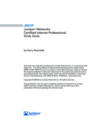
Converged Packet TransportWhite PaperExecutive SummaryThis white paper summarizes Juniper Networks’ vision for the continuous telecommunications shift from circuit to packet.The challenge of building a cost-efficient and survivable packet-optimized transport layer is studied from different angles,including technology progress, industry experience, and economic incentives. This paper explores the long-term effects ofdata convergence and presents the case for migration toward transport based on the next-generation packet platforms,such as Juniper Networks PTX5000.IntroductionModern society is increasingly dependent on connectivity and mobility.In addition to the steady growth of business and consumer data traffic in fixed networks, smart phones are pushing thelimits for data transmission over air, and fixed-mobile convergence is moving voice traffic directly onto IP backbones.The use of traditional landline handsets is quickly going the way of VHS tapes, both at home and in the office. Watchinga movie hosted in the cloud data center, checking corporate email on the run, and placing a call on a fourth-generation(4G) network are very different media experiences, but they employ the same network-layer IP protocol. This “packetrevolution” in the area of communications was not heralded with any press releases but simply issued forth to all butterminate circuit switching at the network’s application level, which had powered all means of connectivity for severaldecades. Whatever we download, see, or hear today is (in most cases) delivered to us in chunks of information ofvariable length—that is, in the form of network packets.Standing in the middle of the “new network” storm, it is easy to imagine the worldwide communications industry to beconverging around packet transport. If the source and the receiver of virtually any human (or robotic) transaction—be ita voice call, HDTV program, traffic light change, or a file download—invariably process and encapsulate data in variablelength units, it is only logical to expect unified core networks to take advantage of the statistical nature of packet flowsto utilize available bandwidth effectively.Amazingly as it sounds, this is not always the case. Transport layers of some of the largest networks in the world stillrun over legacy circuit-based SONET/SDH equipment, which was originally developed in the early 1990s and hasgradually been upgraded over time to cope with increasing voice and data demand. This conservative approach totransport evolution has ensured persistent stability of network services for a large array of applications, and it has keptthe technology pains of early Internet growth away from the majority of business and residential customers. It has alsoresulted in high overhead on top of packet services and has grown to represent one of the largest opportunities forcost reduction in service provider networks. This white paper intends to bridge this gap, discussing the challenges andopportunities for end-to-end packet transport.Legacy Core Infrastructure and Associated CostsRobustness, performance, and cost constraints have historically dictated a unique infrastructure for every digital dataapplication. Voice calls were carried on switched circuits; television broadcasts were delivered using a combinationof satellite and terrestrial distribution networks; and pre-Internet data communications were limited in volume. Notsurprisingly, packet data was often added as an “afterthought” to existing transmission units. At the time that SONET/SDH were introduced as standardized multiplexing protocols, they became an important step forward and a chance toprovide the same underlying network for a large variety of digital data.Their transport-oriented features and protocol neutrality quickly made SONET/SDH the de facto standard for voice,data, and streaming media applications. Since SONET/SDH essentially are a time-based multiplexing/demultiplexingtechnology, application-specific equipment has had to adapt to the hierarchy and groom digital data streams into fixedbandwidth frames available in a limited array of sizes (STS1 to STS192).As a result, by the end of the 1990s, a core network infrastructure typically included a series of SONET/SDH ringscarrying digital data from various sources (see Figure 1). 2015, Juniper Networks, Inc.3
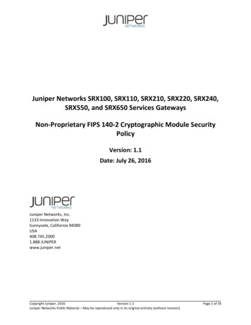
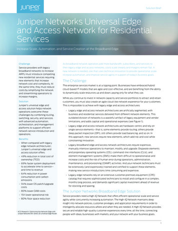
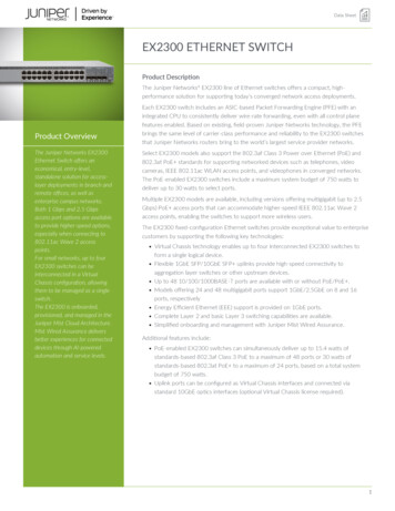
Converged Packet TransportWhite berFiberWDMSDHWDMFigure 1: Legacy core network (IP over SONET over WDM)The protocol neutrality of SONET/SDH allowed ATM, Frame Relay, packet data, and voice calls to be multiplexed overthe common core. Failure recovery was usually done with linear Automatic Protection Switching (APS) or ring-basedprotection [1]. A wavelength-division multiplexing (WDM) layer was later added to provide multiple SONET/SDH signalswith the ability to share physical media.However, the payload filling the SONET/SDH containers has changed dramatically over time.Voice and video delivery have migrated to an all-IP infrastructure, as did the formerly multiprotocol data networks. Inmany cases, different digital applications have still maintained independent distribution paths, but internally they nearlyalways represent data in packet form.When packetized traffic traverses the SONET/SDH backbone, bandwidth loss from adaption to fixed-size time-divisionmultiplexing (TDM) containers and envelopes can be relatively high. For instance, terrestrial video transport in the U.S.typically uses 270 Mbps video circuits, which does not fit cleanly into the TDM bit rates [2]. For this reason, only two 270Mbps signals can fit into an OC-12 circuit, instantly wasting about 10 percent of available bandwidth. However, each 270Mbps video signal is itself a container that can carry compressed SD or HD streams wrapped into an MPEG-2 transportenvelope (and possibly multiplexed to form a DVB/ASI signal). The end result is that only 60 percent or less of linebandwidth is available to the actual MPEG video stream compared to what could be delivered over a native packetoriented transport (for example, Ethernet over WDM). This property of TDM transport is called “grooming inefficiency.”Elastic data sources (such as IP flows or Layer 2 Ethernet trunks), on the other hand, can adapt themselves to fixed-sizecontainers and fit into a SONET/SDH hierarchy fairly well. When running IP/MPLS traffic over SONET within High-LevelData Link Control (HDLC) framing, effective “goodput” ranges from 94 to 97 percent [3]. Nevertheless, since any givenlink of a fixed bandwidth is rarely utilized to full capacity, this uncovers yet another downside of TDM transport. All TDMequipment classes cannot detect and multiplex individual packets, so a virtual circuit may run full even if there is plentyof bandwidth available in the same path—an effect called “lack of statistical multiplexing.”Figure 2: Traffic distribution (24-hour period) at mobile and fixed nodes (source: IST NOBEL)When running variable-rate traffic over the network backbone, efficiency can be vastly improved with multiplexingat the packet level. Looking at the example in Figure 2, normalized traffic dynamics are shown for mobile (variety ofsources) and fixed network nodes [4]. Tidal-chart time scales of dissimilar traffic types make statistical multiplexinga very effective instrument in optimizing the core capacity, as an unused network path can be filled with traffic sharingthe same direction. This includes (but is not limited to) multiplexing of wireline and wireless data, traffic originating inregions within different time zones, packet flows with distributed (peer-to-peer) or centralized (data center-bound)affinity, and so on. 2015, Juniper Networks, Inc.4
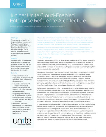
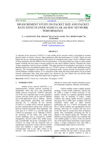
Converged Packet TransportWhite PaperTherefore, in the network where traffic running over SONET/SDH transport is predominantly packet-based, TDMtransport itself represents an overhead that can be quantified in terms of bandwidth loss. Although the exact figure ishighly dependent on network topology and time-bound traffic distribution, it would be safe to conclude that migrationfrom circuit to packet-based transport alone can reclaim a significant percent of the bandwidth otherwise wasted dueto grooming and multiplexing deficiencies. Since packet networks typically employ dynamic redundancy (such as MPLSfast reroute or Ethernet link aggregation group), wavelength utilization can be further improved with fast path restorationsuperseding legacy circuit-level (1:1) path protection [5].To get an idea of what the savings might be, we can think about a typical optical transport network with 80 10 Gbpschannels in its transmission layer. Considering the conservative case, migrating this network from TDM to a nativepacket-based architecture might recover over half of the total bandwidth and provide an immediate opportunity toresell the spare transit capacity. With wholesale IP prices ( per Mbps per month) ranging from below 10 in New Yorkto as high as 80 in Mumbai [6], filling the unused capacity goes way further than ordinary “savings.” It means that anupgrade toward an all-packet transport could pay for itself many times over.IP/MPLS Router Interfaces(1) GbE, VSR/SR(2) GbE, LR(3) 10GbE, LR(4) POS, VSR/SR(5) POS, LR(6) 10GbE WAN Phy, SR(7) POS, colored LH/ULHIP/MPLSservices1/2/3/4/5IP/MPLS Router1234567Ethernetservices11Ethernet Switch Interfaces(1) GbE, VSR/SR(3) 10GbE, LR(6) 10GbE, WAN Phy, SREthernetSwitch68888cdCircuitservicesSONET/SDH Switch Interfaces(8) STM-x, SR(9) STM-x, colored icesa/bab81ba/b(R)OADMddWDM Layer(a) Transponder(b) Muxponder(c) WDM Terminal(d) Optical Fiber(e) Optical Line Amplifier (optional)(f) Dispersion Compensation Filter (optional)(g) Dynamic Gain Equalizer (optional)(h) Regenerator (optional)e,f,g,hdFigure 3: Interface interconnect map in the legacy transport architectureWhile the benefits of removing the legacy SONET/SDH layer are fairly straightforward, one can legitimately ask whethera dedicated transport layer is required.The traditional packet service architecture (Figure 3) has long included an option for interconnecting edge devices (IP/MPLS service routers or Ethernet switches) directly over dark fiber via long-range transceivers. This architecture waslater enhanced with a Packet over DWDM option, where colored lasers are provisioned either directly on the servicesrouter or via a WDM transponder, allowing wavelength-level signal separation. Such an approach allows multiple packetnetworks to share the same fiber capacity, with spare lambdas relegated for legacy TDM transport.To make a decision about whether the dedicated transport layer is needed, it is useful to check Table 1, where runningpacket services over dark fiber represents the simplest core architecture. In such an instance, a single IP/MPLS networkcan span over a vast geographical region and deliver L2 and L3 traffic to Internet and VPN customers. An attempt toextend this model into multiple packet networks sharing the same topology would require wavelength-level separationin the WDM layer. With a core based on Packet over DWDM, every overlay network has to be represented with atleast one physical port at each node, and the number of wavelengths limits the total number of colocated networks.For example, a metro network might use one wavelength, a long-haul core network might use another, and a legacyTDM network might use a third. Ultimately, the entire wave plan would have to be tailored according to the network’scolocation needs, while also factoring resiliency and traffic growth needs—indeed a very complex task. 2015, Juniper Networks, Inc.5
Converged Packet TransportWhite PaperTable 1: Packet Delivery Options With and Without a Dedicated Transport LayerTransport TechnologySeparation er ofOverlay Networks(Independent ServicePlanes)None (packet over dark fiber)N/AN/AGoodSingle (packet) networkPacket over wave over DWDMWavelength-based2.5 Gbps, 10 Gbps, 40Gbps, 100 GbpsGoodLowPacket over SDH over DWDMTDM channelsSDH hierarchyVery PoorHighPacket over OTN over DWDMTDM subchannelsNxODU0 hierarchyModerateVery highPacket over packet over DWDMLabel-switched pathAny rate (stat mux)Very goodVery highThe fact that wavelength-based transport can easily run out of available wavelengths spurs the need for the electricaltransport layer, where an additional level of multiplexing allows for growth of services beyond the limits of a wavelengthplan. At this high end of the backbone design, bandwidth utilization also matters the most, strongly calling for departurefrom legacy SONET/SDH topologies.Therefore, a new, packet-oriented architecture is desirable for the transport role. Such a dedicated transport layer ismostly needed in the backbones of Internet service providers (ISPs) and large enterprises, and it represents the focaltopic of this document.Transport Layer ComponentsControl PlaneThe term “control plane” in the transport layer describes the collective intelligence that drives route computation, failurerecovery, and traffic management decisions. The oldest transport layer in use (SONET/SDH) is also the simplest one.Being widely available commercially, SONET/SDH transport provides only circuit services with available 1:1 protectionand rudimentary control plane capabilities.The growing mismatch between the needs of packet services and static circuit provisioning has long sparked interestin alternative technologies such as Frame Relay, ATM, and Dynamic Packet Transport (DPT). More recent “transportrunner-up” efforts have included Provider Backbone Bridge-Traffic Engineering (PBB-TE) and Transport MPLS (T-MPLS).Without going into the details of why those technologies eventually failed to displace SONET/SDH (or even get intowidespread adoption), it is interesting to note that their control plane development took the following general steps:1. Pre-engineeredConnections2. Failoverprotection3. Dynamic pathcomputation4. TrafficengineeringAlthough many transport technologies stopped short of going the full way, the time and effort that went intodevelopment of their control plans was typically very significant. Moreover, efforts to replace or modify a wellestablished framework have almost invariably resulted in duplication of effort and compatibility issues, which makes thecontrol plane’s de jure (standardization) and de facto (interoperability) statuses extremely important for network design(Table 2).Table 2: Common Transport Technologies with Control PlanesTransportTechnologyPre-Engineered PathPath RestorationControl PlaneStandardization/AdoptionSONET/SDHYes, TDM-basedNoStaticYes/Widely usedATMYes, cell-based PVCNoPNNIYes/Gradually phased outOTNYes, TDM-basedBased on MPLSGMPLSEarly stage/Early stageMPLS/MPLS-TPYes, packet LSPFast rerouteMPLSYes/Widely used 2015, Juniper Networks, Inc.6
Converged Packet TransportWhite PaperOn the requirement side, the modern transport control plane must support the following features: Path protection for unicast and multicast traffic (ability to fail over to prearranged path) Path restoration for unicast and multicast traffic (ability to restore reachability after multiple failures) Traffic engineering (dynamic bandwidth allocation, link affinity) Prioritization and preemptive connection treatmentWhile this list looks deceptively simple, the effort required to fulfill all of the requirements on it should not beunderestimated. Moreover, the basic principles of sharing link states, path computation, and traffic engineering areessentially the same, and they have been extensively refined in the industry over the last decade. The rules of convergentevolution dictate similar solutions for similar problems, which means that many transport technologies entered life with“simple” pre-engineered services, only to discover later that the more complex capabilities (such as path computationand restoration) are calling for functions already implemented elsewhere.Decoupling the control and data planes offers an elegant solution to this problem. Connection-oriented, abstract pathestablishment, and manipulation appear to be universally useful for all transport equipment types, regardless of thetechnology underpinning the data plane. Once developed and accepted by the industry, they represent an achievementtoo large to displace.This is why, at present, MPLS appears to be the control plane of choice. There is little indication of transport networkswidely adopting any other protocol stack in the near to midterm future.Data PlaneAs discussed previously, the transport data plane can consist of virtual circuit (VC)-oriented or packet-orientedhardware. Regardless of the underlying technology, the transport data plane must have the hardware suitable for labelstack manipulation and QoS support. Multicast replication is an optional, but highly desired feature as well. On the longhaul interface side, strong optical (LH/ULH) integration is required to reduce dependency on external transceivers andprovide preemptive path restoration based on optical signal quality prior to error correction.The choice between circuit and a packet-based data plane is pivotal to transport network efficiency and cost, so it helpsto mind the difference between alternatives from various perspectives (Table 3).Table 3: Data Plane OptionsTechnologyMPLS stack supportQoSMulticastRelative cost per portOCSGMPLSOne classRudimentaryLower (50-90%)OTNGMPLSOne classRudimentaryMedium (80-110%)PacketMPLS/G-MPLSEight classesFull supportHigher (100-130%) 2015, Juniper Networks, Inc.7
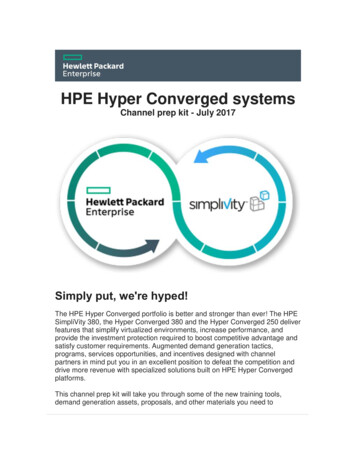
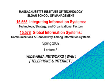
Converged Packet TransportWhite PaperFault Tolerance and ManageabilityWhen evaluating vendor claims about transport robustness, it is useful to keep the main reasons for network failures incheck. Aside from human errors, fault descriptions can be broadly sorted into hardware, software issues, and link failures.Considering legacy SONET/SDH switches operating at Layers 1 and 2 of an OSI network model [OSI] to be the referencesystems, it is interesting to gauge them against more complex devices. As expected, according to data reported by ISTNOBEL, the total FIT rate (number of failures for 109 hours) does grow between L1, L2, and L3 platforms (Figure 4).8%7%6%5%4%3%2%1%0%Layer 1Layer 2SoftwareLayer 3HardwareFigure 4: The number of equipment components in failure at least one time per year (source: IST NOBEL)Yet, the ratio of hardware-specific failures does not change between L1/L2 (for example, SONET/SDH) and L3 (forexample, IP/MPLS) equipment significantly, so the observed difference is mostly driven by software. This makes sensebecause L3 equipment traditionally provides more complex services (Internet routing, VPN, multicast, etc.) comparedto the static switching typical of SONET/SDH transport. The extra functionality is driven by software code in the controlplane, which, together with an increased variety of use cases, can negatively affect reliability.However, the software reliability gap reasonably decreases once L1/L2 equipment is retrofitted with a dynamic controlplane that employs comparable or the same software complexity as the regular MPLS stack.In particular, any TDM switches (such as OTN platforms) operating under GMPLS control are not likely to offernoticeable software-driven reliability advantages over their packet-based transport counterparts. Any such differencesbetween equipment from various vendors (if observed) should be attributed to software quality (for example, nonstoprouting [7]), coding discipline, and regression methodology [8] rather than genuine equipment class differences.In addition, it should also be noted that MPLS equipment in a transport profile has a limited function set compared to“service-oriented” IP/MPLS networks and should experience lower failure rates. Moreover, when integration of serviceand transport IP/MPLS domains is not required, a packet transport platform can operate in its own plane with adedicated management stratum and remain unaffected by service-level IP or MPLS domains. In this case, a separateNetwork Layer operates its own label stack and does not maintain routing adjacencies with client IP and MPLS networks(Figure 5). From a client standpoint, transport network remains transparent and looks like a tunnel to upper layers. 2015, Juniper Networks, Inc.8
Converged Packet TransportWhite PaperService Network 2SN 2.2Service Network 3SN 3.1Service Network 1SN 1.2Service Network 2SN 2.3TN2TN3Service Network 3SN 3.2TN4Transport Network NMSFiber NetworkTransport NetworkService Network 1SN 1.1TN1TN6TN5Service Network 2 IPService Network 2:SN 2.1Service Network 2 IPService LSP1Service LSP2Service LSPnTransport LSPService LSP1Service LSP2Service LSPnService Network 2 LSPnService Network 2SN 2.4Service Network 2 LSPnIP/MPLS traffic flowFigure 5: Sample packet transport network with independent control planeFinally, some aspects of reliability of modern L3 equipment might actually improve over legacy SONET/SDH parameters.One such aspect is detection and processing of link failures.In “classic” SONET/SDH architecture, the long-haul transponders are external to the electrical exchange switch (EXC),and details of the optical plane operation remain hidden from the SONET layer. Optical signal degradation (if detected)ultimately manifests itself in the SONET/SDH overhead sections and a faltering link is declared down. This declarationtriggers reconvergence at TDM (if APS enabled) and packet layers (if TDM restoration failed). Thus, failure recoveryfunction exists on two layers and requires a spare path for backup. Adding agile photonic layer into equation make thepicture even worse – now every path needs a spare circuit on both optical and TDM layers and traffic is triple-protect
Converged Packet Transport White Paper 2015, Juniper Networks, Inc. Figure 1: Legacy core network (IP over SONET over WDM) The protocol neutrality of SONET/SDH allowed ATM, Frame Relay, packet data, and voice calls to be multiplexed over the common core. Failure recovery was usually done with linear Automatic Protection Switching (APS) or .