Transcription
Voltage Stability for UndergraduatesUniversity of Minnesota Power GroupInternet-Based Monthly SeminarJuly 1, 2008Carson W. Taylor, Seminar LeaderBonneville Power Administration (retired)cwtaylor@ieee.org
Objective (from Ned Mohan) If our undergraduates were to take just onecourse in Power Systems before graduating, whatshould they learn about Voltage Stability in 1-3lectures? Assume that they have already studiedTransmission Line Characteristics, Power Flow,Transformers, HVDC and FACTS, and SynchronousGenerators in their previous lectures.2
Motivating Questions What is voltage stability? How is it related to angle (synchronous) stability? What are types of voltage instability and timeframes? What are countermeasures? Is it static or dynamic phenomena? Can it be analyzed via static power flow simulation? What is role of active and reactive powertransmission?3
Approach Emphasize physical phenomena Emphasize dynamics Examples of actual events Relate to other power system topics, controlengineering, power electronics, electromechanicalenergy conversion, math4
An Important Industry ProblemVoltage collapse is still the biggest single threatto the transmission system. It’s what keeps meawake at night.Phil Harris, PJM President and CEO, March 2004PJM (Pennsylvania, New Jersey, Maryland — now expanded to theMidwest) is one of the world’s largest power transmission organizations.5
What is Voltage Stability (Instability)? Voltage stability is load stability Angle (synchronous) stability is generator stability Radial feed from large system to load — purevoltage stability concernvLoad Radial feed from remote generator to large system— pure rotor angle stability concernE δ Angle and voltage stability phenomena interact: e.g., rotor angle swings cause voltage swings Two time frames: short- and long-term stability Typically involves a load area of a power system,but can cascade to blackout larger area6
What Are Voltage Instability Mechanisms? Part of a power system is heavily loaded and thenone or several important transmission lines trip: Voltages will sag Many loads are voltage sensitive and thus will reduce,which is stabilizing If transmission outages are because of short circuits,induction motors will slow down and require more reactivepower, and perhaps stall Regulating mechanisms try to restore power tomeet demand at normal voltage Load restoration further stresses and overloadspower system, resulting in voltage instability andcollapse — voltage stability is load stability, relatedto load demand versus load supply capability7
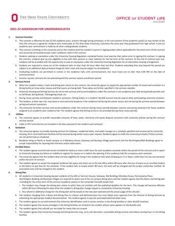
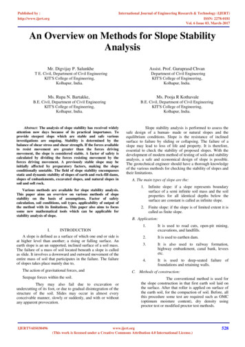
Short-Term Voltage Stability Short term associated with induction motors,especially residential air conditioners and heat pumps: Short circuits slow low-inertia air conditioner compressormotors, requiring high current similar to starting current Motors may stall, preventing fast voltage recovery aftershort circuit clearing Compressor motors are tripped only after overheating, 3–15seconds after stalling Cascading of motor stalling within few seconds Recall induction motor torque-speed curves Recall motor electrical torque is proportional tovoltage squared How to model single-phase motors?8
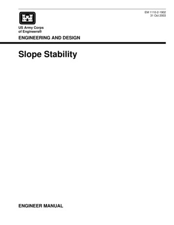
Induction Motor Torque-Speed CurvesMechanicalload torqueElectricaltorqueTorque-speed curve for 5 HP, single-phase residential central airconditioner compressor motor. Compressor mechanical torque is nearlyconstant with respect to speed but increases with ambient temperature.Source: GE9
Induction Motor Torque/Current-Speed CurvesHigh current at low power factor as motordecelerates during short circuit.10
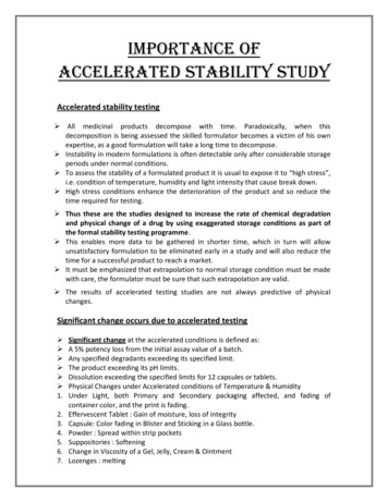
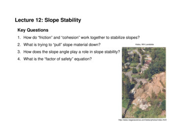
Short-Term Voltage Stability Example Phoenix, Arizona area on 29 July 1995 Saturday afternoon, 112 F, 44 C 230-kV capacitor bank fault with delayed clearing: Five 230-kV lines tripped After 3 seconds, two 230/69-kV transformers tripped Stalling of air conditioning motors: About 2100 MW of load lost 20 seconds for voltage recovery High reactive power output from generatorsprevented collapse Generators might trip during severe events causingcomplete blackout (accidents waiting to happen,dozens of control and protection devices)11
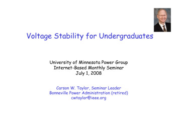
Short-Term Voltage Stability: Phoenix AreaResidential voltage: 58.4 volts RMS minimum, 15.8 seconds belowthreshold. A/C tripping by thermal protectors probably started around ten seconds.140120Volts100806040200024681012Time - seconds1416182012
Short-Term Voltage Stability: Phoenix AreaPalo Verde nuclear power plant reactive power outputs (megavar)13
Long-Term Voltage Stability Long term typically associated with voltageregulation by tap changers close to loads: Voltage regulation restores voltage-sensitive loads Time frame of tens of seconds, minutes Long-term instability also caused by constantenergy loads such as thermostatically controlledheating load: Loss of load diversity; more heaters must be on tosatisfy energy demand Time frame of many minutes Load restoration may cause generator fieldcurrents to exceed time-overload capability: Overexcitation limiters on generator voltage regulators14
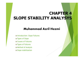
Long-Term Voltage Instability: SouthSweden/Denmark Blackout, 23 Sept. 2003 In Sweden, two 400-kV lines and four nuclear unitsout for maintenance; system adjusted At 12:30, loss of a 1200 MW nuclear unit insoutheastern Sweden At 12:35, double bus-bar fault in southwesternSweden causing loss of two 900 MW nuclear units: N-3 event Voltage instability with separation 97 seconds later: Blackout of Southern Sweden and eastern Denmark (Malmö,Copenhagen) 4700 MW load lost in Sweden, 1850 MW in Denmark15
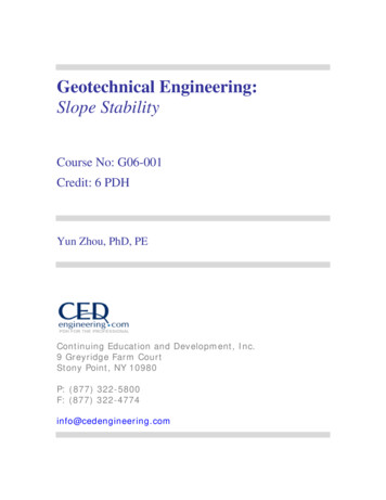
South Sweden/Denmark Blackout, 23 Sept.200312:3512:3612:37Odensala on stable side following separation at 97 seconds16
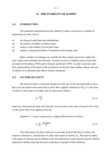
South Sweden/Denmark Blackout, 400/130-kVTransformer Tap Changing at Simpevarp400-kV Side Voltage12:35Tap Changer Position12:3712:3512:37Source: Gajiĉ, Karlsson, Kockott, “Advanced OLTC Control to Counteract Power System VoltageInstability,” ABB web site.17
Voltage Stability Dynamics Voltage stability involves large disturbance, nonlinear, discontinuous dynamics Load restoration concepts understood from firstorder differential equations (highly oversimplified) Stabilizing actions must be timely to ensure Regionof Attraction to post-disturbance operating point(equilibrium point) State variables are slip (s), turns ratio (n), and loadconduction (G)18
Load Dynamics/Region of AttractionP, QVTap changer dynamicsregulating low side voltageVLInduction motordynamicsConstant energyload dynamicsMOtherloadsLoad dynamics are basically first orderdsMotor2Hω Po PedtTTTE V dn Po Po L dt Vo α V dG Po Go L dt Vo Tap changer2Constant energy19
Load DynamicsPower SystemP, QVTap changer dynamicsregulating low side voltageVLInduction motordynamicsConstant energyload dynamicsMOtherloadsPPre-disturbance curvePOPower demand12Final postdisturbance curveDisturbance curvexsxustableunstables, n, or G (state variable)20
ExerciseIntegrate both sides of one or more of the differentialequations and draw block diagram using integrators. Oneblock is the power system with state variable as input andelectrical power as output. Explain what happens for adisturbance in the power system (short circuit for motorload), including how equilibrium is reached. Whathappens if tap changer limits are reached?Compare previous figure with equal area diagram forangle stability. What must balance for equilibrium?The block diagram is similar to how an analog computeris programmed, but also applies to numerical integrationused nowadays for time domain simulation.21
Three Aspects of Voltage Stability1. Load as seen from the bulk power system — loadrestoration dynamics: Motors, tap changers, constant energy/thermostats2. Voltage control at generators and in network: Generator AVRs Switched capacitor banks, SVCs, STATCOMS3. Network ability to transfer power from point ofproduction to point of consumption: Voltage drop mainly due to reactive power transfer Reactive power loss (I 2X) mainly due to active powertransfer22
Voltage Instability Countermeasures Engineers must economically ensure reliable powerdelivery. Economical solutions often control based. Basic strategy: Apply shunt capacitor banks,mainly in distribution and load area transmissionsubstations to minimize reactive powertransmission, allowing automatically controlledreactive power reserve at generators. Design and operate transmission network for high, flatvoltage profile to minimize I 2X losses.23
Further Voltage Instability Countermeasures Switched shunt capacitor banks: Local or wide-area control Series capacitor banks Static var compensators or STATCOMs for shortterm voltage stability: Large transmission devices versus multiple distributiondevices? Transmission-side voltage control at generators similarto SVC Tap changer blocking, reverse control, or repositioningfor upstream-side voltage sag Load shedding: Local undervoltage or wide-area24
Voltage Stability Definitions (IEEE/CIGRE) Voltage stability is the ability of a power system tomaintain steady voltages after a disturbance. Mustmaintain or restore equilibrium between connectedload, and load supply from the power system.Instability is progressive fall or rise of voltages atsome buses: Parallel definitions for angle and frequency stability. Whatmust be in equilibrium? The driving force for voltage instability is usually theloads. After a disturbance, load power restoration isattempted by motor slip adjustment, tap changing, andthermostats. Short-term, long-term voltage instability Instability is runaway, positive feedback phenomena25
Voltage Stability Definitions A power system at an operating state is voltagestable if following a disturbance, voltages nearloads approach stable post-disturbance equilibriumvalues: Within region of attraction of post-disturbanceequilibrium after switching and control actions Stability may be due to destabilizing controls reachinglimits, or other actions such as load disconnection Voltage instability may cause voltage collapse orabnormally high voltages26
Voltage Stability Definitions A power system undergoes voltage collapse if postdisturbance equilibrium voltages are belowacceptable limits: Voltage collapse may be total (blackout) or partial Voltage collapse may be due to voltage or angle instability Inadequate voltage support may cause angle instability Underside of P-V curve is partial voltage collapsewith power uncontrollability Adding load reduces voltage (normal), but reduces totalpower (abnormal) Stable operation possible with voltage-sensitive loads Distinguish between load power at nominal voltageand load power consumed at actual voltage27
Stable or Unstable? Western France, Jan. 19876 minutes28
Voltage Security, Control Centers Voltage security quantified by margins or indices Candidate margins or indices? Voltage monitoring sufficient? What else should be monitored? Answer: reactive powerreserves Voltage secure for a specified direction of stresswhen the margin for credible contingencies islarger than reliability criteria margin: Example: 5% power margin determined by on-line, closeto real-time simulation29
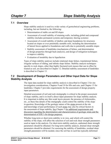
Generator Time-Overload Capability Field circuit overload usually occurs first, butarmature current overload also important: Field current overload caused by outages and loadrestoration is key mechanism of long-term voltageinstability Field current (generator excitation) closely related toreactive power output. But armature current overloadalso usually reduced by field current reduction (reactivepower rather than active power typically reduced). Generator automatic voltage regulator includeslimiter of field current time-overload: Time frame is tens of seconds Limiter set inside time-overload capability required bystandards30
Generator Time-Overload Capability31
Voltage Stability Simulation Dynamic simulation essential for short-termvoltage stability (as for angle stability): Dynamic models for motor load, generators, SVCs Dynamic simulation also valuable for long-termvoltage stability: Coordination of controls Greater accuracy and insight Power flow program static simulation forapproximate analysis and screening: P-V and V-Q curves widely used32
P-V, S-V Curves Voltage stability is dynamic phenomena: Automation of individual power flow cases. P-V curve: power import increase to load area bydecrease in load area generation S-V curve: proportional increase in load at areabusses at constant power factor Generation redispatch required as load or importis substantially increased Possible power flow convergence problems near“nose”: Avoided by dynamic simulation of load ramp33
P-V Curves: Two Concepts (Van Cutsem) Post-disturbance loadability Secure operating point34
P-V (nose) Curve: Post-Disturbance Loadability Test post-disturbance robustness and margin fromoperating point or base case: Must iterate to find transfer limit Contingencies simulated without system basePPmax35
P-V Curve: Secure Operating Limit Binary search most efficient method: Can use dynamic simulation for greater accuracyPre-contingency cases w/ system readjustmentVStartStable (converged)UnstablePmarginPlim PmaxP36
Q-V, V-Q Curves x-y, not y-x terminology. x is independent variable. Q-V curve: proportional increase in reactive powerload at area busses. Similar to P-V curve methods. Reactive power increase tests area voltage stability Area busses stressed uniformly, weak points identified Generation redispatch not necessary V-Q curve: set of scheduled voltages at a singlebus (fictitious PV/synchronous condenser bus): V is independent (x) variable, Q injection is dependent Tests bus strength and helps determine reactive powercompensation need. Robust convergence. S
especially residential air conditioners and heat pumps: Short circuits slow low-inertia air conditioner compressor motors, requiring high current similar to starting current Motors may stall, preventing fast voltage recovery after short circuit clearing Compressor motors are tripped only after overheating, 3–15 seconds after stalling Cascading of motor stalling within few .