Transcription
RaneNoteLINKWITZ-RILEY CROSSOVERS: A PRIMERLinkwitz-Riley Crossovers:A Primer Linkwitz-Riley Background 1st-Order Crossover Networks Butterworth Crossovers 2nd to 4th-Order Linkwitz-Riley Crossovers 2nd to 8th-Order Phase, Transient & Power ResponsesIntroductionIn 1976, Siegfried Linkwitz published his famous paper[1] on active crossovers for non-coincident drivers. Init, he credited Russ Riley (a co-worker and friend) withcontributing the idea that cascaded Butterworth filtersmet all Linkwitz’s crossover requirements. Their effortsbecame known as the Linkwitz-Riley (LR) crossoveralignment. In 1983, the first commercially availableLinkwitz-Riley active crossovers appeared from Sundholm and Rane.Today, the de facto standard for professional audioactive crossovers is the 4th-order Linkwitz-Riley (LR-4)design. Offering in-phase outputs and steep 24 dB/octave slopes, the LR-4 alignment gives users the necessary tool to scale the next step toward the elusive goalof perfect sound. And many DSP crossovers offer an8th-order Linkwitz-Riley (LR-8) option.Before exploring the math and electronics of LRdesigns, it is instructional to review just what Linkwitz-Riley alignments are, and how they differ fromtraditional Butterworth designs.Dennis BohnRane CorporationRaneNote 160 2005 Rane CorporationLinkwitz-Riley-
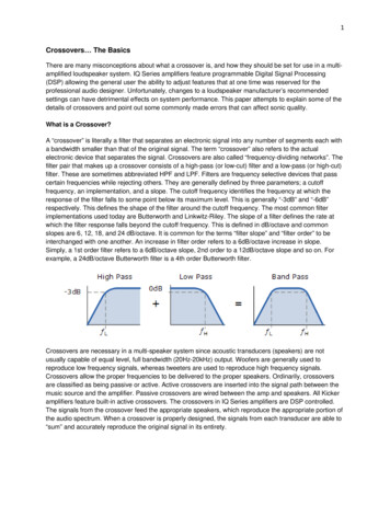
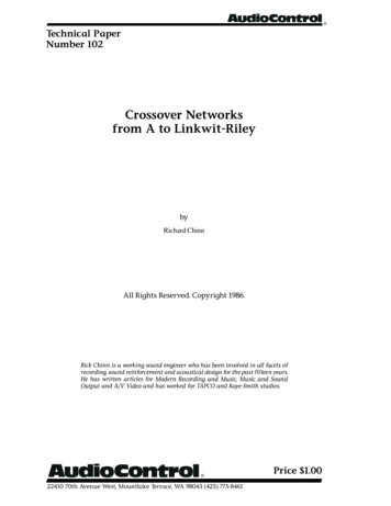
Linkwitz-Riley Crossovers: BackgroundSiegfried Linkwitz and Russ Riley, then two HewlettPackard R&D engineers, wrote the aforementioned paper describing a better mousetrap in crossover design.Largely ignored (or unread) for several years, it eventually received the attention it deserved. Typical of trulyuseful technical papers, it is very straightforward andunassuming: a product of careful analytical attentionto details, with a wonderfully simple solution.It is seldom whether to cross over, but rather, how tocross over. Over the years active crossovers proliferatedat a rate equal to the proverbial lucky charm.In 1983, a 4th-order state variable active filter [2]was developed by Rane Corporation to implement theLinkwitz-Riley alignment for crossover coefficients andnow forms the heart of many analog active crossoverdesigns.A Perfect CrossoverMother Nature gets the blame. Another universe,another system of physics, and the quest for a perfectcrossover might not be so difficult. But we exist hereand must make the best of what we have. And what wehave is the physics of sound, and of electromagnetictransformation systems that obey these physics.A perfect crossover, in essence, is no crossover atall. It would be one driver that could reproduce allfrequencies equally well. Since we cannot have that,second best would be multiple speakers, along the sameaxis, with sound being emitted from the same point,i.e., a coaxial speaker that has no time shift betweendrivers. This gets closer to being possible, but still iselusive. Third best, and this is where we really begin,are multiple drivers mounted one above the other withno time shift, i.e., non-coincident drivers adjustedfront-to-rear to compensate for their different points ofsound propagation. Each driver would be fed only thefrequencies it is capable of reproducing. The frequencydividing network would be, in reality, a frequency gate.It would have no phase shift or time delay. Its amplitude response would be absolutely flat and its roll-offcharacteristics would be the proverbial brick wall.(Brings a tear to your eye, doesn’t it?)DSP digital technology makes such a crossover possible, but not at analog prices demanded by most working musicians.Linkwitz-Riley- Linkwitz-Riley CrossoverWhat distinguishes the Linkwitz-Riley crossover design from others is its perfect combined radiation pattern of the two drivers at the crossover point. StanleyP. Lipshitz [3] coined the term “lobing error” to describe this crossover characteristic. It derives from theexamination of the acoustic output plots (at crossover)of the combined radiation pattern of the two drivers(see Figures 1 & 2). If it is not perfect the pattern formsa lobe that exhibits an off-axis frequency dependent tiltwith amplitude peaking.Interpretation of Figure 1 is not particularly obvious. Let’s back up a minute and add some more details.For simplicity, only a two way system is being modeled.The two drivers are mounted along the vertical centerof the enclosure (there is no side-to-side displacement,i.e., one driver is mounted on top of the other.) Allfront-to-back time delay between drivers is corrected.The figure shown is a polar plot of the sideview, i.e., theangles are vertical angles.It is only the vertical displacement sound field that isat issue here. All of the popular crossover types (constant voltage [4], Butterworth all-pass [5], etc.) are wellbehaved along the horizontal on-axis plane. To illustrate the geometry involved here, imagine attachinga string to the speaker at the mid-point between thedrivers. Position the speaker such that the mid-point isexactly at ear level. Now pull the string taut and holdit up to your nose (go on, no one’s looking). The stringshould be parallel to the floor. Holding the string tight,move to the left and right: this is the horizontal onaxis plane. Along this listening plane, all of the classic crossover designs exhibit no problems. It is whenyou lower or raise your head below or above this planethat the problems arise. This is the crux of SiegfriedLinkwitz’s contribution to crossover design. After allthese years and as hard as it is to believe, he was thefirst person to publish an analysis of what happens offaxis with non-coincident drivers (not-coaxial). (Othersmay have done it before, but it was never made publicrecord.)Figure 1a represents a side view of the combinedacoustic radiation pattern of the two drivers emittingthe same single frequency. That is, a plot of what isgoing on at the single crossover frequency all along thevertical plane. The pattern shown is for the popular 18dB/octave Butterworth all-pass design with a crossoverfrequency of 1700 Hz and drivers mounted 7 inchesapart1.
Time Corrected SoundPropagation PlaneTime Corrected SoundPropagation Planeationcell. Can3Axis0 dB1. On-Axis2. Pe 3 dBPeakingakingAxisOn-AxisNo PeakingCancellationAxis3.ntiolaelncCaCombined AcousticRadiation PatternisAxCombined AcousticRadiation PatternisAxniolatcelnCaFigure 1a.Figure 2. Linkwitz-Riley radiation response at crossover. 32. Peaking Axisisio n3. CancellatAmplitude (dB)Ax01. On-Axis1700 HzFrequency (Hz)Figure 1b. Butterworth all-pass design radiation pattern atcrossover.What is seen is a series of peaking and cancellationnodes. Back to the string: holding it taut again andparallel to the floor puts you on-axis. Figure 1a tells usthat the magnitude of the emitted 1700 Hz tone willbe 0 dB (a nominal reference point). As you lower yourhead, the tone increases in loudness until a 3 dB peak isreached at 15 degrees below parallel. Raising your headabove the on-axis line causes a reduction in magnitudeuntil 15 degrees is reached where there is a completecancellation of the tone. There is another cancellationaxis located 49 degrees below the on-axis. Figure 1bdepicts the frequency response of the three axes forreference.For a constant voltage design, the response looksworse, having a 6 dB peaking axis located at -20 degrees and the cancellation axes at 10 and -56 degrees,respectively. The peaking axis tilts toward the laggingdriver in both cases, due to phase shift between thetwo crossover outputs.The cancellation nodes are not due to the crossoverdesign, they are due to the vertically displaced drivers. (The crossover design controls where cancellationnodes occur, not that they occur.) The fact that theLinkwitz-Riley-
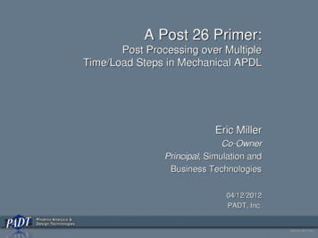
n AxisellatioCancntiolaelncCaOn AxisPeaking AxisisAxFigure 3. Butterworth all-pass crossover stage-audience relationship.CaCaisAxiontaellncncOn AxisellationAxisFigure 4. Linkwitz-Riley crossover stage-audience relationship.drivers are not coaxial means that any vertical deviation from the on-axis line results in a slight, but verysignificant difference in path lengths to the listener.This difference in distance traveled is effectively aphase shift between the drivers. And this causes cancellation nodes — the greater the distance betweendrivers, the more nodes.In distinct contrast to these examples is Figure2, where the combined response of a Linkwitz-Rileycrossover design is shown. There is no tilt and no peaking — just a perfect response whose only limitation isthe dispersion characteristics of the drivers. The maincontributor to this ideal response is the in-phase relationship between the crossover outputs.Linkwitz-Riley- Two of the cancellation nodes are still present, butare well defined and always symmetrical about theon-axis plane. Their location changes with crossoverfrequency and driver mounting geometry (distancebetween drivers). With the other designs, the peakingand cancellation axes change with frequency and driverspacing.Let’s drop the string and move out into the audienceto see how these cancellation and peaking nodes affectthings. Figure 3 shows a terribly simplified, but not tooinaccurate stage-audience relationship with the characteristics of Figure 1 added.The band is cooking and then comes to a musicalbreak. All eyes are on the flautist, who immediately goesinto her world-famous 1700 Hz solo. So what happens?The people in the middle hear it sweet, while those upfront are blown out of their seats, and those in the backare wondering what the hell all the fuss is!Figure 4 shows the identical situation but with theLinkwitz-Riley characteristics of Figure 2 added. Nowthe people in the middle still hear everything sweet,but those up front are not blown away, and those in theback understand the fuss!I think you get the point.Now let’s get real. I mean really real. The system isn’ttwo way, it is four way. There isn’t one enclosure, thereare sixteen. No way are the drivers 7 inches apart — try27 inches. And time corrected? Fuhgeddaboudit.Can you even begin to imagine what the verticaloff-axis response will look like with classic crossoverdesigns? The further apart the drivers are, the greaterthe number of peaks and cancellations, resulting in amulti-lobe radiation pattern. Each crossover frequencyhas its own set of patterns, complicated by each enclosure contributing even more patterns. And so on.(For large driver spacing the Linkwitz-Riley designhas as many lobes as other designs, except that thepeaks are always 0 dB, and the main lobe is alwayson-axis.)Note that all this is dealing with the direct soundfield, no multiple secondary arrivals or room interference or reverberation times are being considered. Is itany wonder that when you move your real-time analyzer microphone three feet you get a totally differentresponse?Now let me state clearly that using a Linkwitz-Rileycrossover will not solve all these problems. But it willgo a long way toward that goal.
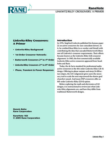
0-3-612 dBAmplitude (dB)-1018dB/-20/ octoct24dB-30/oct-40fo/2foFrequency (Hz)2foFigure 5. Frequency response of 4th-order Linkwitz-Riley crossover.The other outstanding characteristic of the Linkwitz-Riley alignment is the rolloff rate of 24 dB/octave(Figure 5). With such a sharp drop-off, drivers canoperate closer to their theoretical crossover pointswithout the induced distortion normally caused byfrequencies lying outside their capabilities. Frequencies just one octave away from the crossover point arealready attenuated by 24 dB (a factor or about 1/16).The importance of sharp cutoff rate and in-phase frequency response of the crossover circuitry cannot beover-stressed in contributing to smooth overall systemresponse.Linkwitz-Riley crossover characteristics summary:1. Absolutely flat amplitude response throughout thepassband with a steep 24 dB/octave rolloff rate afterthe crossover point.2. The acoustic sum of the two driver responses is unityat crossover. (Amplitude response of each is -6 dBat crossover, i.e., there is no peaking in the summedacoustic output.)3. Zero phase difference between drivers at crossover.(Lobing error equals zero, i.e., no tilt to the polar radiation pattern.) In addition, the phase difference ofzero degrees through crossover places the lobe of thesummed acoustic output on axis at all frequencies.4. The low pass and high pass outputs are everywherein phase. (This guarantees symmetry of the polarresponse about the crossover point.)5. All drivers are always wired the same (in phase).A Linkwitz-Riley crossover alignment is not linearphase: meaning that the amount of phase shift is afunction of frequency. Or, put into time domain terms,the amount of time delay through the filter is notconstant for all frequencies, which means that somefrequencies are delayed more than others. (In technicalterms, the network has a frequency-dependent groupdelay, but with a gradually changing characteristic.)Is this a problem? Specifically, is this an audible“problem?” In a word, no.Much research has been done on this question [69] with approximately the same conclusions: given aslowly changing non-linear phase system, the audibleresults are so minimal as to be nonexistent; especiallyin the face of all of the other system nonlinearities.And with real-world music sources (remember music?),it is not audible at all.State-Variable SolutionOne of the many attractions of the Linkwitz-Riley design is its utter simplicity, requiring only two standard2nd-order Butterworth filters in series. The complexities occur when adjustable crossover frequencies arerequired.After examining and rejecting all of the standardapproaches to accomplish this task, Rane developeda 4th-order state-variable filter specifically for implementing the Linkwitz-Riley crossover. The state-variable topology was chosen over other designs for thefollowing reasons:1. It provides simultaneous high-pass and low-pass outputs that are always at exactly the same frequency.2. Changing frequencies can be done simultaneouslyon the high-pass and
crossover design is shown. There is no tilt and no peak-ing — just a perfect response whose only limitation is the dispersion characteristics of the drivers. The main contributor to this ideal response is the in-phase rela-tionship between the crossover outputs. Linkwitz-Riley- The other outstanding characteristic of the Link- witz-Riley alignment is the rolloff rate of 24 dB/octave (Figure .