Transcription
A New Synthetic Training Environment System Based On AnICT-Approach For Manual Ultrasonic TestingAlvin Yung Boon Chong1, Abdeldjalil Bennecer1, Fredrik Hagglund2, Saarim Siddiqi1, Vassilios Kappatos1,Cem Selcuk1 and Tat-Hean Gan11Brunel Innovation Centre, Brunel University, Abington Hall, Granta Park, Great Abington, Cambridge, CB216AL, United Kingdom2TWI Ltd, Granta Park, Great Abington, Cambridge, CB21 6AL, United KingdomEmail Address: alvin.chong@brunel.ac.ukAbstractTraining to qualify as a manual ultrasonic inspector takes a long time and costs a considerable amountof money. We developed a virtual training environment using an innovative dead-reckoning opticalsensor that yields translational position which offers additional information to operators and examinersalike. The training environment contains a library of test scenarios, shows surface coverage, measuresthe time of inspection, indicates detected defects and provides a performance score. Our test-bed trialresults using a pool of Ultrasonic Test (UT) qualified and unqualified participants on two virtual trainingblocks that contain 2 flaws each reveal 100% detection and an accuracy of 5 mm in locating defects inmore than 50% of the measured defect locations.Keywords: ultrasonic, probability of detection, synthetic training, information and communicationtechnology, optical sensor and tracking system.1. IntroductionManual Ultrasonic Testing (MUT) is a well-established and widely adopted Non-destructive Testing(NDT) technique in engineering industry. However, the reliability of a MUT system depends primarilyon the capability of its key components which mainly comprise of the procedure, the equipment and thepersonnel. While improvements in the former two elements have received considerable attentionamongst different research communities, the latter mainly benefited from comprehensive investigationson the influence of human factors affecting the Probability of Detection (PoD) [1-4]. Moreover, a salarysurvey conducted by Personnel for Quality and Non-destructive Testing (PQNDT) in 2013 revealed thatthe average age for an NDT technician is 46 years old. This is an increase of 3.5 years since 2006 whena similar survey has taken place [5]. This indicates that the existing NDT workforce has an agingdemography which creates a severe shortage of skilled personnel. The increased complexity of1
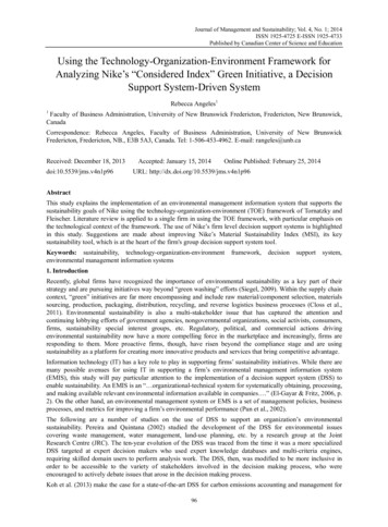
equipment, particularly in ultrasonic testing, and the introduction of new techniques have also led to ahigher number of training hours and more stringent qualification for NDT operators. Certification ofpersonnel has been established in the NDT industry for nearly 40 years but the process is still protracted,arduous and expensive. On the contrary, synthetic training simulators have been developed in broadrange of applications such as, for aviation, shipping, military and healthcare, particularly, where highperformance and reliability are critical. Yet, most MUT operator training and examination, to this date,still rely on traditional ways of teaching without much recourse to modern Information andCommunication Technology (ICT) tools.Typically, NDT inspectors are required to be qualified in accordance with a recognised programme withpre-requisites to satisfy prescribed requirements for a combination of education, training and experience.This aims to ensure that the trainee has the potential to understand the principles and procedures of theapplicable NDT methods. As an example, an ultrasonic inspector will be required to have attended atraining course of 120 hours duration and to have gained 12 months experience working under thesupervision of already qualified staff. The content and duration of the training course along with theformat of the examination are typically in accordance with standards such as EN4179 and NAS410 [6,7].In almost all NDT practical examinations, the candidates should test a number of components,containing a certain number of defects and to report any indications above a nominal size (i.e. based onacceptance criteria) in a predetermined period of time. They will be further required to classify thesedefects according to type and report their dimensions and locations. The diagram in figure 1 illustratesa typical training path for training NDT operators, showing the stringent requirements. As aconsequence, the development of synthetic training environment that reduces the number of hoursrequired for certification and provides detailed information about the operator performance is highlydesirable.Despite the importance of training simulators in the field of NDT [8-12] and the need for low-cost UTpieces containing complex defects [13], the literature in these subjects are limited. The first attempt tointroduce the concept of synthetic environment training in the field of NDT was made by Harris andFigure 1. Typical certification and qualificationpath for NDT equipment operators.2
Spanner Jr, in 1999 for ultrasonic testing [8]. Subsequently, Haritos and Macchiarella developed amobile augmented reality system for aerospace visual inspection training [14]. They demonstrated thatit reduces the training time and cost whilst supplies rapid and accurate feedback. In a similar trend, DeCrescenzio et al proposed augmented reality for aircraft maintenance and operations support using amarkerless camera pose estimation [15]. The contribution of the Southwest Research Institute to thesubject of simulators in NDT was summarised by Dowing et al [16]. They discussed the capabilities oftheir AutoGrid, Eddy Current and borescope simulators.One key NDT technique is MUT. It is simple, cost effective, quick to deploy and easy to use. However,it requires more training hours than other conventional NDT techniques such as visual inspection. MUTtechnique involving hand-to-eye coordination is perceived to benefit more from these Synthetic TrainingEnvironments (STE) than techniques relying on image interpretations such as automated ultrasonic test.There may also be limitation to utilise robots in areas of difficult access (i.e. awkward position and smallopening). The development of a training simulator which can provide more details about an inspectionto an operator is highly desirable as currently, score of the examination are typically limited to therelative number of correctly reported indications of discontinuities and false alarm in the test specimen.The flaws found are then characterised in terms of location, size and type. These parameters areappropriate and useful but they provide only information about the overall performance of the operatorand very little information about the adequacy of the process employed by the operator in conductingthe examination. In this paper, a STE system suitable for NDT operator training is proposed. Theadvantages of the proposed STE system are, (i) it complements conventional approaches to the trainingand assessment of MUT operators by providing additional inspection features in a cost effective wayand (ii) it provides digitally created substitutes for the test pieces (with and without flaws) required forNDT training and examination. This is beneficial since samples of specimens from actual site taken fromaircraft, nuclear plants or specimens manufactured specifically for testing purposes can be expensive. Inaddition, some components can be very large which would require special handling and large storagefacilities. There can also be safety concerns in some cases where the specimens are from an operationalnuclear plant and consequently restricted access to the facility. It is envisaged that using a combinationof synthetic and real training system can enhance the effectiveness and reduce the costs of training andassessment of operator. Consequently, it is anticipated that one measure of success would be theacceptance of this proposedSTE system as part of the formal training programmes for MUT qualifications and standardsimplemented worldwide. This could also be followed by regulations to ensure universal consistency indifferent applications.The STE system aimed to provide additional information to manual operators such as surface coverage,time of inspection and defects indication. The validation of the STE system was performed via a trial3
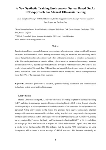
conducted by a participant pool consisting of 3 qualified/experienced and 3 unqualified MUT inspectorson representative industry standard test pieces (flat steel blocks) containing well characterised flaws (flatbottom holes), with locations unknown to the participants. Typical performance variables used in NDTsuch as PoD, coverage, inspection efficiency were taken for each system. The trial results based on theperformance variable indicate that the proposed STE system demonstrates an encouraging results inwhich the unqualified and inexperienced personnel achieved standard competency in a short period.2. The architecture of the proposed STE SystemThe flow diagram of the STE system is shown in figure 2 The system allows the trainee to stepthrough the procedure by pressing on-screen buttons while following the instructions on the screen. Thisacts as a substitute for the long and complicated inspection manuals currently in practice. The STEprocedures can be described as follow,Figure 2. Flow diagram showing the concept of STE system.STEP 1: Load informationThe trainee is able to load information about the test piece and its corresponding ultrasonic datafrom a library of scenarios. These data can either be pre-collected using existing UT equipmentor produced by simulation. The entire matrix of ultrasonic amplitude signals at all locations willbe loaded.STEP 2: Setting InformationThe settings window will be shown on the screen to simulate probe calibration procedure.STEP 3: Manual inspectionTrainee begins the inspection; the STE system will be able to track the movement of the probeposition in a pre-defined reference frame. The A-scan and the C-scan are simultaneouslydisplayed on the screen in real time to guide the trainee. The option of saving the trainee’s datais also made available.4
STEP 4: Performance scoreThe performance score (i.e. PoD, coverage and inspection efficiency) can be generated after thecompletion of the manual inspection.Test pieces are pivotal for evaluating NDT techniques, assessing NDT inspectors or conducting largetrials. In the ideal training environment, a large number of operators can inspect the same test piececontaining simple and complex defects either simultaneously or consecutively. This also allowsstatistically valid results to be obtained and conclusions to be drawn from the significant amount of datathat can be collected. There is already a need for a shared database of real test pieces between researchers,NDT training schools and industries [13]. Real specimens can be difficult to obtain or manufacture. Theymay also be hazardous or too large for practical storage. On the other hand, virtual test pieces can offera real alternative. They are easy to store, transfer and maintain the security of the information theycontain. It is worth mentioning that the library of test scenarios depends to some extent on the acquisitionof data from real specimens for which the true conditions must be determined. In the event where realspecimens are unavailable, instructors or test specialists are able to develop new virtual test pieces bymodifying or combining the raw data from several test pieces already in existence. The signal can beartificially modified for operator practice or testing purposes by simply changing certain characteristicsof the signal, such as the amplitude or signal-to-noise ratio.3. Implementation of the STE SystemThere are basically 2 sources of information available, (i) the two translational data obtained fromthe optical sensor and (ii) the ultrasonic data obtain by the ultrasonic probe, figure 3. In terms of theposition, two degrees of freedom can then be achieved in a pre-defined body frame. The main objectivein the interfacing section is to build an integrated system to obtain data from each of the individual sensorand manipulate it to achieve a meaningful representation for the MUT trainee. A data acquisition systemis required to establish a bidirectional communication between different sensors and the STE operatingsystem.To implement the acquisition system, Arduino Bluetooth module is selected. Translational data areacquired from the sensor denoted byandposition () which can be read directly to the STE system via the ultrasonicand the ultrasonic data (and the ultrasonic data denoted withdevice’s Dynamic-Link Library (DLL) provided by the manufacturer.5. This yields the
Figure 3. Data communication flow for the STE system.3.1 Dead-reckoning spatial positioning systemAn optical sensor has been investigated to determine its suitability as an element for a deadreckoningspatial position module for the STE system. In term of the optical sensing based odometer, designs havebeen reported employing the principles of time-of-flight [17], interferometry [18] and triangulation [19].Owing to its common usage, this technique could possibly be well received since many are alreadyfamiliar with its use. The demands of computer usage have grown increasingly over the years and thishas led to improvements in the optical sensor particularly in delivering the higher tracking speed, betterresponse and reliability required. Optical mouse is also immune to the problems of wear and dirtaccumulation. Optical mice rarely need cleaning, track precisely up to sub-micron accuracy [20] andwork on nearly all surfaces including curved surfaces (large radius) and soft fabric. Combining opticalapproaches with advances in signal/image processing, solid state electronics and wirelesscommunication technologies, it is possible to achieve a small, cordless, high performance andinexpensive optical odometer.Typically an optical mouse module consists of a single light source such as Light-Emitting Diode (LED)o
on the influence of human factors affecting the Probability of Detection (PoD) [1-4]. Moreover, a salary survey conducted by Personnel for Quality and Non-destructive Testing (PQNDT) in 2013 revealed that the average age for an NDT technician is 46 years old. This is an increase of 3.5 years since 2006 when a similar survey has taken place [5]. This indicates that the existing NDT workforce has an aging