Transcription
Electronic Supplementary Material (ESI) for Chemical CommunicationsThis journal is The Royal Society of Chemistry 2012Electronic Supporting Information for:Regioselective placement of alkanethiolate domains on tetrahedral andoctahedral gold nanocrystalsYifeng Wang,a Offer Zeiri,a Louisa Meshi,b,c Francesco Stellaccid and Ira A Weinstock*,a,caDepartment of Chemistry, Ben Gurion University of the Negev, Beer Sheva, 84105, Israel. dDepartment ofMaterials Engineering, Ben Gurion University of the Negev, Beer Sheva, 84105, Israel. cIlse Katz Institute forNanoscale Science & Technology, Ben Gurion University of the Negev, Beer Sheva, 84105, Israel. dInstitute ofMaterials, École Polytechnique Fédérale de Lausanne (EPFL), Lausanne, Switzerland and Department ofMaterials Science and Engineering, Massachusetts Institute of Technology, Cambridge, MA, 02139E-mail: iraw@bgu.ac.ilContents1. Experimental section1.1. Materials.1.2 Instrumentation.1.3 Preparation of 1-protected gold nanoparticles.1.4. Reaction of MPA with 1-protected gold nanoparticles.2. Characterization of the gold nanocrystals (tetra- and octa- and poly-hedral)Figure S1. TEM images of the gold nanocrystals.Figure S2. TEM analysis of the morphology of a tetrahedral nanocrystal.Figure S3. TEM analysis of the morphology of an octahedral nanocrystal.Figure S4. Distribution of diameter/edge length of the gold nanocrystals.Table S1. Summary of the TEM analysis results.Figure S5. HRTEM images the tetrahedral and octahedral gold nanocrystals.Figure S6. HRTEM images of the polycrystalline polyhedral gold nanocrystals.3. Regioselective placement of MP on Au NCs surfacesFigure S7. Regioselective assembly of alkanethiolate domains on Au nanocrystals in water.4. Island-growth of MP domains on near-spherical Au NPsFigure S8. Cryo-TEM images of 1-protected near-spherical Au NPs.Figure S9. Cryo-TEM images of 1-protected near-spherical Au NPs, after addition of MPAcorresponding to 20% of the titration endpoint.5. Island growth of MP domainsFigure S10. Cryo-TEM images of 1-protected Au NPs, after addition of MPA corresponding to 50%of the titration endpoint.S1
Electronic Supplementary Material (ESI) for Chemical CommunicationsThis journal is The Royal Society of Chemistry 20126. Regioselective placement of 11-MU on Au NCs surfacesFigure S11. UV-vis titration of 1-protected Au NCs using 11-MU (1.0 mM).Figure S12. Cryo-TEM images of 1-protected Au NPs, after addition of 11-MU corresponding to20% of the titration endpoint.7. References1. Experimental section1.1 Materialsα-K9AlW11O39 (K91) was synthesized according to the literature method.1, 2 HAuCl4 (99.9 %),NaBH4, 3-mercaptopropanoic acid (MPA), and 11-mercaptoundecnoic acid (MUA, 99%) werepurchased from Sigma-Aldrich. All solutions were prepared using highly purified water (MilliporeDirect-Q), added salts or buffers were of the highest purity available, and all glassware used for thesynthesis and storage of gold-nanoparticle solutions was pretreated with fresh aqua regia (3:1 v/v ratioof HCl to HNO3).1.2 InstrumentationUV-vis spectra were obtained using a Agilent 8453 spectrophotometer at 25 ºC. Transmissionelectron microscopy (TEM) and cryo-TEM images were captured using a FEI Tecnai 12 G2 instrument(120 kV). Grid preparation for TEM (and cryo-TEM) was as previously described.3, 41.3 Preparation of 1-protected Au NPsAu NPs were prepared following a method analogous to that used previously.5 K91 (30 mg) wasdissolved in 10 mL of water. To another 10 mL of water, 76 µL of HAuCl4 (0.131M) was added;afterwards fresh KOH (0.175 M) was added to adjust the pH from 2.17 to ca. 6.4.5 Then, both solutionswere mixed in an ice-bath for 15 min. With vigorous stirring, 0.4 mL of ice-cold fresh NaBH4 (0.1 M)was added dropwise. The solution turned to dark red, indicating the formation of Au NPs. The solutionwas stirred in the ice-bath for an additional 1.5 h. The final pH of the solution was ca. 8.1.4 Reactions of 1-protected gold nanoparticles with MPA and MUAHS(CH2)2CO2H (MPA) was dissolved in pure water prior to use. The UV-vis titration procedure wasas described previously.6 For this, aliquots of the thiol-ligand solutions (5-10 µL of 0.5 or 1.0 mMsolutions) were added sequentially to a spectrophotometer cell (path length 1 cm) that contained 2 mLof the 1-protected Au NPs. The temperature was maintained at 25.0 0.1 C throughout using thePeltier temperature controller.The added MPA was in its acid form, and was in the µM range, while the pH of the Au NPs was nearneutral. Therefore, upon mixing of MPA the Au NPs, it was neutralized to 3-mercaptopropanoate, MP.Because of the low solubility of 11-mercaptoundecnoic acid in water, 2 equivalents of NaOH wasadded to completely dissolve 11-mercaptoundecnoic acid (1.0 mM) and convert it to its salt form,HS(CH2)10CO2– (11-MU).Because the final added mercaptocarboxylate concentrations were in the µM range, the added H (inMPA solutions) or OH- (in the 11-MU solutions) did not noticeably change pH of the solutions.S2
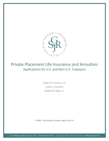
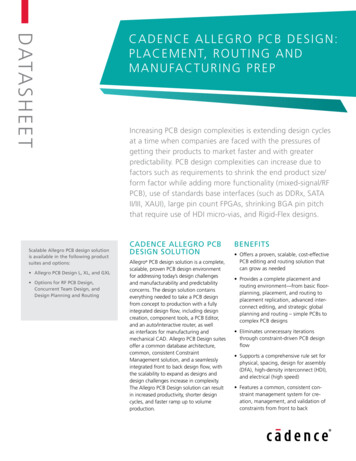
Electronic Supplementary Material (ESI) for Chemical CommunicationsThis journal is The Royal Society of Chemistry 20122. Characterization of the Au NPsFigure S1. TEM images of the Au nanoparticles. Scale bar 20 nm. The obtained nanoparticle solutioncontained a mixture of polyhedral gold particles. These were reacted with MP to give partial displamentof the POM-ligand shells from all the particles, and an average of 20% coverage of the gold surfaces byMP. To our knowledge, no method is yet available for obtaining high yields of uniformly small ( 10nm) tetra- and octa-hedral gold nanocrystals in water.The 2-dimensional TEM projection images (below) indicate that the “triangular” particles aretetrahedral nanocrystals, while the square, diamond-shaped, and hexagonal particles are octahedralnanocrystals. To confirm the 3-dimensional nanoparticle morphologies, “tilt” experiments wereperformed on selected areas of the sample using a FEI Tecnai 12 G2 transmission electron microscope(120 kV) with a single-tilt specimen holder. A series of 2D tilt images over a tilt range of ca. 100 (withrespect to the primary electron beam) were recorded. The observed 2D shapes (Figures S2 and S3) arethen compared to the projections of 3D models.Figure S2. TEM morphology analysis for a tetrahedral nanocrystal. The rotation axis is indicated inpanel A. Tilt-angle-dependent 2D projections are shown in panels B-E. Scale bar 5 nm.S3
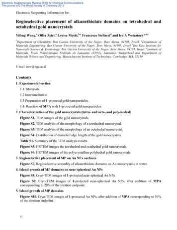
Electronic Supplementary Material (ESI) for Chemical CommunicationsThis journal is The Royal Society of Chemistry 2012Figure S3. TEM morphology analysis for an octahedral nanocrystal. The rotation axis is indicated inpanel A. Tilt-angle dependent 2D projections are shown in panels B-H. Scale bar 5 nm.Frequency 200246810121416Diameter (nm)Figure S4. Distributions of diameter/edge length of the gold nanocrystals.Table S1. Summary of the TEM analysis.ashapenumberpercentagediameter or edge length (nm)polyhedral (ca.spherical)28461%8.2 2.8atriangle5612%8.2 2.4bhexagonal12927%6.7 1.6bDiameter. bEdge length.Figure S5. HRTEM images the tetrahedral and octahedral Au NCs. The insets in panels A and C are thesuggested geometrical shapes. Panels B and D are enlarged images, while insets (upper right in B and D)are fast Fourier transforms of the marked areas in A and C, respectively. Scale bar 5.0 nm. TheFourier transforms are indicative of single crystals.S4
Electronic Supplementary Material (ESI) for Chemical CommunicationsThis journal is The Royal Society of Chemistry 2012Figure S6. HRTEM images of the polyhedral polycrystalline gold nanocrystals. Scale bar 5.0 nm.3. Regioselective placement of MP on Au NCs surfaces (additional images in support of Fig. 5 inthe text).Panels A and B in Figure S7 indicate that MP selectively displaces 1 from the corners and edges ofoctahedral Au NCs. Consistent with this, regioselective placement can also be seen on a polyhedral AuNC which contains a region of high curvature (panel C).Figure S7. Regioselective assembly of alkanethiolate domains on Au nanocrystals in water. Bar 10nm. In all cases, the added amount of MPA was 20% of the endpoint in Figure 4B (see text). Cartoonsare used here to highlight features observed in the cryo-TEM images. Molecules of 1 are indicated usingblue balls, while MP is shown using space-filling notation.In the cryo-TEM images, the particles adopt various orientations relative to the “z” direction of theelectron beam. Due to phase-contrast imaging, vertical regions with considerable depth (at least severalnanometers in the “z” direction) are observed simultaneously. Hence, contrast arising from the POMmonolayer actually represents several POMs above one another (even if not aligned in perfect columns)relative to the electron beam. In the 2D projections obtained by cryo-TEM, one always observes“corners” and “edges”, even though the particles are randomly aligned relative to the “z” direction.The “corners” in the 2D projections arise from edges of the 3D NCs. If POMs are present on theseedges, they will produce columns of POMs (at various angles relative to “z”), observable at differentorientations of the particles. Hence, the absence of intensity from the POMs on the apparent “corners” inthe 2D projections means that POMs are absent from the corresponding edges of the actual NCs.S5
Electronic Supplementary Material (ESI) for Chemical CommunicationsThis journal is The Royal Society of Chemistry 2012The “edges” in the 2D projections arise from differently oriented faces of the 3D NCs. To observePOMs on the apparent “edges” of these 2D projections, numerous POMs must lie on the faces of theNCs themselves.The particle in panel C has a few larger faces that create a region of higher curvature. In 2Dprojection, no POMs are observed on this more highly curved region. However, many POMs areobserved at the remaining peripheral regions of the approximately spherical particle. We have observedthis on numerous particles, and it provides additional support for the selective displacement of POMs atthe much more acute intersections of faces present in tetrahedral or octahedral NCs.4. Island-growth of MP domains on near-spherical Au NPsOur previous study demonstrated that on highly faceted, approximately spherical 14-nm Au NPs,mercaptocarboxylates displace POMs via an associative mechanism, and the organic domains expandrapidly over the gold surface by “island” growth.6The present Au colloidal solution contains ca. 61% of near-spherical (polyhedral) Au NPs with anaverage diameter of 8.2 nm. The cryo-TEM images in Figure S8 indicate that these Au NPs wereprotected with monolayers of 1 in aqueous solutions.Figure S8. Cryo-TEM images of 1-protected near-spherical Au NPs. Bar 10 nm.Partial displacement of the POM ligands on the near-spherical Au NPs by MP leads to the formationof alkanethiolate domains in the ligand shell. This was assessed by reacting an amount of MPAcorresponding to 20% of the endpoint in Figure 4B (see text) with the 1-protected Au NC solution. Afterreaction, regions of the POM “ring” are missing as shown by the cryo-TEM images (Figure S9). These“empty” areas are now occupied by MP which is not visible in the visual field of the transmissionelectron microscope (TEM). This observation is consistent with the island-growth mechanism.6Figure S9. Cryo-TEM images of 1-protected near-spherical Au NPs, after addition of MPAcorresponding to the 20% of the endpoint in Figure 4B. Bar 10 nm.S6
Electronic Supplementary Material (ESI) for Chemical CommunicationsThis journal is The Royal Society of Chemistry 20125. Island growth of MP domains (50% MPA)Figure S10. Cryo-TEM images of 1-protected Au NPs, after addition of MPA corresponding to the50% of the endpoint in Figure 4B.As can be seen from the cryo-TEM images as well as the cartoon illustrations, MP moleculesaggregate into domains on the surfaces of octahedral, tetrahedral Au NCs. On the approximatelyspherical particles (panels G and H), domains of the thiolate ligands are observed, consistent with theisland-growth mechanism.6 Comparing to the images in Fig. 5 (text), and Fig. S7 and S9, all of whichcontain MPA at 20% of its endpoint concentration, the regions occupied by MP become larger.Notably, however, POMs are now removed from the faces, as well as from the edges. Different degreesof POM displacement are observed due to random orientations of the NCs.S7
Electronic Supplementary Material (ESI) for Chemical CommunicationsThis journal is The Royal Society of Chemistry 20126. Regioselective placement of MU on Au NCs surfacesFigure S11. UV-vis titration of 1-protected Au NCs using 11-MU (1.0 mM). An endpoint is observed atca. 15.1 µM, close to the (14.9 µM) value for the MPA endpoint in Figure 4B.Figure S12. Cryo-TEM images of 1-protected Au NPs, after addition of 11-MU corresponding to the20% of the endpoint in Figure S11. In panel A, it is possible that 1 has not been entirely displaced fromthe edge of the octahedral NC seen in the 2D image as the highly curved region at the bottom of theparticle.The results in Figure S12 indicated that other alkanethiolates like 11-MU, also selectively replacemolecules of 1 at the edges of the octahedral and the tetrahedral Au NCs.7. References1. J. J. Cowan, A. J. Bailey, R. A. Heintz, B. T. Do, K. I. Hardcastle, C. L. Hill and I. A. Weinstock,Inorg. Chem., 2001, 40, 6666-6675.2. J. J. Cowan, C. L. Hill, R. S. Reiner and I. A. Weinstock, in Inorg. Synth., ed. D. Coucouvanis, JohnWiley & Sons, Inc., New York, 2002, vol. 33, pp. 18-23.3. A. Neyman, L. Meshi, L. Zeiri and I. A. Weinstock, J. Am. Chem. Soc., 2008, 130, 16480-16481.4. Y. Wang, A. Neyman, E. Arkhangelsky, V. Gitis, L. Meshi and I. A. Weinstock, J. Am. Chem. Soc.,2009, 131, 17412-17422.5. Y. Wang, O. Zeiri, V. Gitis, A. Neyman and I. A. Weinstock, Inorg. Chim. Acta, 2010, 363, 44164420.6. Y. Wang, O. Zeiri, A. Neyman, F. Stellacci and I. A. Weinstock, ACS Nano, 2012, 6, 629-640.S8
octahedral gold nanocrystals Yifeng Wang,a Offer Zeiri,a Louisa Meshi,b,c Francesco Stellaccid and Ira A Weinstock*,a,c a Department of Chemistry, Ben Gurion University of the Negev, Beer Sheva, 84105, Israel. dDepartment of Materials Engineering, Ben Gurion University of the Negev, Beer Sheva, 84105, Israel. cIlse Katz Institute for