Transcription
Product ManualVIKINGEN397-3a 1999
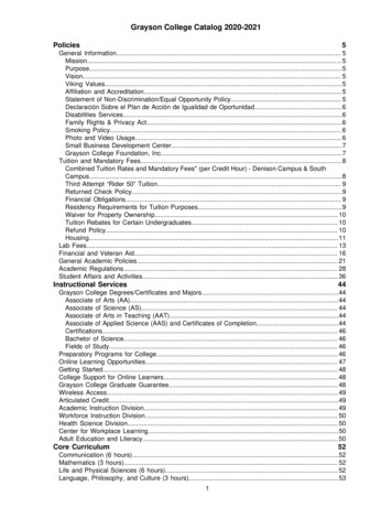
One partner all over the worldHägglunds DrivesOriginal EN397-2, 1998is one of the worlds leadingmanufacturerof heavy dutyhydraulic drivesystems. Ifwhat you needWorldwide distribution and service organizationis low speed andhigh torque, thenHägglunds Drivesshould be your partner.If what you need is a durabledrive system that will work underthe toughest conditions with a minimumof maintenance, then Hägglunds Drives should be your partner. We develop, manufacture &market complete drive-systems and components of the highest quality, based upon our uniqueradial piston motors. Our industrial and marine customers are to be found all over the world.They know that when they need solutions, support or service, they have in us a partner theycan trust. Hägglunds Drives main office and manufacturing plant is situated in Mellansel,Sweden. In Addition Hägglunds Drives is represented in 40 countries worldwide.The content in this manual is subject to change without notice or obligation, unlesscertified referring to a certain purchase order. Information contained herein shouldbe confirmed before placing orders.2
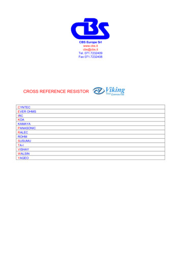
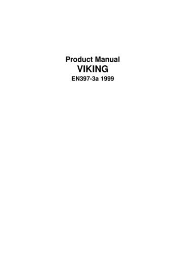
FeaturesHigh torquesLow speedsThe Viking motor is a high-torque low speed motor,which can be mounted directly on a winch drum orto a shaft without intermediate gears. This presentsmany practical benefits which appeal to the users ofthe equipment.Smooth, low speed performance from zero to ratedspeed without the need of reductiongears and nocompromise on output torque.Variable speed controlThe Viking can drive and brake in both directionswith variable speed by smoothly controlling the flowof oil in the circuit.SafetyFor cranes and hoists Viking motors and brakeassemblies are DNV approved. You don t need totake risks.Severe environmentsThe Viking motor is designed to be highly resistantto severe working conditions and environments. TheViking has proven itself on board ships, in underwaterapplications, in explosive and chemically corrosiveindustrial environments, in extreme heat and freezingcold.High efficiencyThe mechanical efficiency as well as the startingefficiency is 97%. Because of the extremely lowmoment of inertia the motor is virtually insensitive toshock loads, and protects the driven equipment.Viking is still the best tension control motor available.Quick selection diagram for Viking motorsThe diagram below represents the torque and speed, for winch applications.Oil viscosity in the motor case 40 cSt (187 SSU).TorquekNmTorquelbf·ft x 103Speed rpmFor continuous duty and/or operation in line screened area, please contact your Hägglunds Drivesrepresentative for final selection.3
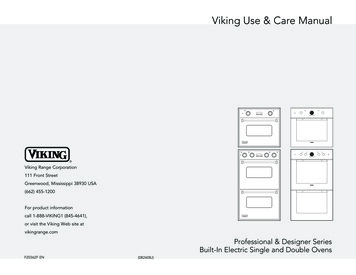
Functional descriptionThe Viking motors are radial piston type with rotating case. The case is supported on the stationary cylinderblock (5) by two main bearings. An even number of radially positioned pistons (3) work in cylinder bores inthe cylinder block, which also houses the inlet andoutlet ports (A and C). Each piston is coupled by a1piston rod (2) to a cross head pin (6) upon whichfour cam rollers (7) are mounted. The two inner cam5rollers press against the cam ring (8) while the twoouter rollers work within their respective guide plates(1). The cam ring is anchored to the rotating case.The distributor (4) directs the input oil to the pistonsduring their work strokes andreturns the exhaustedoil back to the tank. The distributor is coupled to therotating case via a safety coupling (9). The motorcan be connected to a driven machine via twomounting surfaces on the rear end of the motor. The7symmetrical design of the motor has made it possibleto construct it as a 2-speed motor. This means that8two different speeds are obtained for a given flow.The simplest way of performing displacement change over is byconnecting a special valve, known as a 2-speed valve, direct to the connecting flange on the cylinder block.The motor is designed so that pressure pulsations in the motor case are avoided. This has the advantagethat impurities are not sucked into the case.Fig. 1 Viking motor1. Guide plate5. Cylinder block4. DistributorA Port A9. Safety couplingC Port C3. Piston2. Piston rod7. Cam rollers6. Cross head pin8. Cam ring4
Calculation fundamentalsFor more informationSee Powerful Engineering(EN347-4).QuantitySymbolMetricPowerP kWOutput torqueT NmSpecific torqueTs Nm/barRotational speedn rpmRequired pressurep barDefinitionsRated speed1)Rated speed is the highest allowedspeed for a charge pressure of 12 bar(175 psi) above case pressure. Whena closed loop system is used, a minimum of 15% of oil is to be exchangedin the main loop.1)Operating above rated conditions requiresengineering approval.Max speedMaximum speed is the maximumallowed speed. Special considerations are necessary regarding chargepressure, cooling and choice ofhydraulic system for speeds ratedabove.Accepted conditions for standardtype of motor:1. Oil viscosity 20 - 40 - 10000 cSt(98 - 187 - 4650 SSU). See page 23.2. Temperature -35 C to 70 C(-31 F to 158 F).3. Case pressure 0-3 bar (0-45 psi)Pressure peaks and at standstill 8 bar(116 psi)4. Charge pressure (see diagram).5. Volumetric losses (see diagram).UShplbf·ftlbf·ft/1000 psirpmpsiQuantitySymbol MetricPressure loss pl barCharge pressurepc barFlow rate requiredq l/minTotal volumetric loss ql l/minDisplacementVi cm3/revMechanical efficiency ηm 0,97USpsipsigpmgpmin3/revDataF U L L D IS P L AC E M E N TD IS P L AC E M E N T S H IF TM a x . ***p re s s u reD isp la ce m entS pe cificto rq ue **R a te dsp e e d*M a x.sp e e dViTsnnp4 4 -0 3 3 0 03325531002003201662261002001 :24 4 -0 4 7 0 04710751002003202356371002001 :24 4 -0 6 8 0 0679010890170320339354901701 :24 4 -0 9 2 0 0924014780145320461874801451 :26 4 -1 1 1 0 01 1 0 8017670120320554288701201 :26 4 -1 3 5 0 01 3 4 99215601102506750107601101 :26 4 -1 6 3 0 01 6 3 40260501002508171130501001 :28 4 -1 4 8 0 01 4 8 402365590320-----8 4 -1 7 9 0 01 7 9 612865585320-----8 4 -2 1 3 0 02 1 3 753405580320-----8 4 -2 5 1 0 02 5 0 903995575320-----8 4 -3 8 0 0 03 8 0 006054060250-----8 4 -2 2 3 0 02 2 3 0035555553201 1 1 5017760851 :28 4 -3 3 8 0 03 3 7 8053835352501 6 8 8926950701 :28 4 -2 5 1 0 02 5 0 903994055250836213345751 :38 4 -3 8 0 0 03 8 0 0060525352501 2 6 6720235601 :38 4 -2 5 1 0 02 5 0 9039940552501 6 7 2426645752 :38 4 -3 8 0 0 03 8 0 0060525352502 5 3 3440335602 :3R a tioM o to rty p eD isp la ce m entS pe cificto rq ue **R a te dsp e e d*M ax.sp e e dViTsnnF U L L D IS P L AC E M E N TR a tioD IS P L AC E M E N T S H IF TM a x . ***p re s s u reD isp la ce m entS pe cificto rq ue **R a te dsp e e d*M a x.sp e e dD isp la ce m entS pe cificto rq ue **R a te dsp e e d*ViTsnnpM ax.sp e e dViTsnn4 4 -0 3 3 0 020326951002004 4 -0 4 7 0 0287381410020046501011347100200465014419071002004 4 -0 6 8 0 04145492901 :217046502072746901701 :24 4 -0 9 2 0 056474756 4 -1 1 1 0 067689718014546502823738801451 :27012046503384485701206 4 -1 3 5 0 08231 :21 0 9 356011036004115467601106 4 -1 6 3 0 01 :29971 3 2 275010036004996613501001 :28 4 -1 4 8 0 09061 2 0 1755904650-----8 4 -1 7 9 0 010961 4 5 4655854650-----8 4 -2 1 3 0 013041 7 2 9255804650-----8 4 -2 5 1 0 015312 0 3 0655754650-----8 4 -3 8 0 0 023203 0 7 5640603600-----8 4 -2 2 3 0 013611 8 0 4855554650680902460851 :28 4 -3 3 8 0 020612 7 3 393535360010311 3 6 6950701 :28 4 -2 5 1 0 015312 0 3 0640553600510676945751 :38 4 -3 8 0 0 023193 0 7 56253536007731 0 2 5235601 :38 4 -2 5 1 0 015312 0 3 064055360010211 3 5 3745752 :38 4 -3 8 0 0 023193 0 7 562535360015462 0 5 0435602 :3M o to rty p e*1 :2Related to a required charge pressure of 12 bar (175 psi) for motors in braking mode. Special considerations regarding charge pressure,cooling and choice of hydraulic system for speeds above rated.** Theoretical value*** The motors are designed according to DNV-rules. Test pressure 70 bar/1000 psi. Peak/transient pressure 70 bar/1000 psi maximum,allowed to occur 10000 times.5
Ordering codesIn order to identify Hägglunds Drives equipment exactly, the following ordering code is used. Theseordering codes should be stated in full in all correspondence e.g. when ordering spare parts.Viking motorsTorque armBand brakeBrake cylinderBrake bracket6
Ordering codesIn order to identify Hägglunds Drives equipment exactly, the following ordering code is used. Theseordering codes should be stated in full in all correspondence e.g. when ordering spare parts.Valve V46-CValve V46-ORear bracketSpeed encoderFlange adapterMounting set for Speed encoderFeatureAdvantageBenefitsRadial pistonSmall axial lengthCompact - low weightMultiple stroke designLarge displacement - direct driveConstant displacementHigh torque/inertia-ratioLow speed - low noise levelFull torque in all positionsQuick reversing capacityEven number of pistons Main bearings unloadedHigh external load capacityGuide plate designTransverse piston force avoidedHigh mechanical efficiencyReduced piston/cylinder wearFull starting torqueSuperior low speed performanceCam & guide plateroller bearingsStick-slip eliminatedHigh mechanical efficiencySuperior low speed performanceFull starting torqueRotating caseNon-rotating pistonsBrake surface machinedMachined spigotsFree wheeling capabilityBandbrake availableDirect mounting to winch drum7
Dimensions44/64-seriesFig. 2Fig. 3Fig. 4DFEBCNMainConn.KLGAIJDrainConn.H84-seriesFig. 5Fig. 6Fig. 7DFEBCDrainConn.AGG MK LJMainConn.JIHTable 1 Dimensions for the 3/4"676320(26,61) (12,59)66,5346,5560198,5(2,61) (13,64) (22,05) (7,81)24xM2024xM24955440620(37,59) (17,32) (24,41)56264(2,19) (10,39)766390(30,16) ries274(10,78)50(1,96)--45 84-series--200(7,87)115(4,52)90 -1*: Pilot port Y2*: Pilot port XTable 1a Key & 2-speed adapter dimensionsPMmm(in)260149(10,24) (5,87)64858790430-series (33,78) (31,10) (16,93)OLmm(in)Jholes51257(2,00) (10,12)αHmm(in)Iholes44770700360438-series (30,31) (27,56) (14,17) (17,24)4508411001020530 (17,72)-series (43,31) (40,16) (20,87)Gmm(in)520(1150)BSP BSP1 1/4" in Drainkgconn. conn.(lb)
DimensionsTorque armFig. 9 Torque arm TAC-1250-BFig. 10 Torque arm TAC-1000-KBBCCDDAAEGGEFFTorquearmAmm (in)BCmm (in) mm (in)Dmm (in)EholesFmm (in)Gmm (in)Weightkg 40(1,57)155(342)Torque armFig. 11 Mounting of pivoted attachmentx 2 mm (0,079) misalignment in installation.x 15 mm (0,59) movement when in use.TAC-1000-KFor 44-series34000*65000**65000TAC-1000-KFor 52000152000182000Torque armAlternativepositionSteel:SS 2134-01DIN St E39BS 4360 Grade 50 CMax. torqueMax. torque Max. torque(Nm)(Nm)(Nm)For alternatingFor pulsating At staticdirection oftorquetorquetorqueMax. torqueMax. torque Max. torque(lbf·ft)(lbf·ft)(lbf·ft)For alternatingFor pulsating At staticdirection oftorquetorquetorqueTAC-1000-KFor 44-series25000*48000**48000TAC-1000-KFor 12000112000134000*Exceeding this value result in greater wear onkeys and keyways.** Do not exceed MB for motor cover, see page 21.Note: Ideal angle α 0 9
DimensionsBracketsRearbracketRope drumMotorCoverFront bracketBracketFor motorBA-43single acting44-seriesBA-43double acting44-seriesBA-63single acting64-seriesA mm (in)B mm (in)C mm sBA-85single anddouble acting84-seriesRBC-46rear bracketRBC-84rear bracketE mm (in)208(8,19)871(34,29)BA-63double actingD mm (in)F mm (in)G mm (in)Attachment mm (in)Weight kg (lbs)ø28 (1,102)4 1,65)1188(46,77)1160(45,67)-ø28 (1,102)11 ,57)190(7,48)80(3,15)540(21,26)-ø28 (1,102)4 30(9,05)100(3,94)710(27,95)-ø35 (1,38)4 holes107(236)Fig. 12 BA-43 and BA-63, single actingFig. 13 BA-43 and BA-63, double actingBrake adjustmentscrewBrake adjustment screw2xM162xM16AAEBEBCCFDDFGFig. 14 BA-85, single and double actingFig. 15 RBC-46/84 rear bracketBrake adjustment screw20x 28(1,10)CAEBBEFFD10D
AccessoriesWinch valve for open systems, type V46-OWinch valve V46-O is designed for open systems together with motors of series 44 and 64, and particularlyfor suspended load applications. It is a counter balance valve, controlled from the low pressure side, combinedwith a displacement shifting function. It also includes crossover relief valves and a special valve for brakeoperation. The valve is mounted directly on the motor.Working pressure: 210-350 bar (3000-5000 psi)Capacity: 800 l/min (211 US. gal/min)Weight: V46-O-1, 110 kg (242 lb) and V46-O-2, 100 kg (220 lb)Fig. 16 Valve V46-O-1, with control blockFig. 17 Valve V46-O-2, without control blockV46-O-1: The valve is delivered with a control block,affording advanced safety and control function for displacement shifting.V46-O-2: The valve is delivered without a control blockand must be supplemented with control function.Winch valve for closed systems, type V46-CWinch valve V46-C is designed for closed systems together with motors of series 44 and 64, and particularlyfor suspended load applications. It is a combined unloading and displacement shifting valve with built-infunctions for pressure limitation and oil exchange, thus eliminating the need for a transmission valve. Thevalve is mounted directly on the motor.Working pressure: 210-350 bar (3000-5000 psi)Capacity: 800 l/min (211 US. gal/min)Weight: V46-C-1, 90 kg (190 lb) and V46-C-2, 80 kg (175 lb)Fig. 18 Valve V46-C-1, with control blockFig. 19 Valve V46-C-2, without control blockV46-C-1: The valve is delivered with a control block,affording advanced safety and control functions. Functionsneeding to be actuated are start, stop and selection ofmotor displacement. This is accomplished by a solenoidvalve (must be ordered separately), which is mounteddirectly on the control block.V46-C-2: The valve is delivered without a control blockand must be supplemented with all directional control andcontrol functions.11
Accessories2-speed valve for 84-seriesThe 84-series motor it is possible, if a two speed valve is selected to set displacement ratios 1:2 and 1:3.The differences between a two-position and three-position valve are only the position of the end cover andthat the "X-port" is plugged.Note: Displacement shifting is not allowed when the motor is running.Fig. 21 Three-position valveFig. 20 Two-position valveThe end cover in this position,and pilot-port "X" pluggedgives a two-position valve.The end cover in this position,and pilot-port "X" pluggedgives a three-position valve.Free wheeling valve for closed and open loop systems, type VFWFree wheeling valve VFW is designed for both closed and open hydraulic systems together with motors ofseries 44, 64 and 84.Working pressure: max 350 bar (5000 psi).Capacity: 800 l/min (211 US. gal/min)Weight: 56 kg (124 lb)Fig. 24 Fitting of valve V46 and valve VFW on motorseries 44/64Fig. 22 Valve VFW, mounted with valve V46The VFW valve is mounted directly on the winch valvetype V46-C or V46-O (44/64-series).Fig. 23 Valve VFW, mounted separatelyThe VFW valve is mounted to the system with hoses.Directional control valve has to be added (84-series).12
AccessoriesBrake bracket, type BB-46 and BB-85Brake assembly, type BA-43, BA-63 and BA-85Each brake is available in three versions depending on their brake direction, clockwise, counter clockwiseand double acting. The Viking band brakes are fatigue resistant for the maximum motor torque in eachmotor series. The brake is intended to be used as a parking brake. For hanging loads in wet environmentswe recommend the use of a protective cover over the band brake. The brake linings are of non-asbestosmaterial and have DNV type approval.Fig. 25 Single acting double band,type BB 46 and BA 43/63Fig. 26 Single acting double band,type BB 85 and BA 85Fig. 27 Double acting, one band in either directiontype BB 46 and BA 43/63Fig. 28 Double acting, one band in either directiontype BB 85 and BA 85Braking torqueBraking torque in braking force direction, frictionfactor µ 0,35 after running-in period.Braking force directionTypeLoad LoadClockwiseCounter ClockwiseDouble acting13Single acting - double bandNmlbf·ftDouble 663006500047900BA-8519500014380012000088500
AccessoriesSpeed encoder with mounting set SMSpeed encoder with mounting set SM mounted on the motor (fig. 30). The Speed encoder could be orderedin 15 different models, full scale output from 2 to 300 rpm.Fig. 29 Speed encoderFig. 30 Speed encoder mounted on the motorParking lock unitParking lock unit for winch and industrial applications e.g. belt conveyor installations. The parking lock canonly be used were there is no demand for dynamic braking. In addition to the locking cylinder with bracket,a ratchet-wheel (with data according to dimension drawing) must be installed on the outer mounting surfaceof the hydraulic motor rear cover.Fig. 32 Winch applicatonFig. 31 Industrial applicatonON - The piston rod withit s head, is pressedagainst the ratchet-wheeldue to spring-force.OFF - The piston rod isreleased from the ratchetwheel by means of oilpressure.Parking lockunitCylinderbarpsiCompletelyopen atpressure in"A"-portbarpsi2,7394,3Begin to openat pressure in"A"-portMax allowedpressure"A"-port and "D"portbarpsi62701000Brake cylinder, type BCI-MDisplacementWeightcm3in3kglb1348,22351Fig. 33 Brake cylinderFor brake assembly BA-43, BA-63 and BA-85. The brakecylinder is the actuator for the Viking brakes. The bandbrake,including brake cylinder, is the fail-safe type. This meansthat the brake comes on due to spring force from a strongspring inside the brakecylinder, if the pressure to the cylinder is released. For good resistance to corrosion, the piston-rod is cromeplated and made of stainless steel.Brake cylindertypeBCI-M-1X-XXXBCI-M-30-XXXBegin to openat pressure in"A"-portMax allowedCompletely openpressureat pressure in"A"-port and 435021,470154
AccessoriesProtective cover, type WP-43, WP-63 and WP-85For applications in open and wet conditions we recommend a cover to be mounted over the bandbrake. Thisis due to some brake efficiency losses in case of water on the lining and braking surface. The covers aremade of 4 mm (0,158 in) glassfibre reinforced plastic, and are to be used with brake bracket BB-46 / BB-85.Fig. 34 WP-43 or WP-63Fig. 35 WP-85Harsh industrial environmentTo protect the main seal when the motor is used in harsh environment, an extra V-ring can be mounted onthe 44- and 64-series motors. When using Hägglunds Drives bracket type BB-46, the guiding diameter isalready machined. 330 1( 13 0,04)BSP 1/4"For lubricationFig. 36 V-ringV-ring9,25 0,25(0,36 0,01)15
Diagrams for VikingViking motorsDiagram 1 Charge pressure - Motor series 44 & 64Valid for 1 bar (14,5 psi) case pressure.With increased case pressure, the chargepressure must be increased accordingly.Case 1: The motor works in braking mode. Required charge pressure at the inlet port is according todiagram above.Case 2: The motor works in driving mode only. Required back pressure at the outlet port corresponds to30% of value given in diagram above, but may not be lower than 2 bar (29 psi).Case 3: The motor is used with 2-speed valve. Required charge pressure at inlet port for valve is accordingto diagrams.Diagram 2 Charge pressure - Motor series 84without 2-speed valve (A & B type)Diagram 3 Charge pressure - Motor series 84with 2-speed valve (A & B type)Valid for 1 bar (14,5 psi) case pressure.With increased case pressure,the charge pressure must beincreased accordingly.Valid for 1 bar (14,5 psi) case pressure.With increased case pressure, the chargepressure must be increased accordingly.rpmrpm16
Diagrams for VikingViking motorsDiagram 4 Pressure loss through motor caseViscosityPressure loss through motor casefrom D1 - D2 (opposite flow directiongives the same pressure loss).Pressure loss represents in equalparts inlet- and outlet flow pressureloss. Viscosity 40 cSt/187 SSU.64-series44-series84-seriesDiagram 5 Pressure loss - Motor series 4440 cSt/187 SSUDiagram 6 Pressure loss - Motor series 6440 cSt/187 SSUFull displacementFull 0064-11100Diagram 7 Pressure loss - Motor series 84, 40 cSt/187 SSU45200Motor series 84-14800, 84-25100and 84-38000 without 2-speed 6100650Motor series 84-25100 and84-38000 with 2-speed valve50084-380001/3 displacement84-251001/3 displacement35030015202001084-38000 Full displacement150584-25100 Full 0506070rpm35500500Motor series 84-33800Motor series 84-2230045030Half displacement45030Half displacement400253002025015p bar350p psip 1040025200150101001005550Full displacement00102030rpm40506050Full displacement00007017102030rpm40506070p psi p bar84-25100p bar16012 p psi18040p psi14
Diagrams for VikingViking motorsDiagram 8 Volumetric loss - Motor series 4440 cSt/187 SSUDiagram 9 Volumetric loss - Motor series 6440 cSt/187 SSUThe diagram shows average valuesThe diagram shows average valuesql B-typeql B-typeql A-typeql D-typeql A-typeql D-typeqC B-typeqC A-typeqC D-typeqC B-typeql Volumetric losses (incl. case drain flow).Diagram 10 Volumetric loss - Motor series 84without 2-speed valve, 40 cSt/187 SSUThe diagram shows average valuesqC A-typeqC D-typeqC Casing drain flow from D port.Diagram 11 Volumetric loss - Motor series 84with 2-speed valve, 40 cSt/187 SSUql B-typeql B-typeThe diagram shows average valuesql A-typeql A-typeqC B-typeqC B-typeql D-typeqC A-typeqC A-typeqC D-typeThe diagrams above shows the average values. When calculating volumetric losses using other viscosities,multiply the value given in the diagram by the factor K.Diagram 12 Factor K - Variation in volumetric lossesViscosity18
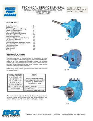
Diagrams for VikingViking motorsDiagram 13 Overall efficiency - Motor type 44-04700(A-distributor), 40 cSt/187 SSU Pc 12 bar (174 psi)kNm2025 kW 50 kWlbf·ft75 kW 100 kW90 %91%1400092 %120001693 %800050 kW 100 kW 150 kWlbf·ft400005090 %4591%6000400043000092 %3593 %3094 %2595 %8kNm55401000094 %12Diagram 14 Overall efficiency - Motor type 64-11100(A-distributor), 40 cSt/187 SSU Pc 12 bar (174 psi)200002095 %15100001020005000020406080100 rpm05101520253035404550556065070 rpmDiagram 15 Overall efficiency - Motor type 84-14800(A-distributor), 40 cSt/187 SSU Pc 12 bar (174 psi)kNm7050 kW 100 kW 150 kWlbf·ft5000090 %91%6092 %400005093 %300004094 %302000095 %20100001000051015202530354045505560 rpmFlushing of motor caseThe Viking motors have very high total efficiency, and they are now frequently used in applications withhigh power. To avoid high temperature in the motor case the heat must be cooled away, becausehigh temperature gives lower viscosity and thatgives reduction in basic rating life.Fig. 37 Flushing connection D1 and D2on motor series 44 & 64- For continuous duty in applications with anambient temperature of 20 C (68 F), themotor case must be flushed when the outputpower exceeds the values shown below.Max power without flushingViking 44/64Viking 84120 kW140 kW(161 hp)(188 hp)19
Examples of installationsFig. 38 Complete Winch driveFig. 40 Motor series 64 mountedin one bracketFig. 39 Motor series 84 shaft mountedwith torque armFig. 42 Motor series 64 with V46 valve and brake bracketFig. 41 Motor series 44mounted in two bracketsFig. 43 Motor series 44/64with brake bracketFig. 44 Motor series 84 withbrake bracket20
Calculation of external loads for VikingFig. 45 Motor series 44 & 64Fig. 46 Motor series 84Fig. 47 Shaft mounted motor with torque armMb Fr · aFig. 48 Torque armMb F r · aFig. 49 Motor mounted in one bracketT Fr · lminLmin T · aMba 350 mm (13,8 in) - 44 seriesa 362 mm (14,3 in) - 64 seriesa 390 mm (15,4 in) - 84 seriesFig. 50 Motor mounted in two bracketsMb F r · aMa l 1 · FFig. 51 Winch installationFr F ·l2l1 l2Mb Fr · aRl 21F·la lFr F
Max permitted external static and dynamic loads for VikingIf the torque Mb exceeds the values in the table below,static or dynamic, the outer flange must be used. Incase of higher axial forces Fa than listed in the table,please contact your nearest Hägglunds Drivesrepresentative for consultation.MotorseriesTorque, MbDiagram 16 Motor series 44Max. Axial force, 0044808440000294806000013440Diagram 17 Motor series 64Diagram 18 Motor series 8422
Choice of hydraulic fluidThe Hägglunds Drives hydraulic motors are primarily designed to operate on conventional petroleum basedhydraulic oils. The hydraulic oil can be chosen in consultation with the oil supplier or your local sales office,bearing the following requirements in mind:GeneralThe oil shall have FZG (90) fail stage minimum 11 described in IP 334 (DIN 51354). The oil must alsocontain inhibitors to prevent oxidation, corrosion and foaming. The viscosity of mineral oil is highly dependentof the temperature. The final choice of oil must depend on the operating temperature that can be expectedor that has been established in the system and not in the hydraulic tank. High temperatures in the systemgreatly reduce the service life of oil and rubber seals, as well as resulting in low viscosity, which in turnprovides poor lubrication. Content of water shall be less than 0,1%. In Industrial applications with highdemands for service life, the content of water shall be less than 0,05%.Temperature limitsRecommended viscosityAt operating temperature: 40-150 cSt/187-720 SSU.Normal operating temperature should be lessthan 50 C (122 F)Viscosity limits 100 recommended 150* for operationwith large temperaturedifferenceViscosity indexMin. permitted in continuous dutyMin. permitted in intermittent dutyMax. permitted40 cSt/187 SSU20 cSt/98 SSU**10000 cSt/48000 SSU* Many hydraulic fluids with VI-improvers are subject to temperaryand permanent reductions of the viscosity.** Low viscosity gives reduced basic rating life for the motorsand reduction of max allowed power.Nitrile seals (std motor)Viton sealsSilicone seals-35 C to 70 C-20 C to 100 C-60 C to 70 CNitrile seals (std motor)Viton sealsSilicone seals-31 F to 158 F-4 F to 212 F-76 F to 158 FFire resistant fluidThe following fluids are tested for Hägglunds Drives motors (ISO/DP 6071).FluidApprovedSealsInternal paintHFA: Oil (3-5%) in water emulsionNo--HFB: Inverted emulsion 40-45% water in oilYesNitrile (std motor)Not painted*HFC: Water-glycolYesNitrile (std motor)Not painted*HFD:R - Phosphate estersYesVitonNot painted*HFD:S - Chlorinated hydrocarbonsYesVitonNot painted*HFD:T - Mixture of the aboveYesVitonNot painted*HFD:U - Other compositionsYesVitonNot painted*HFD synthetic fluidsEnvironmentally acceptable fluidsFluidApprovedSealsInternal paintVegetable */**Fluid HTGYesNitrile(std motor)-Synthetic **Esters HEYesNitrile(std motor)-*Vegetable fluids give good lubrication and small change of viscosity with different temperature.Vegetable fluids must be controlled every 3 months and temperature shall be less than 45 C(113 F) to give good service life for the fluid.**Environmentally acceptable fluid give the same servicelife for the drives, as mineral oil.23
Choice of hydraulic fluidDown rating of pressure data and basic rating lifeDown rating of pressure, for motors used in systemswith fire resistant fluids, the maximum pressure formotor given on data sheet must be multiplied withfollowing factors:HFA-fluidnot fit for useHFB-fluid0,7 x maximum pressure for motorHFC-fluid0,7 x maximum pressure for motorHFD-fluid0,9 x maximum pressure for motorDown rating of basic rating life, for motors used insystems with fire resistant fluids, the "expected basicrated life" must be multiplied with following factors:HFA-fluidHFB-fluidHFC-fluidHFD-fluidnot fit for use0,26 x expected life with mineral oil0,24 x expected life with mineral oil0,80 x expected life with mineral oilFiltrationThe oil in a hydraulic system must always be filtered and also new oil from your supplier has to be filteredwhen adding it to the system. The grade of filtration in a hydraulic system is a question of service life v.s.money spent on filtration.In order to obtain stated service life it is important to follow our recommendations concerning contaminationlevel.When choosing the filter it is important to consider the amount of dirt particles that the filter can absorb andstill operate satisfactory. For that reason we recommend a filter with an indicator that gives a signal when itis time to change the filter cartridge.Filtering recommendationsBefore start-up, check that the system is thoroughly cleaned.1. In general the contamination level in our motors should not exceed ISO 4406 19/15 (NAS 10).2. For heavy-duty applications the contamination level should not exceed ISO 4406 16/13 (NAS 7).3. When filling the tank and motor case, we recommend the use of a filter with the grade of filtration β10 75.Explanation of "Grade of Filtration"Grade of filtration β10 75 indicates the following:β10 means the size of particle 10µm that will be removed by filtration. 75 means the grade of filtration of above mentioned size of particle. The grade of filtration is defined asnumber of particles in the oil before filtration in relation to number of particles in the oil after filtration.Ex. Grade of filtration is β10 75.Before the filtration the oil contains N number of particles 10µm and after p
Quick selection diagram for Viking motors The diagram below represents the torque and speed, for winch applications. Oil viscosity in the motor case 40 cSt (187 SSU). High torques The Viking motor is a high-torque low speed motor, which can be mounted directly on a winch drum or to a shaft without intermediate gears. This presents