Transcription
NXP SemiconductorsUser's GuideFRDM-K32L2B3 Freedom BoardDocument identifier: FRDMK32L2B3UGRev. 0, 04/2020
NXP SemiconductorsContentsChapter 1 Overview. 3Chapter 2 FRDM-K32L2B3 features.4Chapter 3 Get to know the FRDM-K32L2B3.5Chapter 4 References .6Chapter 5 Hardware description. 7Chapter 6 FRDM-K32L2B3 jumper options and headers. 10Chapter 7 Known issue.11Chapter 8 Useful links.12User's GuideFRDM-K32L2B3 Freedom Board, Rev. 0, 04/20202 / 13
NXP SemiconductorsChapter 1OverviewThe FRDM-K32L2B3 Freedom board is designed to work in a stand-alone mode or as the main board of the Arduino boards.The FRDM-K32L2B3 is a modular development platform that enables rapid prototyping and tool reuse through reconfigurablehardware.User's GuideFRDM-K32L2B3 Freedom Board, Rev. 0, 04/20203 / 13
NXP SemiconductorsChapter 2FRDM-K32L2B3 featuresThe FRDM-K32L2B3 supports the following features: MK32L2B31VLH0A MCU (Arm Cortex -M0 core, 48-MHz clock, up to 256 KB of Flash, 32 KB of RAM, 64LQFPpackage) I/O headers for easy access to MCU I/O pins Compatible with Arduino boards On-board debug circuit: MK20DX128VFM5 (OpenSDA) with a virtual serial port NXP inertial sensor FXOS8700CQ Reset button and two user buttons 2 user LEDs Four-digit segment LCD module Dual-role USB interface with a micro USB connectorUser's GuideFRDM-K32L2B3 Freedom Board, Rev. 0, 04/20204 / 13
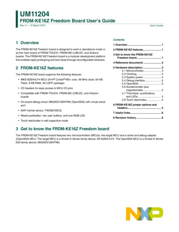
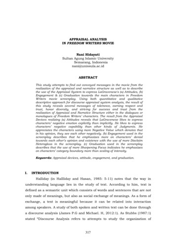
NXP SemiconductorsChapter 3Get to know the FRDM-K32L2B3Figure 1. FRDM-K32L2B3 top sideThe FRDM-K32L2B3 features two MCUs: the target MCU and the serial and debug adapter (OpenSDA) MCU. The target MCUis a K32 L series family device (K32L2B31VLH0A). The OpenSDA MCU is a Kinetis K series K20 family device(MK20DX128VFM5).User's GuideFRDM-K32L2B3 Freedom Board, Rev. 0, 04/20205 / 13
NXP SemiconductorsChapter 4ReferencesThe documents listed below should be referenced for more information on the K32 L series, Freedom System, and MCU modules.These can be found in the documentation section at www.nxp.com/FRDM-K32L2B3. FRDM-K32L2B3-SCH (schematics) K32L2B3xRM (reference manual) Software packageUser's GuideFRDM-K32L2B3 Freedom Board, Rev. 0, 04/20206 / 13
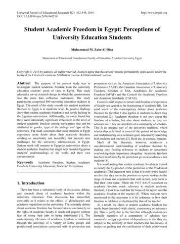
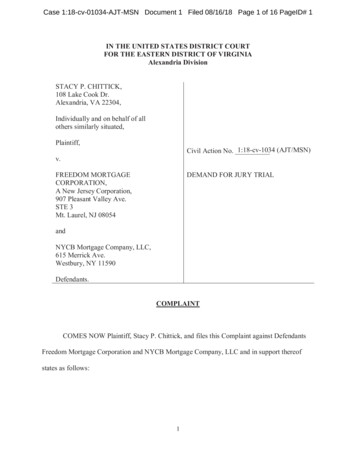
NXP SemiconductorsChapter 5Hardware descriptionFRDM-K32L2B3 is a Freedom MCU module featuring the K32L2B3—a K32 L Series MCU in a 64 LQFP package. An on-boardOpenSDA debug circuit provides the Serial Wire Debug (SWD) interface and a power supply input through a single micro-USBconnector. The block diagram of the FRDM-K32L2B3 board is shown in Figure 2.Figure 2. Block diagram of FRDM-K32L2B35.1 MCUFRDM-K32L2B3 features the K32L2B31VLH0A MCU. This 48-MHz MCU is a part of the K32 L family and it is implemented in a64 LQFP package. The features of the K32L2B31VLH0A MCU are as follows: 32-bit Arm Cortex-M0 core, 48 MHz Memories— Up to 256 KB of flash— 32 KB of SRAM Clocks— Clock generation module with a High-frequency Internal Reference Clock (HIRC) of 48 MHz and two Low-frequencyInternal Reference Clocks (LIRC) of 2 MHz and 8 MHz for the system and CPU clock generation— System oscillator supporting external crystals or resonators— Low-power 1-KHz RC oscillator for the RTC and COP watchdog Analog peripherals— 16-bit SAR ADC w/ DMA supportUser's GuideFRDM-K32L2B3 Freedom Board, Rev. 0, 04/20207 / 13
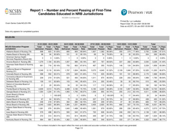
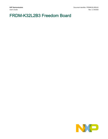
NXP SemiconductorsHardware description— 12-bit DAC w/ DMA support— Two high-speed analog comparators (CMP) with internal 6-bit Digital-to-Analog Converters (DAC)— VREF 1.2 V voltage reference Connectivity and communications interfaces— Two 8-bit Serial Peripheral Interfaces (SPI)— USB FS device controller— USB voltage regulator— Two I2C modules— Two low-power UART modules (LPUART)— UART with an ISO7816 module— FlexIO module (with 8 pins/4 shifters/4 timers implemented) Timers— 6-channel Timer/PWM module— Two 2-channel Timer/PWM modules— 2-channel Periodic Interrupt Timer (PIT)— Real-Time Clock (RTC)— Low-Power Timer (LPT)— System tick timer Human-Machine Interface (HMI)— Segment LCD controller—the maximum segment is 8 x 28/4 x 32— General-purpose input/output controller clockingThe K32 L series MCU starts up from the internal 48-MHz HIRC by default. The software can enable the main external oscillator(EXTAL/XTAL) if desired. The external oscillator ranges from 4 MHz to 40 MHz. The 8-MHz oscillator is the default externalsource for the system and RTC clocks (respectively) on the FRDM-K32L2B3 board.5.2 System powerFRDM-K32L2B3 is compatible with DC 5 V and 3.3 V power supplies, because the K32L2B3 MCU can work at voltages from1.71 V to 3.6 V.The main power source for the FRDM-K32L2B3 module is derived from the OpenSDA USB micro-B connector (J13). One lowdropout regulator provides a 3.3-V supply from the 5-V input voltage. Refer to the "POWER" page of the FRDM-K32L2B3schematics for more details. The OpenSDA MK20DX128VFM5 is always powered by 3.3 V.5.3 Debug interfaceThere are two debug interfaces provided: the on-board OpenSDA circuit and the external Arm Cortex SWD connector (J11). TheARM Cortex SWD connector is a standard 10-pin connector that provides an external debugger cable access to the SWD interfaceof the K32L2B31VLH0A. Alternatively, the on-board OpenSDA debug interface can be used to access the debug interface of theK32L2B31VLH0A.5.4 OpenSDAThe on-board MK20DX128VFM5-based OpenSDA circuit provides a SWD debug interface to the K32L2B31VLH0A. A standardUSB A male to micro-B male cable can be used for debugging via the USB connector (J13). The OpenSDA interface also providesa USB-to-serial bridge. The drivers for the OpenSDA interface are at the official NXP website. These drivers and more utilitiesUser's GuideFRDM-K32L2B3 Freedom Board, Rev. 0, 04/20208 / 13
NXP SemiconductorsHardware descriptionare at ugadapter:OPENSDA.Figure 3. OpenSDA block diagram5.5 Accelerometer and magnetometerThe FXOS8700CQ 6-axis digital sensor accelerometer and magnetometer is connected to the K32L2B31VLH0A MCU throughan the I2C interface (I2C0) and GPIO/IRQ signals (PTE24 and PTE25).5.6 Pushbuttons, visible light sensor, and LEDsFRDM- K32L2B3 also features: Two push-button switches: SW1-PTA4 and SW3-PTC3 Visible light sensor connected to the ADC input signals (ADC0 SE3/PTE22) Two LEDsUser's GuideFRDM-K32L2B3 Freedom Board, Rev. 0, 04/20209 / 13
NXP SemiconductorsChapter 6FRDM-K32L2B3 jumper options and headersFRDM-K32L2B3 jumper options and headers shows all jumper options on the FRDM-K32L2B3. The default installed jumpersettings are indicated by in bold.Table 1. FRDM-K32L2B3 jumper optionsOptionJumperSettingDescriptionK32L2 SWD CLKJ18ONConnect J11 4 toK32L2 SWD CLKOFFDisconnect J11 4 toK32L2 SWD CLKONConnect VDD toVDD K32L2B3OFFAllow current measurementon MCU VDDONConnect VDD K32L2 toP3V3 K32L2OFFDisconnect VDD K32L2 toP3V3 K32L2ONConnect visible light sensorto PTE22OFFDisconnect visible lightsensor to PTE22ONConnect SW3 to PTC3OFFDisconnect SW3 to PTC3ONConnect VREGIN toP5V K32L2OFFDisconnect VREGIN toP5V K32L2ONConnect P3V3 SDA toP3V3 VREGOFFDisconnect P3V3 SDA toP3V3 VREGMCU VDD currentmeasurementVDD K32L2Visible light sensorSW3VREGINP3V3 SDAUser's GuideJ17J20J8J21J7J9FRDM-K32L2B3 Freedom Board, Rev. 0, 04/202010 / 13
NXP SemiconductorsChapter 7Known issueIn the SCH-46355 Rev A version, C1 is not DNP. Because there is only a weak internal pull-up resistor on the NMI pin (SW1), itmay cause an unexpected NMI interrupt at powerup if the NMI is enabled, or boot a ROM entry (if it is enabled). Removingcapacitor C1 prevents this. If a filter is required, an external pull-up resistor of 4.7 k and a capacitor of 100 pF are suggested. InRev A1, capacitor C1 is DNP.User's GuideFRDM-K32L2B3 Freedom Board, Rev. 0, 04/202011 / 13
NXP SemiconductorsChapter 8Useful links www.nxp.com www.iar.com/NXP www.segger.com— www.segger.com/jlink-flash-download.htmlUser's GuideFRDM-K32L2B3 Freedom Board, Rev. 0, 04/202012 / 13
How To Reach UsHome Page:nxp.comInformation in this document is provided solely to enable system and software implementers touse NXP products. There are no express or implied copyright licenses granted hereunder todesign or fabricate any integrated circuits based on the information in this document. NXPreserves the right to make changes without further notice to any products herein.Web Support:NXP makes no warranty, representation, or guarantee regarding the suitability of its products fornxp.com/supportany particular purpose, nor does NXP assume any liability arising out of the application or useof any product or circuit, and specifically disclaims any and all liability, including without limitationconsequential or incidental damages. “Typical” parameters that may be provided in NXP datasheets and/or specifications can and do vary in different applications, and actual performancemay vary over time. All operating parameters, including “typicals,” must be validated for eachcustomer application by customer's technical experts. NXP does not convey any license underits patent rights nor the rights of others. NXP sells products pursuant to standard terms andconditions of sale, which can be found at the following address: nxp.com/SalesTermsandConditions.While NXP has implemented advanced security features, all products may be subject tounidentified vulnerabilities. Customers are responsible for the design and operation of theirapplications and products to reduce the effect of these vulnerabilities on customer’s applicationsand products, and NXP accepts no liability for any vulnerability that is discovered. Customersshould implement appropriate design and operating safeguards to minimize the risks associatedwith their applications and products.NXP, the NXP logo, NXP SECURE CONNECTIONS FOR A SMARTER WORLD, COOLFLUX,EMBRACE, GREENCHIP, HITAG, ICODE, JCOP, LIFE VIBES, MIFARE, MIFARE CLASSIC,MIFARE DESFire, MIFARE PLUS, MIFARE FLEX, MANTIS, MIFARE ULTRALIGHT,MIFARE4MOBILE, MIGLO, NTAG, ROADLINK, SMARTLX, SMARTMX, STARPLUG, TOPFET,TRENCHMOS, UCODE, Freescale, the Freescale logo, AltiVec, CodeWarrior, ColdFire,ColdFire , the Energy Efficient Solutions logo, Kinetis, Layerscape, MagniV, mobileGT, PEG,PowerQUICC, Processor Expert, QorIQ, QorIQ Qonverge, SafeAssure, the SafeAssure logo,StarCore, Symphony, VortiQa, Vybrid, Airfast, BeeKit, BeeStack, CoreNet, Flexis, MXC, Platformin a Package, QUICC Engine, Tower, TurboLink, EdgeScale, EdgeLock, eIQ, and Immersive3Dare trademarks of NXP B.V. All other product or service names are the property of their respectiveowners. AMBA, Arm, Arm7, Arm7TDMI, Arm9, Arm11, Artisan, big.LITTLE, Cordio, CoreLink,CoreSight, Cortex, DesignStart, DynamIQ, Jazelle, Keil, Mali, Mbed, Mbed Enabled, NEON,POP, RealView, SecurCore, Socrates, Thumb, TrustZone, ULINK, ULINK2, ULINK-ME, ULINKPLUS, ULINKpro, µVision, Versatile are trademarks or registered trademarks of Arm Limited (orits subsidiaries) in the US and/or elsewhere. The related technology may be protected by any orall of patents, copyrights, designs and trade secrets. All rights reserved. Oracle and Java areregistered trademarks of Oracle and/or its affiliates. The Power Architecture and Power.org wordmarks and the Power and Power.org logos and related marks are trademarks and service markslicensed by Power.org. NXP B.V. 2020.All rights reserved.For more information, please visit: http://www.nxp.comFor sales office addresses, please send an email to: salesaddresses@nxp.comDate of release: 04/2020Document identifier: FRDMK32L2B3UG
applications and products to reduce the effect of these vulnerabilities on customer's applications and products, and NXP accepts no liability for any vulnerability that is discovered. Customers should implement appropriate design and operating safeguards to minimize the risks associated with their applications and products.