Transcription
UM11204FRDM-KE16Z Freedom Board User's GuideRev. 0 — 12 March 20191 OverviewThe FRDM-KE16Z Freedom board is designed to work in standalone mode oras the main board of FRDM-TOUCH, FRDM-MC-LVBLDC, and Arduinoboards. The FRDM-KE16Z Freedom board is a modular development platformthat enables rapid prototyping and tool reuse through reconfigurable hardware.2 FRDM-KE16Z featuresThe FRDM-KE16Z board supports the following features. MKE16Z64VLF4 MCU (Arm Cortex -M0 core, 48 MHz clock, 64 KBFlash, 8 KB RAM, 48 LQFP package) I/O headers for easy access to MCU I/O pins Compatible with FRDM-TOUCH, FRDM-MC-LVBLDC, and Arduinoboards On-board debug circuit: MK20DX128VFM5 (OpenSDA) with virtual serialport NXP inertial sensor, FXOS8700CQ Reset pushbutton, two user buttons, and one RGB LED Touch electrodes in self-capacitive modeUser's GuideContents1 Overview.12 FRDM-KE16Z features. 13 Get to know the FRDM-KE16ZFreedom board. 14 Reference documents . 25 Hardware description. 35.1 Microcontroller. 35.2 Clocking. 45.3 System power. 45.4 Debug interface.55.5 OpenSDA.55.6 Accelerometer plusmagnetometer. 55.7 Thermistor, pushbuttons,and LEDs. 55.8 Touch electrodes.56 FRDM-KE16Z jumper options andheaders. 57 Useful links.68 Revision history. 63 Get to know the FRDM-KE16Z Freedom boardThe FRDM-KE16Z Freedom board features two microcontrollers (MCUs): the target MCU and a serial and debug adapter(OpenSDA) MCU. The target MCU is a Kinetis E Series family device, KE16Z64VLF4. The OpenSDA MCU is a Kinetis K SeriesK20 family device, MK20DX128VFM5.Downloaded from Arrow.com.
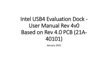
NXP SemiconductorsReference documentsFigure 1. FRDM-KE16Z top side4 Reference documentsFor more information on the Kinetis E Series, Freedom System, and MCU modules, see the following document. The documentsare listed in the documentation section of www.nxp.com/FRDM-KE16Z. FRDM-KE16ZSCH (schematics) KE1xZP48M48SF0RM (reference manual) SDK 2.5.0 FRDM-KE16ZFRDM-KE16Z Freedom Board User's Guide, Rev. 0, 12 March 2019User's GuideDownloaded from Arrow.com.2/7
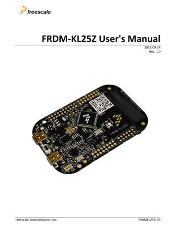
NXP SemiconductorsHardware description5 Hardware descriptionThe FRDM-KE16Z Freedom board is a Freedom MCU Module featuring the KE16Z, a Kinetis E Series microcontroller in a 48LQFP package. An onboard OpenSDA debug circuit provides a Serial Wire Debug (SWD) interface and a power supply inputthrough a single micro-USB connector.Figure 2. on page 3 shows the block diagram of the FRDM-KE16Z Freedom board.Figure 2. Block Diagram of FRDM-KE16Z5.1 MicrocontrollerThe FRDM-KE16Z features the KE16Z64VLF4 MCU. This 48 MHz microcontroller is part of the Kinetis KE family and isimplemented in a 64 LQFP package.The features of the KE16Z64VLF4 MCU are: 32-bit Arm Cortex-M0 core, 48 MHz Memories— 64 KB flash— 8 KB SRAM Clocks— Clock generation module with FLL for system and core clock generation— 48 MHz high accuracy fast internal reference clock (FIRC)FRDM-KE16Z Freedom Board User's Guide, Rev. 0, 12 March 2019User's GuideDownloaded from Arrow.com.3/7
NXP SemiconductorsHardware description— 8 MHz/2 MHz high accuracy slow internal reference clock (SIRC)— 4-40 MHz fast external oscillator (OSC)— 128 KHz low-power oscillator (LPO)— Low-power FLL (LPFLL) Analog peripherals— 1 x 12-bit SAR ADC with up to 16 channels input per module— 1 x high-speed analog comparators (CMP) with internal 8-bit digital to analog converter (DAC) Connectivity and communications interfaces— 1 x low-power serial peripheral interface (LPSPI)— 1 x low-power inter-integrated circuit (LPI2C) module— 3 x low-power universal asynchronous receiver/transmitter (LPUART) modules— 1 x CAN module (MSCAN), with 5 receive buffers and 3 transmit buffers Timers— 2 x FlexTimer (FTM) modules— 1 x 16-bit low-power timer(LPTMR) with flexible wake-up control— 1 x 32-bit Periodic Interrupt Timer(LPIT)— 1 x Programmable Delay Block(PDB) with flexible trigger system— Real-time clock (RTC) Human-machine interface (HMI)— Supports up to 32 interrupt request (IRQ) sources— Up to 42 GPIO pins with interrupt functionality— 25-channel touch sensing interface(TSI), supporting both self-capacitive and mutual-capacitive mode5.2 ClockingKinetis E Series MCU startup from internal 48 MHz FIRC by default. Software can enable the main external oscillator (EXTAL/XTAL) if desired. The external oscillator can range from 4 MHz to 40 MHz. An 8 MHz oscillator is the default external source forsystem clock and real-time clock respectively on the FRDM-KE16Z board.5.3 System powerThe FRDM-KE16Z is compatible with DC 5 V and 3.3 V power supply, as KE16Z can work from 2.7 V to 5.5 V.The main power source for the FRDM-KE16Z module is derived from the OpenSDA USB micro-B connector (J6). One low-dropoutregulator provides 3.3 V supply from the 5.0 V input voltage. All of the user-selectable options can be configured headers J18,J19. For more information, see the POWER page of the FRDM-KE16Z schematics. Since, KE16Z64VLF4 MCU supports 2.7 Vto 5.5 V power supply, MCU KE16Z can be 3.3 V powered by setting J19 2-3 connected, and 5 V powered by setting J19 1-2connected. However, OpenSDA MK20DX128VFM5 is always 3.3 V powered.FRDM-KE16Z Freedom Board User's Guide, Rev. 0, 12 March 2019User's GuideDownloaded from Arrow.com.4/7
NXP SemiconductorsFRDM-KE16Z jumper options and headers5.4 Debug interfaceThere are two debug interface options provided: the onboard OpenSDA circuit and an external Arm Cortex SWD connector (J14).The Arm Cortex SWD connector is a standard 10-pin connector that provides an external debugger cable access to the SWDinterface of the KE16Z64VLF4. Alternatively, the onboard OpenSDA debug interface can be used to access the debug interfaceof the KE16Z64VLF4.5.5 OpenSDAAn onboard MK20DX128VFM5-based OpenSDA circuit provides an SWD debug interface to KE16Z64VLF4. A standard USB Amale to micro-B male cable is used for debugging via the USB connector (J6). The OpenSDA interface also provides a USB toserial bridge. Drivers for the OpenSDA interface are provided in the P&E Micro OpenSDA Freedom Toolkit. These drivers andmore utilities can be found online at http://www.pemicro.com/opensda .5.6 Accelerometer plus magnetometerAn FXOS8700CQ 6-axis digital sensor accelerometer plus magnetometer is connected to the KE16Z64VLF4 MCU through anI2C interface (LPI2C0) and GPIO/IRQ signals (PTA3 and PTA2).5.7 Thermistor, pushbuttons, and LEDsThe FRDM- KE16Z board also features: Thermistor connected to ADC input signals (ADC0 SE2/ADC0 SE3) Two pushbutton switches: SW2-PTD3, SW3-PTD2 RGB LED5.8 Touch electrodesThe FRDM-KE16Z board features two touch electrodes to demonstrate TSI functions in self-capacitive mode.The touch electrode 1 is connected to TSI channel 0, and touch electrode 2 is connected to TSI channel 1.The FRDM-KE16Z also outputs TSI signals to IO header J2 and J4 to support FRDM-TOUCH board, which demonstrates fourtouch keys in a mutual-capacitive mode, touch slider, and rotary.6 FRDM-KE16Z jumper options and headersThe following is a list of all of the jumper options on the FRDM- KE16Z. The default installed jumper settings are indicated in bold.FRDM-KE16Z Freedom Board User's Guide, Rev. 0, 12 March 2019User's GuideDownloaded from Arrow.com.5/7
NXP SemiconductorsUseful linksTable 1. FRDM-KE16Z jumper optionsOptionJumperPower supplySettingDescription1-2KE16Z64VLF4 MCU is 5 Vpowered2-3KE16Z64VLF4 MCU is 3.3 VpoweredONConnect VDD to VDD KE16ZOFFAllow current measurement onMCU VDD1-2Reset from pushbutton SW12-3Bypass push buttonONConnect MCU SWD DIO toOpenSDAOFFDisconnect MCU SWD DIO toOpenSDAONConnect MCU SWD CLK toOpenSDAOFFDisconnect MCU SWD CLKto OpenSDAJ19MCU VDD currentmeasurementJ18Reset selectionJ5MCU SWD DIO signalJ8MCU SWD CLK signalJ97 Useful links www.NXP.com— NXP.com/Kinetis www.iar.com/NXP www.pemicro.com— http://www.pemicro.com/opensda www.segger.com— http://www.segger.com/jlink-flash-download.html8 Revision historyTable 2. Revision history on page 6 summarizes the changes since the initial release.Table 2. Revision historyRevision numberDateSubstantial changes003/2019Initial releaseFRDM-KE16Z Freedom Board User's Guide, Rev. 0, 12 March 2019User's GuideDownloaded from Arrow.com.6/7
How To Reach UsHome Page:nxp.comInformation in this document is provided solely to enable system and software implementers touse NXP products. There are no express or implied copyright licenses granted hereunder todesign or fabricate any integrated circuits based on the information in this document. NXPreserves the right to make changes without further notice to any products herein.Web Support:NXP makes no warranty, representation, or guarantee regarding the suitability of its products fornxp.com/supportany particular purpose, nor does NXP assume any liability arising out of the application or useof any product or circuit, and specifically disclaims any and all liability, including without limitationconsequential or incidental damages. “Typical” parameters that may be provided in NXP datasheets and/or specifications can and do vary in different applications, and actual performancemay vary over time. All operating parameters, including “typicals,” must be validated for eachcustomer application by customer's technical experts. NXP does not convey any license underits patent rights nor the rights of others. NXP sells products pursuant to standard terms andconditions of sale, which can be found at the following address: nxp.com/SalesTermsandConditions.While NXP has implemented advanced security features, all products may be subject tounidentified vulnerabilities. Customers are responsible for the design and operation of theirapplications and products to reduce the effect of these vulnerabilities on customer’s applicationsand products, and NXP accepts no liability for any vulnerability that is discovered. Customersshould implement appropriate design and operating safeguards to minimize the risks associatedwith their applications and products.NXP, the NXP logo, NXP SECURE CONNECTIONS FOR A SMARTER WORLD, COOLFLUX,EMBRACE, GREENCHIP, HITAG, I2C BUS, ICODE, JCOP, LIFE VIBES, MIFARE, MIFARECLASSIC, MIFARE DESFire, MIFARE PLUS, MIFARE FLEX, MANTIS, MIFARE ULTRALIGHT,MIFARE4MOBILE, MIGLO, NTAG, ROADLINK, SMARTLX, SMARTMX, STARPLUG, TOPFET,TRENCHMOS, UCODE, Freescale, the Freescale logo, AltiVec, C‑5, CodeTEST, CodeWarrior,ColdFire, ColdFire , C‑Ware, the Energy Efficient Solutions logo, Kinetis, Layerscape, MagniV,mobileGT, PEG, PowerQUICC, Processor Expert, QorIQ, QorIQ Qonverge, Ready Play,SafeAssure, the SafeAssure logo, StarCore, Symphony, VortiQa, Vybrid, Airfast, BeeKit,BeeStack, CoreNet, Flexis, MXC, Platform in a Package, QUICC Engine, SMARTMOS, Tower,TurboLink, and UMEMS are trademarks of NXP B.V. All other product or service names are theproperty of their respective owners. AMBA, Arm, Arm7, Arm7TDMI, Arm9, Arm11, Artisan,big.LITTLE, Cordio, CoreLink, CoreSight, Cortex, DesignStart, DynamIQ, Jazelle, Keil, Mali,Mbed, Mbed Enabled, NEON, POP, RealView, SecurCore, Socrates, Thumb, TrustZone, ULINK,ULINK2, ULINK-ME, ULINK-PLUS, ULINKpro, µVision, Versatile are trademarks or registeredtrademarks of Arm Limited (or its subsidiaries) in the US and/or elsewhere. The relatedtechnology may be protected by any or all of patents, copyrights, designs and trade secrets. Allrights reserved. Oracle and Java are registered trademarks of Oracle and/or its affiliates. ThePower Architecture and Power.org word marks and the Power and Power.org logos and relatedmarks are trademarks and service marks licensed by Power.org. NXP B.V. 2019.All rights reserved.For more information, please visit: http://www.nxp.comFor sales office addresses, please send an email to: salesaddresses@nxp.comDate of release: 12 March 2019Document identifier: UM11204Downloaded from Arrow.com.
I/O headers for easy access to MCU I/O pins Compatible with FRDM-TOUCH, FRDM-MC-LVBLDC, and Arduino boards On-board debug circuit: MK20DX128VFM5 (OpenSDA) with virtual serial port NXP inertial sensor, FXOS8700CQ Reset pushbutton, two user buttons, and one RGB LED Touch electrodes in self-capacitive mode