Transcription
PRELIMINARYWTS701WINBOND SINGLE-CHIP TEXT-TO-SPEECH PROCESSORThe information contained in this datasheet may be subject to change withoutnotice. It is the responsibility of the customer to check the Winbond USA website(www.winbond-usa.com) periodically for the latest version of this document, andany Errata Sheets that may be generated between datasheet revisions.-1-Publication Release Date May 2003Revision 3.09
WTS7011. GENERAL DESCRIPTIONThe WTS701 is a high quality, fully integrated, single-chip Text-to-Speech solution that is ideal for usein applications such as automotive appliances, GPS/navigation systems, cellular phones and otherportable products or accessories. The WTS701 product accepts ASCII (Unicode and Big5 forMandarin) input via a SPI port and converts it to spoken audio via an analog output or digital CODECoutput.The WTS701 integrates a text processor, smoothing filter and multi-level memory storage array on asingle-chip. Text-to-speech conversion is achieved by processing the incoming text into a phoneticrepresentation that is then mapped to a corpus of naturally spoken word parts. The synthesisalgorithm attempts to use the largest possible word unit in the appropriate context to maximize naturalsounding speech quality. The speech units are stored uncompressed in a multi-level, non-volatileanalog storage array to provide the highest sound quality to density trade-off. This unique, single-chipsolution is made possible through Winbond’s patented multilevel storage technology. Voice and audiosignals are stored directly into solid-state memory in their natural, uncompressed form, providingsuperior quality voice reproduction.The chip can be programmed through the SPI port, allowing downloading of different languages andspeaker databases when made available by Winbond.-2-
WTS7012. FEATURES Fully Integrated SolutionSingle-chip compact text-to-speech translationNo algorithm development requiredSelectable digital and analog audio outputSimple SPI interfaceReprogrammable solution enables loading different voice or language Text-To-Speech Algorithm CharacteristicsHigh quality speech synthesis using speech element concatenationWinbond’s standard 100-year speech retentionAudio stored as uncompressed analog waveform – industry’s highest quality and most natural sounding Easy to Use and ControlReal time conversion for streaming textGeneral text preprocessing and normalizationUser customization for special characters such as SMS icons and chat emoticonsUser customization for application specific abbreviations Language SupportSupport U.S. English and Mandarin (Beijing dialect)Other languages in development or in planning Device ManagementAccepts ASCII, Unicode or Big5 streaming text256-byte text bufferPlayback of Phonetic AlphabetVariable speed playbackControl of pitch changeSupports Power Down mode.Supports Pause and Resume, Stop and Finish text conversion commandsEmbedded characters support to control speed, volume, case sensitivity, and silent behavior Peripheral Control16-bit linear PCM slave interface output supportSPI serial port for control commands and status report to system’s host controllerHardware handshake control signalsAnalog audio output with 8Ω speaker driver, digital volume control and line level o/pAnalog audio input (AUXIN) for driving external audio to the speaker Low Power Consumption 2.7 to 3.3V (VCC) Supply VoltageOperating Current:ICC Convert 35 mA (typical)Standby Current:ISB 1µA (typical) Device CharacteristicsAvailable in 56-lead TSOP packageIndustrial temperature range (-40C to 85C)3V/5V logic tolerance-3-Publication Release Date: May 2003Revision 3.09
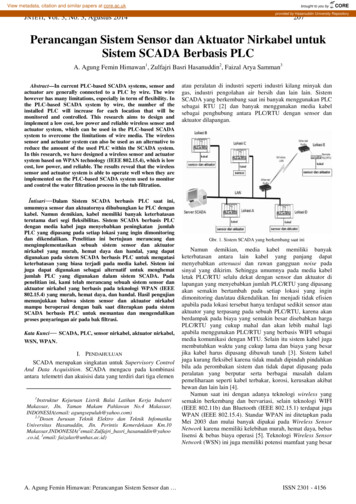
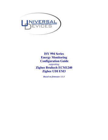
WTS7013. BLOCK DIAGRAM3.1. WTS701 BLOCK DIAGRAMCS\SS\MOSIMISOSCLKR/B\INT\SPI INTERFACERESETMLS 1CLOCKXTAL2GENERATIONRAMHIGH VOLTAGEMLSGENERATIONPHOENEMEAUXOUTAMPMEMORYAUX OUTREFERENCEGENERATIONSpkr.AMPSP SP-ANALOG SIGNALAUXINAUXCONDITIONINGAMP13 BIT CODECLINEAR/ 2’S COMPLEMENTPower ConditioningVCCAVSSAVSSAVSSDVSSDVCCDVCCDATT CAPFigure 1. WTS701 Block Diagram.-4-VFSVDXVCLK
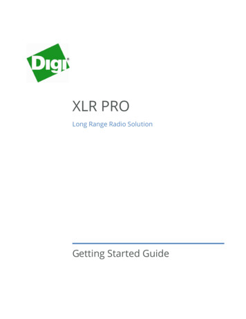
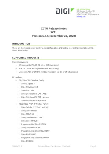
WTS7013.2. WTS701 TYPICAL APPLICATIONSBasebandProcessorWTS701HOST UTVFSVCLKVDXAUXOUTAUXINSP SP-Figure 2. WTS701 Configuration for Digital (CODEC) Environment.WTS701HOST UTAUXINLine outLine inSP SP-Figure 3. WTS701 Configuration for Analog Environment-5-Publication Release Date: May 2003Revision 3.09
WTS7014. TABLE OF CONTENTS1. GENERAL DESCRIPTION. 22. FEATURES . 33. BLOCK DIAGRAM . 43.1. WTS701 Block Diagram . 43.2. WTS701 Typical Applications. 54. TABLE OF CONTENTS . 65. PIN CONFIGURATION . 86. PIN DESCRIPTION . 97. FUNCTIONAL DESCRIPTION. 117.1 Text-To-Speech Mechanism . 127.1.1 Text Normalization . 127.1.2 Words-to-Phoneme conversion . 127.1.3 Phoneme Mapping . 127.2 Physical Interface . 137.2.1 Clocking Requirements. 137.2.2 Power Down Mode. 147.2.3 Power and Grounding . 147.2.4 SPI Interface . 157.2.5 Flow Control Interface . 167.2.6 The CODEC Interface . 167.2.7 The Analog Interface. 177.2.8 Resetting . 187.3 Communication Protocol. 197.3.1 Command Classes. 207.3.2 Status Register. 217.3.3 Interrupt Handler . 227.3.4 BCNT -- Byte Count Register. 237.3.5 Command Acceptance. 237.3.6 Data Acceptance. 237.4 Commands Overview . 237.4.1 Command Description . 267.4.2 Illegal Commands . 377.4.3 Configuration Registers . 377.4.4 System Operation . 417.4.5 Initialization and Configuration. 43-6-
WTS7017.4.6 Converting Text. 437.5 SPI Interface . 467.5.1 SPI Transactions. 467.6 CODEC Interface. 497.7 Control Characters. 527.7.1 Phonetic Alphabet Playback . 527.7.2 Speed Change . 547.7.3 Volume Change . 557.7.4 Case Sensitivity. 557.7.5. Pause Control . 557.8 Customizing Abbreviations . 567.8.1 Abbreviation Data Format . 567.8.2 Abbreviation Table Format. 577.8.3 Command Execution. 577.9 Device Programming . 587.10 Text-To-Speech Processor Commmands – Quick Reference Table. 597.10.1 Text Input Format. 647.10.2. Buffer length limit . 657.10.3. Undefined characters. 658. TIMING WAVEFORMS . 668.1 SPI Timing Diagram. 668.2 CODEC Timing Diagrams . 689. ABSOLUTE MAXIMUM RATINGS. 7010. ELECTRICAL CHARACTERISTICS . 7111. TYPICAL APPLICATION CIRCUIT . 7412. PACKAGE DRAWING AND DIMENSIONS . 7513. ORDERING INFORMATION. 7614. VERSION HISTORY . 77-7-Publication Release Date: May 2003Revision 3.09
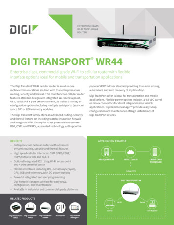
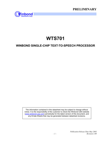
WTS7015. PIN CONFIGURATIONThe following sections detail the pins of the WTS701 processor.Table 1 shows all the pins and the signals that use them in different configurations. It also shows thetype and direction of each signal. Figure 4 shows the physical pin out of the 56-pin TSOP package.NC156NCVS S A255NCVC LK354AUXOUTVF S453NCVDX552AUXINM IS O651NCXT AL2750NCXT AL1849NCVS S D948VC C AVS S D101047NCVC C D1146SP VC C D1245NCINT \1344VS S AM OS I1443NCSS\1542SP-S C LK1641NCNC1740AT T C APNC1839NCNC1938NCNC2037NCNC2136VS S ANC2235NCNC2334NCNC2433NCCS\2532NCR /B \2631NCR ES ET2730NCNC2829NCW TS701Figure 4. 56-pin TSOP Package Connection Diagram.-8-
WTS7016. PIN DESCRIPTIONTable 1. WTS701 Pin Signal Assignment.PIN NO.SYMBOLI/OFUNCTION2,36,44VSSAGAnalog Ground pins.3VCLKI4VFSICODEC master clockCODEC frame synchronization signal5VDXOCODEC data output. This pin puts data out in the linear PCMunsigned or 2’s complement format. It is tri-stated until the userrequests a CONVERT operation.6MISOOSPI Master In, Slave Out pin. Serial data line used tocommunicate with SPI master. Pin is tri-state when SS 1.7XTAL2OCRYSTAL 2: This is the crystal oscillator output. It is theinversion of XTAL1.8XTAL1ICRYSTAL 1: This is the crystal oscillator input. This pin may bedriven by an external clock. The clock to the WTS701 processoris configured by a clock configuration register, which is set by thehost processor during the initialization phase.9,10VSSDGDigital Ground pin.11,12VCCDPPositive Digital Voltage Supply pin. These pins carry noisegenerated by internal clocks in the chip. They must beindependently bypassed to Digital Ground to ensure correctdevice operation and not connected together.13INTOInterrupt Output; an open drain output that indicates that thedevice wishes an interrupt service. The device can request aninterrupt when it finishes an operation or needs more data toprocess. Under what conditions the device generates aninterrupt can be configured through the user configurationregisters. This pin remains LOW until a Read Interrupt commandis executed.14MOSIISPI Master Out, Slave In. Serial data input from Master andOpen Drain15SSISPI Slave Select input. This is an active LOW input used toselect the device to respond to an SPI transaction.16SCLKISPI Serial clock input.25CSIChip Select (active LOW) Pin must be LOW to access WTS701device.26R/ BOReady/busy signal; This pin defaults HIGH indicating the deviceis ready for data transfer. The pin is driven LOW to handshake apause in SPI data transfer and Open Drain.-9-Publication Release Date: May 2003Revision 3.09
WTS701PIN NO.SYMBOLI/OFUNCTION27RESETI40ATTCAPI/OAutoMute Capacitor Pin. Should have a 4.7uF capacitor to VSSA.42SP-ODifferential Negative Speaker Driver Output.46SP ODifferential Positive Speaker Driver Output.48VCCAPPositive Analog Voltage Supply pin. This pin supplies the LOWlevel audio sections of the device. It should be carefullybypassed to Analog Ground to ensure correct device operation.52AUXINIAnalog input pin. This pin should be capacitively coupled. Seepage 73 for example.54AUXOUTOAnalog Output for single ended output from the Global reset signal.Not Connected – must be floating.Note: TYPE I:Input, O:Output, I/O bi-directional, P:Power, G:Ground- 10 -
WTS7017. FUNCTIONAL DESCRIPTIONAs a real System-On-Chip solution, the WTS701 performs the overall control functions for hostcontroller and text-to-speech processing.The WTS701 system architecture consists of the following functions: Serial interface to monitor the SPI port and interpret commands and data Text normalization module to pre-process incoming text into pronounceable words Words to phoneme translator, which converts incoming text to phoneme codes Phoneme mapping module that maps incoming phonemes to words, sub-words, syllables orphonemes present in the MLS memory Volume and speed adjustments Digital and analog output blocks for off-chip usageThe WTS701 system performs text-to-speech synthesis based on concatenative samples. The unitsfor concatenation can vary from whole words down to phoneme units. The convention is that thelarger the sub-word unit used for synthesis the higher the quality of the speech output. A corpus ofpre-recorded words is stored in Winbond’s patented multilevel storage (MLS) memory and a mappingof the various sub-word parts is held in a lookup table. The speech creation is achieved byconcatenation of these speech elements to produce words. The system process flow is shown inFigure 5.WTS701Serial Text,symbols &ControlText NormalizationWords to PhonemePhoneme re 5. WTS701 System Process Flow.- 11 -Publication Release Date: May 2003Revision 3.09
WTS7017.1 TEXT-TO-SPEECH MECHANISMThe text to speech component of the system consists of three principal blocks: Text normalization Word to phoneme conversion Phoneme mapping7.1.1 Text NormalizationText normalization involves the translation of incoming text into pronounceable words. It includes suchfunctions as expanding abbreviations and translating numeric strings to spoken words. It involves acertain amount of context processing to determine correct spoken form.In addition, the WTS701 looks into the abbreviation list stored in the device’s internal memory andconverts acronyms, abbreviations or special characters (such as Instant Messaging icons oremoticons) into the appropriate text representation.The default abbreviation list supported by the WTS701 is a general one that cannot be modified by theuser to match the domain that the text is being loaded from. But the default list can be overridden bythe user abbreviation list. This enables a flexibility of adding abbreviation specifically for the text eitherby the developer or even the end user to best customize the product for its preferences. InstantMessaging or Short Messages Service (SMS) unique characters are supported through thisfunctionality as well, defining the icon, ASCII/Unicode/Big5 text, and its replacement. The defaultabbreviation list supported is described in the specific language release letter.7.1.2 Words-to-Phoneme conversionOnce the data stream has been translated to pronounceable words, the system next determines howto pronounce them. This function is obviously highly language dependent. For a language such asEnglish it is impossible to break this task down to a set of definitive rules. The task is achieved by acombination of rule based processing together with exception processing.7.1.3 Phoneme MappingThis algorithm maps phoneme strings into the MLS phonetic inventory. This task falls into twoportions. First, the word must be split into sub-word portions. This splitting must be done atappropriate phonetic boundaries to achieve high quality concatenation. Once a sub-word unit isdetermined, the inventory is searched to determine if a match is present. A matching weight isassigned to each match depending on how closely the phonetic context matches. Each sub-word hasa left and right side context to match as well as the phoneme string itself. If no suitable match is foundin the inventory, then the sub-word is further split in a tree like manner until a match is found. Thesplitting tree is processed from left to right and each time a successful match occurs the address andduration of the match in the corpus is placed in a queue of phonetic parts to be played out the audiointerface.- 12 -
WTS7017.2 PHYSICAL INTERFACEThe following sections describe the physical pin properties and the timing associated with the physicalinterface to the device. Note that all input pins are 3V and 5V tolerant, except for the CS signalwhich is only 3V tolerant.7.2.1 Clocking RequirementsThe WTS701 processor can receive its clock from either an external clock source or a crystaloscillator. The XTAL1 and XTAL2 pins provide the crystal interface to the device. The clock to theWTS701 processor is configured by a clock configuration register, which must be set by the hostprocessor during the initialization phase. Figure 6 below shows how to connect the WTS701 to acrystal oscillator. An external clock can be connected to the WTS701 providing the clock source forthe system, as shown in Figure 6.C1 C2 15pFX1 24.576MHzWTS701WTS701C1CLK INXTAL1XTAL1X1C2XTAL2XTAL2Figure 6. Clock Generation.Suggested Crystal Specification:F 24.576 MHz Fundamental Mode OperationCL 16 pFESR 60 Ω maximum- 13 -Publication Release Date: May 2003Revision 3.09
WTS7017.2.2 Power Down ModeUpon application of power, the WTS701 will enter the RESET state and then be in a POWER DOWNstate. In the POWER DOWN mode, only Class0 SPI commands are valid. (See subsection 7.3.1). ThePower Down status of the device can be determined with a RDST (Read Status) command, specifiedby the RDY bit in STATUS BYTE 0.Issuing the PWDN (Power Down) command to the WTS701 processor will return the processor to thePOWER DOWN mode. In POWER DOWN mode the external crystal oscillator is shut off and theprocessor is deactivated. POWER DOWN mode is exited by issuing a PWUP (Power Up) commandto the WTS701. The PWUP command should be preceded by a SCLC (Set Clock) command toensure correct clock configuration.7.2.3 Power and GroundingThe WTS701 can operate over 2.7V to 3.3V supply voltage range. The power supply and ground pins(VCCA, VCCD, VSSA, VSSD) should be carefully bypassed as close to the chip as possible to ensure highquality audio. In addition, ATTCAP pin should have a 4.7 µF capacitor connected to ground. This pinmust NOT be left floating. The pins that are marked as NC (Not Connected), MUST be left floating.VCCA, VCCD (Voltage Inputs)To minimize noise, the analog and digital circuits in the WTS701 device use separate power busses.These 3.0 V busses lead to separate pins. For optimal noise immunity, tie the VCCD pins together asclose as possible and decouple both supplies as near to the package as possible.VSSA, VSSD (Ground Inputs)The WTS701 series utilizes separate analog and digital ground busses. The analog ground (VSSA)pins should be tied together as close to the package as possible and connected through a lowimpedance path to power supply ground. The digital ground (VSSD) pin should be connected through aseparate low-impedance path to power supply ground. These ground paths should be large enough toensure that the impedance between the VSSA pins and the VSSD pin is less than 3Ω. The backside ofthe die is connected to VSSD through the substrate resistance.NC(Not Connect)These pins MUST not be connected to the board at any time. Connection of these pins to any signal,ground or VCC may result in incorrect device behavior or cause damage to the device.- 14 -
WTS7017.2.4 SPI InterfaceCommunications with the WTS701 is conducted over the SPI serial communications port. The deviceresponds to a command when the Chip Select signal ( CS ) is LOW and addressed by an active LOWsignal on the SS (Slave Select) pin. Under this condition, it accepts data on the MOSI input, which isclocked in on rising edges of the serial clock (SCLK) signal. Concurrently, valid data from the WTS701device to the bus master is available on MISO for the HIGH period of SCLK. The protocolimplemented on the WTS701 defines that the first two bytes of data sent in an SPI transaction is acommand word. A transaction is defined as the SPI transfers conducted while SS is LOW, thetransaction ends when SS returns HIGH. A list of available commands can be found in subsection7.10 (Text-To-Speech Processor Commands Quick Reference Table). The data flow over the SPIinterface is MSB first, both in and out of the WTS701.All Input pins are 3V and 5V tolerant, except for the CS signal which is only 3V tolerant.The following is a description of the WTS701 SPI interface signals:SCLK (Serial Clock)The Serial Clock line is a digital input. It is driven by the SPI master and controls the timing of the dataexchanged over the SPI data lines, MOSI and MISO. The maximum frequency for this pin is 5 MHz.SS (Slave Select)The Slave Select line is an active LOW digital input. It is driven by the SPI master and acts as a chipselect line. The device only responds to SPI transactions when this line is selected (LOW) and thenraised HIGH after SPI communication ends.CS (Chip Select)The Chip Select line is an active LOW digital input. It can be driven by the host controller to enableSPI transactions to the device. Normally this pin is tied LOW unless more than one device is to sharethe same SS signal.MOSI (Master Out, Slave In)The MOSI line is a digital input. MOSI is driven by the SPI master. It provides data transfer, MSB first,from the master to the slave. (See page 64)MISO (Master In, Slave Out)The MISO line is an open drain digital output. When SS is HIGH, this pin is tri-state. When SS isLOW, MISO is driven by the device. It provides serial data transfer, MSB first, from the slave to themaster.- 15 -Publication Release Date: May 2003Revision 3.09
WTS7017.2.5 Flow Control InterfaceIn addition to the SPI interface, the WTS701 has two control lines to facilitate data transfer and hostcommunications. The INT (interrupt) pin is used by the WTS701 to request an interrupt servicefrom the host controller. The interrupt types that the device generates are controlled by thecommunications control register command (SCOM). The R/ B (ready/busy) pin is used to control theflow of data across the SPI bus. When this signal is HIGH, the device can accept more data. When itis LOW, SPI transactions must be paused or terminated.INT (Interrupt)INT is an open drain output pin. The WTS701 interrupt pin goes LOW and stays LOW when aninterrupt event has occurred, as defined by the SCOM command. The interrupt is cleared when aRINT (read interrupt) command is executed. The status register defines what type of interrupt hasoccurred.R/ B (Ready/Busy Signal)The R/ B line is an output open drain pin used to control data transfer rate across the SPI port. Theline is used as a handshake signal to the SPI Master to indicate when the device is ready for moredata. When HIGH, the master is free to send more data. When LOW, the device is busy and cannotaccept more data.7.2.6 The CODEC InterfaceThe WTS701 provides an on chip interface for digital environment systems, supporting slave CODECinterface mode. The WTS701 CODEC interface is controlled by an external source hence theWTS701 only transmits data. Thus, it is effectively an analog-to-digital converter. Each analog sampleis converted to 10 bit digital word. This digital word is transmitted with the MSB first. Since the hostexpects either 13 or 16 bit data in the short frame format, either three or six zeros are appended asthe LSB. It interfaces to the baseband CODEC via the VCLK, VFS and VDX lines. Refer to Figure 2,for more information about the connection between the WTS701 and a CODEC.All Input pins are 3V and 5V tolerant.The following is a description of the WTS701 CODEC interface signals:VCLK (CODEC Clock Line)The CODEC clock line supplies the sampling clock to the internal CODEC. This is a digital input andexpects a 512kHz—2.048MHz clock.- 16 -
WTS701VFS (CODEC Synchronization Line)The CODEC synchronization line supplies a frame synchronization signal to the internal CODEC. Thisis a digital input. After receipt of a synchronization pulse, the CODEC will output data on the VDX line.The VFS line expects an 8kHz sample rate and supports both short frame and long framesynchronization signal.VDX (CODEC Data Transmit Line)The CODEC data transmit line is a digital output that places digital audio data onto the CODEC bus.The line is in a tri-state condition until the device is due to transmit data. The data output from the VDXline is selected by the SCOD Command. When WTS701 places data on the VDX line, it is requiredthat the VFS line should be in tri-state condition when another device is connected to the CODEC aswell.7.2.7 The Analog InterfaceThe WTS701 provides an on-chip analog interface for audio output via an 8Ω speaker driver or anoutput buffer capable of driving a 5kΩ load. Additionally, an analog input (AUXIN) allows an audiosignal to be fed through the WTS701 chip to either output device. The command SAUD configures theanalog path. A digitally controlled attenuator provides volume control via the SVOL command.The following is a description of the analog pins:AUXIN (Analog Input)The AUXIN is an additional audio input to the WTS701. This input has a nominal 694 mV p-p level atits minimum gain setting (0 dB) (See Table 2). Additional gain is available in 3 dB steps (controlled bythe SAUD Command) up to 9 dB. The use and equi
device wishes an interrupt service. The device can request an interrupt when it finishes an operation or needs more data to process. Under what conditions the device generates an interrupt can be configured through the user configuration registers. This pin remains LOW until a Read Interrupt command is executed. 14 MOSI I SPI Master Out, Slave .