Transcription
Implementation GuideMX Series Subscriber Managementfor Customer VLANsAlthough Juniper Networks has attempted to provide accurate information in this guide, Juniper Networks does not warrant or guarantee the accuracy of theinformation provided herein. Third party product descriptions and related technical details provided in this document are for information purposes only andsuch products are not supported by Juniper Networks. All information provided in this guide is provided “as is”, with all faults, and without warranty of any kind,either expressed or implied or statutory. Juniper Networks and its suppliers hereby disclaim all warranties related to this guide and the information containedherein, whether expressed or implied of statutory including, without limitation, those of merchantability, fitness for a particular purpose and noninfringement,or arising from a course of dealing, usage, or trade practice. 2016, Juniper Networks, Inc.1
MX Series Subscriber Management for Customer VLANsImplementation GuideTable of ContentsIntroduction . 3Scope. 3Design Considerations. 4VLAN Models. 4Adding IP Clients. 5Stacking Customer VLANs. 5Additional VLANs . 6IP Address Assignment. 6Subscriber Database. 6Protocol Operation.7Implementation. 8Loopback Address. 8Defining RADIUS Servers and Profiles. 9Specifying RADIUS Servers. 9Defining RADIUS Profiles. 9Access Profile. 9Defining DHCP Servers. 10Configuring Local DHCP Server. 10Configuring Address Pools. 10Configuring RADIUS Access. 10Configuring DHCP Relay.11Scenario 1: Interface Definitions for Statically Defined VLANs .12Dynamic Bandwidth Adjustment.13Link Aggregation.13Scenario 2: Dynamically Defined Customer VLANs.13Interface Definition.14C-VLAN Template.14Dynamic QoS Profile.15Summary. 16About Juniper Networks. 17 2016, Juniper Networks, Inc.2
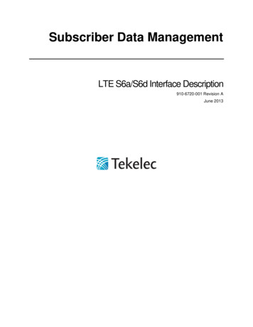
MX Series Subscriber Management for Customer VLANsImplementation GuideIntroductionThis implementation guide describes how to configure subscriber management on Juniper Networks MX Series 3DUniversal Edge Routers when they are used as Broadband Network Gateways and support customer VLANs. Subscribermanagement is performed by the Broadband Network Gateway (BNG) router, which is a key component of theoverall Juniper multiplay architecture depicted in Figure 1. Subscriber management is also called AAA (authentication,authorization, and accounting), or AAAA (which adds address assignment). This includes the following: Authentication: The first step is to verify that the person attempting to use the network is who they claim to be.Dial-up users must provide a user-id and password, while a mobile phone will quietly send an electronic identifier.In a modern wireline “always on” broadband network (such as xDSL, FTTx, or cable), only authorized users shouldhave network access, but this is typically still validated by the network operator. Authorization: This step determines which network resources the subscriber is allowed to use. For example, isthe subscriber allowed to access at 512 Kbps, 1 Mbps, or 5 Mbps? Has the subscriber signed up for VoIP service?Whether or not Point-to-Point Protocol over X (PPPoX) is used, subscriber information is commonly in a RADIUSserver. When a subscriber enters the network, the edge router sends a message to the RADIUS server asking whatservices the subscriber has access to, and the server responds with this information. Address assignment: As new devices enter the network, they request an IP address using Dynamic HostConfiguration Protocol (DHCP). Different types of clients, such as set-top boxes (STBs), PCs, and VoIP phones,often receive their addresses from different DHCP servers. In fact, set-top boxes often must receive their IPaddresses from the middleware server system. Even when devices (such as PCs and VoIP phones) receive theiraddresses from the same server, the addresses may come from different address pools. Accounting: This is the tracking of network and resource usage by the subscriber.The AAA functions are tightly intertwined. In theory, the subscriber cannot access the network until an IP address isassigned; however, it is unwise to assign an address until the subscriber is authenticated.This document is based on testing performed at Juniper Networks using a network supporting broadcast IPTV, video ondemand, VoIP, and Internet traffic concurrently.EX SeriesLocalChannelsMX Serieswith BNGDSLAMRemote Terminal(RT)Central OfficeTerminal (COT)WANEdgeVHOVSOMETROCOREMX SeriesNationalChannelsSUPERCOREMX SeriesEX SeriesContent &ApplicationsTransitFigure 1: Juniper multiplay reference architecture 2016, Juniper Networks, Inc.3
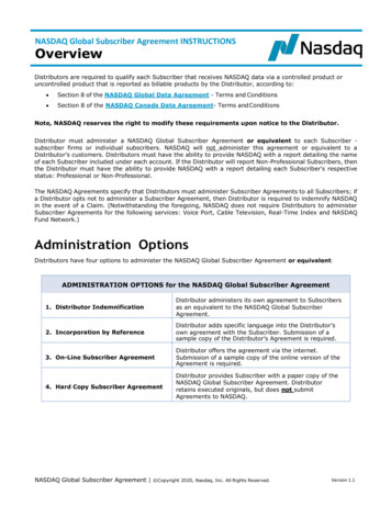
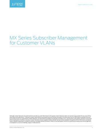
MX Series Subscriber Management for Customer VLANsImplementation GuideScopeThis Implementation guide describes the configuration on an MX Series router as a Broadband Network Gateway toprovide subscriber access, authentication, and service creation, activation, and deactivation using customer VLANs.Figure 2 highlights the key network elements covered in this document. Subscriber management support is configuredon the MX Series device closest to the multiservice access node (MSAN).LocalChannelsEX SeriesMX Serieswith BNGDSLAMRemote Terminal(RT)Central OfficeTerminal (COT)NationalChannelsMX SeriesVHOVSOMETROCOREWANEdgeSHESUPERCOREMX SeriesEX SwitchContent &ApplicationsTransitFigure 2: Network topologySpecifically, this document covers two implementations. First, it describes the configuration of static customerVLANs and multicast VLANs on a single physical interface. Second, it describes the configuration of dynamiccustomer VLANs on a physical interface.Loopback addresses: 11.3.3.3/32 (primary) 103.0.1.1 (preferred forVLAN 306/Video)Scenario 1: Static CVLAN/MVLANge-2/0/8ge-1/2/343.1.1.1 Static Customer VLANs Static Multicast VLAN Static RG Management l-BeltedRADIUS11.28.11.177Scenario 2: Dynamic CVLAN, Static MVLAN192.168.0.2 Dynamic Customer VLANsge-1/2/3 Static Multicast VLAN Static RG Management VLANMX SeriesBroadbandNetwork ddleware/DHCPServerMX SeriesFigure 3: Subscriber management focus detailsDesign ConsiderationsJuniper supports a wide range of methods for supporting residential subscribers.VLAN ModelsThe most fundamental decision is how VLANs should be configured to carry subscriber traffic across the accessnetwork. There are two methods, which for completeness are summarized below. This document covers the customerVLAN implementation. Service VLAN (S-VLAN). As depicted in Figure 4, a given VLAN carries one service to all subscribers. There areseparate VLANs for voice, Internet access, and IPTV. Customer VLAN (C-VLAN). In this model, a given VLAN carries all services to one subscriber. This requires manymore VLANs but simplifies network operations since each subscriber is mapped to a VLAN. However, not allMSANs support this model. 2016, Juniper Networks, Inc.4
MX Series Subscriber Management for Customer VLANsDataImplementation GuideMX SeriesVoice VideoMSANDataService VLAN (Data)Service VLAN (Voice)Service VLAN (Video)Voice Video Each service VLAN carries oneservice to many subscribersDataVoice VideoFigure 4: Service VLAN modelA common variation adds a single shared multicast VLAN (M-VLAN) which carries multicast traffic (broadcast IPTV) toall subscribers. This eliminates the need to send a channel multiple times across the network, once to each subscriberviewing the content. In addition, a C-VLAN model always requires service VLANs for managing network equipment suchas routers, MSANs, Residential Gateways (RGs), and STBs.DataMX Serieswith BNGVoice VideoMSANDataDataVoice VideoVoice VideoCustomer VLAN (subscriber #1)Customer VLAN (subscriber #2)Customer VLAN (subscriber #3)Multicast VLAN (video) M-VLAN carries IPTV and IGMPtraffic for all subscribers C-VLANs carry all other traffic foreach subscriberFigure 5: Customer VLAN (with optional multicast VLAN) modelAdding IP ClientsClient connections may be defined statically or dynamically. Using static definitions quickly becomes cumbersome andinefficient to provision new subscribers, so dynamic definitions are more commonly deployed. There are two differentdynamic models available within Junos OS, which differ according to whether the VLANs are also created dynamically.For C-VLANs, autosensing creates both VLAN and subscriber definitions dynamically. For S-VLANs, demultiplexing(demuxing) creates client definitions dynamically but uses predefined VLANs.Stacking Customer VLANsIf there are less than 4,095 subscribers connected to a BNG interface, then a single VLAN tag can be used to uniquelyidentify each subscriber. However, there can easily be tens of thousands of subscribers on the network. In this case,VLAN stacking is used to bypass the VLAN scaling limit as illustrated in Figure 6. The process is as follows:BNGPort iceIPTVDataVoiceIPTVDataVoiceIPTVMX SeriesBroadbandNetwork GatewayMX Series(WAN Switch)C-VLANC-VLANC-VLANC-VLANC-VLANC-VLANOuter VLAN for trafficto/from MSAN 1C-VLANC-VLANC-VLANC-VLANC-VLANC-VLANOuter VLAN for trafficto/from MSAN 2Figure 6: VLAN stacking for C-VLAN/M-VLAN 2016, Juniper Networks, Inc.5
MX Series Subscriber Management for Customer VLANsImplementation Guide The BNG adds the appropriate VLAN tags. For the C-VLANs, the outer tag identifies the destination MSAN,while the inner tag identifies the specific subscriber on that MSAN. IPTV content is also being delivered to twosubscribers via the M-VLAN, which does not require stacking since it is shared by all subscribers on the BSE port. The Layer 2 switch uses the outer tag to determine where to forward the packet. It removes the outer tag on theC-VLANs (only) before forwarding the packets to the MSAN. The MSAN adjusts VLAN tags and forwards the information to each subscriber. There are several variations to this:-- All traffic to a given subscriber is merged onto the C-VLAN for that subscriber.-- All VLAN tags may be swapped to a common value or removed. This allows the operator to deploy a singleconfiguration for all connected home gateway routers. Keeping the VLAN tags allows specifying the trafficpriority using Ethernet’s 802.1p bits carried in the VLAN tag.Note that when using stacking, the “inner” C-VLAN values may be repeated within each stack.Additional VLANsAdditional VLANs are often required for MSAN management, RG management, and booting of set-top boxes. These areconfigured similarly to the M-VLAN.IP Address AssignmentIP addresses can be assigned to network devices in several ways: The IP address can be preconfigured. This is done for the MSAN. The IP address can be assigned by a DHCP server embedded within the router. This is the role of Junos OS’ “localDHCP server” subsystem, and is used for the residential gateways. All PCs and VoIP equipment sit behind the RG,which hides the other devices by implementing Network Address Translation (NAT). The IP address can be assigned by a standalone (“external”) DHCP server. This is done for the STBs.This document uses a combination of these techniques to illustrate the options.Subscriber DatabaseInformation about subscribers/clients may be defined in various ways: The information can be statically configured in the router. In a service VLAN network using dynamic addressassignment, this results in having the same services for all subscribers. This information can be stored in a DHCP server, and sent as a DHCP option during the address assignmentprocess. Some smaller, newer deployments use this technique. However, DHCP supports a limited set ofcapabilities. The information can be stored in a RADIUS server and sent as RADIUS attributes when the client enters thenetwork. This is the original method supported by the DSL Forum, so it has been implemented by virtually all Tier 1vendors and early entrants. It is the most mature implementation, with the widest range of supported informationwhich can be pushed down to the router to specify the client’s authorizations.This document uses a RADIUS server as the subscriber repository. Table 1 summarizes the VLAN and IP addressallocations used in this setup.Table 1: VLAN Allocations and Associated Loopback IP AddressesVLANAllowed RangeConfiguredPreferred(Loopback)Source IP AddressIP AddressesDHCP ServerSubnetManagementDSLAM -4094 (Outer)1001NoneJunos .1.1.x/24Services 2016, Juniper Networks, Inc.6
MX Series Subscriber Management for Customer VLANsImplementation GuideProtocol OperationProviding AAA service may involve RADIUS authentication and DHCP address assignment. The DHCP server assigningthe addresses may be integrated into an MX Series router (local server) or may be a standalone device (external server).Figure 7 overviews the AAAA process when using an external DHCP server.BroadbandNetworkGatewayIP Client:Set-Top BoxDHCP Discover (broadcast)RADIUSServerDHCPServerDHCP Discover (unicast)DHCP Offer (IP 100.1.1.2)DHCP Request (IP 100.1.1.2)DHCP Acknowledgement (100.1.1.2)CHAP (user voip, password 123)ACKRADIUS Req (Interface 1/2/4.100)RADIUS Auth (parameters)Figure 7: Adding new client using DHCP external serverThe following general sequence occurs during access configuration for a DHCP client:1. The client uses a standard DHCP process to get an IP address.a. Client issues a DHCP DISCOVER to request an IP address. The MX Series intercepts this request, substituting thedestination address to that of defined DHCP servers, and forwards the message. The MX Series will forward therequest to each defined DHCP address. The router DHCP component recognizes the DHCP message and adds theclient (without an assigned IP address) to the router session database.b. The DHCP server issues a DHCP OFFER, proposing an IP address for the client. The client may receive multipleoffers.c. The client responds with a DHCP REQUEST, indicating the preferred address to use. The request is forwarded to allDHCP servers.d. Finally, the DHCP server responds with a DHCP ACKNOWLEDGEMENT, to confirm that the address has beenaccepted.2. If RADIUS is configured:a. The router “logs into” the RADIUS server by sending a user-id and password. Typically, Challenge HandshakeAuthentication Protocol (CHAP) is used.b. The login request is acknowledged.c. The router sends a RADIUS REQUEST message, essentially asking for information about this subscriber’spermissions.d. The RADIUS server responds by sending a RADIUS RESPONSE with the information, which is sent using IETFstandard and Juniper-specific RADIUS attributes.3. At this point, the router sets the capabilities for this subscriber.a. The router adds RADIUS authorization information to the router session database.b. The router combines the dynamic profile with the RADIUS authorization information.c. The router alerts all internal applications involved with the subscriber access (for example, routing protocols,dynamic firewall, and dynamic class of service). 2016, Juniper Networks, Inc.7
MX Series Subscriber Management for Customer VLANsImplementation GuideFigure 8 depicts the AAAA process using the integrated DHCP server.IP Client:Residential GatewayBroadbandNetworkGatewayRADIUSServerDHCP Discover (broadcast)CHAP (user internet, password 123)ACKRADIUS Req (Interface 1/2/4.0)RADIUS Auth (Framed-IP-Pool internet; other attributes)DHCP Offer (IP 100.1.1.2)DHCP Request (IP 100.1.1.2)DHCP Acknowledgement (100.1.1.2)Figure 8: Adding new client using DHCP local serverWhen using local server, the IP address is assigned by the router instead of by an external server. The IP address may beassigned in one of three ways: The RADIUS server tells the MX Series router the name of the address pool to use (shown), or The RADIUS server tells the MX Series router what specific IP address to use, or The RADIUS server provides no information, allowing the MX Series router to follow whatever procedure has beendefined within the MX Series.ImplementationA subscriber service is based on the combination of a defined dynamic profile and attributes configured throughauthentication. Dynamic profiles can include dynamic firewall filters, class-of-service (CoS) settings, and Internet GroupManagement Protocol (IGMP) settings that define access limits for subscribers and the scope of a service granted to thesubscriber once access is obtained.The remainder of this document walks through how the broadband services edge router is configured to support this. Itis organized as follows: Loopback addresses Defining RADIUS servers and profiles Defining DHCP servers Interfaces (ports and VLANs) Quality of Service (QoS)Loopback AddressLoopback addresses are not tied to a physical interface. There is one box-wide loopback address, plus one for eachfunction that uses an external DHCP server. In our case, there is one function using an external DHCP server—the set-topbox. When communicating to the external DHCP server to get an address for an STB, the router specifies 103.1.0.1 as thesource address.lo0 {unit 0 {family inet {address 11.3.3.3/32 {primary;}}}} 2016, Juniper Networks, Inc.8
MX Series Subscriber Management for Customer VLANsImplementation GuideDefining RADIUS Servers and ProfilesThere are three steps to defining and configuring RADIUS servers:1. Specify the available RADIUS servers2. Configure profile(s) that specify which RADIUS server(s) to contact (multiple profiles can be created)3. Specify which profile(s) will be usedSpecifying RADIUS ServersThe ability to operate with two different RADIUS servers was validated in Juniper testing. 42.1.1.2 is the address used forJuniper’s Steel-Belted Radius server, while 43.1.1.2 is FreeRADIUS.access {radius-server {42.1.1.2 {port 1812;secret “ 9 6Tgs/tO1IcrlMOBxNbwg4”; ## SECRET-DATA}43.1.1.2 {port 1812;secret “ 9 DwjqfTQn9Cuf5IEyrvM”; ## SECRET-DATA}}}Defining RADIUS ProfilesThe access profile specifies which RADIUS servers should be checked. This example includes a single profile named“ISE” which checks two RADIUS servers. One server (42.1.1.2) is Juniper’s SBR Carrier RADIUS server, while the other isFreeRADIUS. Note that only one server was active at a time during our testing.The nas-identifier is the address with which the RADIUS server communicates. This configuration uses a loopbackaddress as the nas-identifier.profile ISE {authentication-order radius;radius {authentication-server [42.1.1.2 43.1.1.2];options {nas-identifier 11.3.3.3;}}radius-server {42.1.1.2 {port 1812;secret “ 9 q.5Fn6Au0IF3SrvMXx”; ## SECRET-DATA}43.1.1.2 {port 1812;secret “ 9 cytSeWLX-bwgW8ZUHkPf”; ## SECRET-DATA}}Access ProfileFinally, the access-profile command specifies which profile will be used.access-profile ISE; 2016, Juniper Networks, Inc.9
MX Series Subscriber Management for Customer VLANsImplementation GuideDefining DHCP ServersIP addresses can be assigned by the router (local server) or by an external DHCP server. In addition, an IP address may besent by the RADIUS server. If different IP addresses are returned by the various servers, the following is the priority order: External DHCP server: This takes precedence over the address (or pool) from the RADIUS server. RADIUS server: If an address (or pool) is sent by the RADIUS server, this takes precedence over the IP addresswhich would otherwise be assigned by a router’s local (integrated) DHCP server. Local DHCP server: This address pool will be used when no other servers specify an address to use.Table 1 shows which device assigns the IP addresses. Additional pools can easily be created to support additionaldevices. For example, if this port supports OLTs as well as digital subscriber line access multiplexers (DSLAMs), differentaddress pools could be created that support clients attached to the OLT (if desired).Configuring Local DHCP ServerConfiguring the local server includes two pieces: Configuring the address pools which will be used when assigning IP addresses Configuring RADIUS accessConfiguring Address PoolsThis first portion defines the IP address pools used by the DHCP local server (local server addresses that are assignedby the MX Series) to assign addresses. Only an “Internet” pool is defined, since only VLAN 101 (PCs) get their IPaddresses assigned by the local DHCP server.address-assignment {pool cvlan {family inet {network 197.20.0.0/16;range ip {low 197.20.0.1;high 197.20.255.254;}dhcp-attributes {maximum-lease-time 10000;grace-period 100;}}}Configuring RADIUS AccessThe next piece is to define parameters for communicating with the RADIUS server. As noted in the configuration, thispool only applies to traffic coming from ge-1/2/4.0—that is, all traffic (VLANs) on the specified physical interface.Pool-match-order specifies that the pool name to use will be sent by the RADIUS server (IETF attribute 88). If thisparameter is absent, then the local server will use the IP address specified by the RADIUS server (IETF attribute 8). IfRADIUS does not send an IP address, then the local server will assign an IP address from its own pool.Note that the configuration also specifies that an external dynamic profile called “subscriber” will be used. This is thetemplate which will be used to create subscriber connections as new clients enter the network.system {services {dhcp-local-server {traceoptions {file dhcp size 10m;flag all;}pool-match-order {external-authority; 2016, Juniper Networks, Inc.10
MX Series Subscriber Management for Customer VLANsImplementation Guide}group cvlan {authentication {password lab123;username-include {user-prefix cvlan;}}dynamic-profile dhcp-profile;interface ge-1/2/4.0;}Configuring DHCP RelayThis section shows the DHCP definition for clients using external servers. When doing this, the router must convert thebroadcasted DHCP request into a directed unicast request. This function is one piece of the DHCP Relay function. Inaddition, this is where the IP addresses of external DHCP servers are specified.How do these servers know what type of device the requesting client is, so that the appropriate IP address can beassigned? That information typically is provided in one of two ways. First, DHCP flows include a CHADDR field, whichis the media access control (MAC) address of the device that initiated the DHCP request. The first half of this field is avendor identifier field. For example, CHADDR 242337xxxxxx is manufactured by Avaya, and in our network, this is alwaysa VoIP phone. The other alternative is that the equipment may add a DHCP Option 60 field. This option allows the clientto send information identifying what type of device it is or what pool to use. In either case, the router does not modifythese fields or influence the address assignment process.In addition to forwarding the request to the external DHCP server, the requests trigger an authentication call to theRADIUS server. For DHCP requests received on interface ge-1/2/4.0 (that is, any VLAN on the specified physicalinterface), the user-prefix “cvlan” is included in the RADIUS login request to identify the type of client. In our case, “cvlan”is the entire login name. In other cases, this prefix may be added to other information such as the MAC address, to moretightly identify the client.Note that the middleware group (for IPTV set-top boxes) specifies that an external dynamic profile called “dhcp-profile”will be used. This is the template used to create subscriber connections as new clients enter the network.DHCP relay converts a broadcasted DHCP request into a unicast request and forwards it to all of the specified servers.Only DHCP servers with pools matching the request will respond by offering an IP address.While RADIUS can also be used to authenticate RGs, this is not done in this setup.forwarding-options {dhcp-relay {server-group {middleware {192.168.0.2;}}group middleware {active-server-group middleware;authentication {password lab123;username-include {user-prefix video;}}dynamic-profile dhcp-profile;interface ge-1/2/4.0;}}} 2016, Juniper Networks, Inc.11
MX Series Subscriber Management for Customer VLANsImplementation GuideScenario 1: Interface Definitions for Statically Defined VLANsThe snippet below shows a configuration for an interface supporti
Subscriber management is also called AAA (authentication, authorization, and accounting), or AAAA (which adds address assignment). This includes the following: . each subscriber Data Voice Video MX Series (WAN Switch) BNG Port 1/1/1 MX Series Broadband Network Gateway Data Voice IPTV C-VLAN C-VLAN C-VLAN Data Voice IPTV