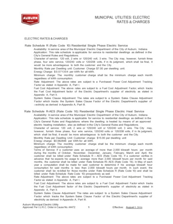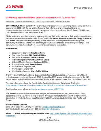
Transcription
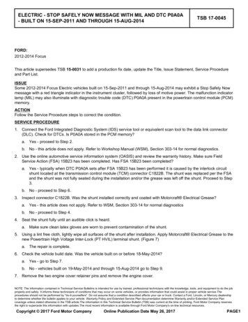
ELECTRIC - STOP SAFELY NOW MESSAGE WITH MIL AND DTC P0A0A- BUILT ON 15-SEP-2011 AND THROUGH 15-AUG-2014TSB 17-0045FORD:2012-2014 FocusThis article supersedes TSB 15-0031 to add a production fix date, update the Title, Issue Statement, Service Procedureand Part List.ISSUESome 2012-2014 Focus Electric vehicles built on 15-Sep-2011 and through 15-Aug-2014 may exhibit a Stop Safely Nowmessage with a red triangle indicator in the instrument cluster, followed by loss of motive power. The malfunction indicatorlamp (MIL) may also illuminate with diagnostic trouble code (DTC) P0A0A present in the powertrain control module (PCM)memory.ACTIONFollow the Service Procedure steps to correct the condition.SERVICE PROCEDURE1. Connect the Ford Integrated Diagnostic System (IDS) service tool or equivalent scan tool to the data link connector(DLC). Check for DTCs. Is P0A0A stored in the PCM memory?a. Yes - proceed to Step 2.b. No - this article does not apply. Refer to Workshop Manual (WSM), Section 303-14 for normal diagnostics.2. Use the online automotive service information system (OASIS) and review the warranty history. Make sure FieldService Action (FSA) 15B23 has been completed. Has FSA 15B23 been completed?a. Yes - typically when DTC P0A0A sets after FSA 15B23 has been performed it is caused by the interlock circuitshunt located at the transmission control module (TCM) connector C1822B. The shunt was replaced per the FSAand the shunt was not fully seated during the installation and/or the grease was left off the shunt. Proceed to Step3.b. No - proceed to Step 6.3. Inspect connector C1822B. Was the shunt installed correctly and coated with Motorcraft Electrical Grease?a. Yes - this article does not apply. Refer to WSM, Section 303-14 for normal diagnosticsb. No - proceed to Step 4.4. Seat the shunt fully until an audible click is heard.a. Make sure clean latex gloves are worn to prevent contamination of the shunt.5. Using a lint free cloth, lightly wipe all surfaces of the shunt after installation. Apply Motorcraft Electrical Grease to thenew Powertrain High Voltage Inter-Lock (PT HVIL) terminal shunt. (Figure 7)a. The repair is complete.6. Check the vehicle build date. Was the vehicle built on or before 18-May-2014?a. Yes - go to Step 7.b. No - vehicles built on 19-May-2014 and through 15-Aug-2014 go to Step 9.7. Remove the two engine cover retainer pins and remove the engine cover.NOTE: The information contained in Technical Service Bulletins is intended for use by trained, professional technicians with the knowledge, tools, and equipment to do the jobproperly and safely. It informs these technicians of conditions that may occur on some vehicles, or provides information that could assist in proper vehicle service.Theprocedures should not be performed by "do-it-yourselfers". Do not assume that a condition described affects your car or truck. Contact a Ford, Lincoln, or Mercury dealershipto determine whether the bulletin applies to your vehicle. Warranty Policy and Extended Service Plan documentation determine Warranty and/or Extended Service Plancoverage unless stated otherwise in the TSB article.The information in this Technical Service Bulletin (TSB) was current at the time of printing. Ford Motor Company reservesthe right to supercede this information with updates.The most recent information is available through Ford Motor Company's on-line technical resources.Copyright 2017 Ford Motor CompanyOnline Publication Date May 26, 2017PAGE1
TSB 17-0045 (Continued)8. Inspect the high voltage (HV) wire harness. Are the HV wires individually wrapped in convolute? (Figure 1)Figure 1 - Article 17-0045a. Yes - HV wire harness update is not required. Proceed to Step 22.b. No - proceed to Step 9.9. Disconnect the HV battery service disconnect. Refer to WSM, Section 414-03.10. Disconnect the TCM connector. (Figure 1)11. Use a pair of round/blunt nose scissors to cut the single convolute between the wires down to the black tape at the dashbracket and discard the cut convolute. Peel back the convolute as you cut for better visibility. (Figure 2)Figure 2 - Article 17-0045a. To avoid damage to the HV wire harness, a razor blade, utility knife or similar tool should not be used for cutting theconvolute and tape.12. Install the abrasion sleeves individually over each HV wire. (Figure 3)PAGE2
TSB 17-0045 (Continued)Figure 3 - Article 17-004513. Install tie-straps to the HV wire harness in the sequence shown. Install the tie-straps so they are facing away from eachother. Cut off excess length of the tie-straps. (Figure 4)Figure 4 - Article 17-004514. Replace the four TCM connector terminal springs using a terminal release tool, pick or bent paper clip. Do not scratch ordamage the terminal surface or spring grooves. (Figure 5)PAGE3
TSB 17-0045 (Continued)Figure 5 - Article 17-0045a. Each TCM terminal contains two springs.b. Place the springs into their correct position and seat in the grooves.15. On the TCM connector, locate the PT HVIL terminal shunt locking tab access hole. Using an angled pick, press the tabwhile pulling the shunt out of the connector and discard the shunt. (Figure 6)Figure 6 - Article 17-004516. Install new shunt. The shunt is not fully seated during installation until an audible click is heard.a. Make sure clean latex gloves are worn to prevent contamination of the new shunt.17. Using a clean lint free cloth, lightly wipe all surfaces of the shunt after installation. Apply Motorcraft Electrical Grease tothe new PT HVIL terminal shunt. (Figure 7)PAGE4
TSB 17-0045 (Continued)Figure 7 - Article 17-004518. Connect and disconnect the TCM connector.a. Verify all components remain in the correct position.19. Reconnect the TCM connector.20. Install the engine cover and the two engine cover retainer pins.21. Connect the HV battery service disconnect. Follow the WSM procedures in Section 414-03A.22. Reprogram the PCM to the latest calibration using IDS release 105.01 or higher. Make sure you are connected to theinternet when entering module programming to obtain the latest updates. Calibration files may also be obtained atwww.motorcraftservice.com.PART NUMBERPART NAMEXG-12Motorcraft Electrical GreaseCM5Z-15K607-AHigh Voltage Harness KitOTHER APPLICABLE ARTICLES: 15B23OPERATIONDESCRIPTIONTIME170045A2012-2014 Focus Electric: Retrieve DTCs, Inspect And Correct Shunt IfNecessary Following The Service Procedure (Do Not Use With AnyOther Labor Operations)0.3 Hr.170045B2012-2014 Focus Electric: Retrieve DTCs, Inspect And Correct Shunt IfNecessary Following The Service Procedure, Inspect The HV Wires OnlyAnd Reprogram The PCM (Do Not Use With Any Other LaborOperations)0.6 Hr.170045C2012-2014 Focus Electric: Retrieve DTCs, Inspect And Update The HVWires, Replace The Shunt And Reprogram The PCM (Do Not Use WithAny Other Labor Operations)1.1 Hrs.WARRANTY STATUS:Eligible Under Provisions Of New Vehicle Limited Warranty Coverage And Emissions Warranty CoverageWarranty/ESP coverage limits/policies/prior approvals are not altered by a TSB. Warranty/ESP coverage limits aredetermined by the identified causal part and verified using the OASIS part coverage tool.DEALER CODINGBASIC PART NO.14A318PAGE5CONDITION CODE12
WARRANTY STATUS: Eligible Under Provisions Of New Vehicle Limited Warranty Coverage And Emissions Warranty Coverage Warranty/ESP coverage limits/policies/prior approvals are not altered by a TSB. Warranty/ESP coverage limits are determined by the identified causal part and verified using the OASIS part coverage tool. DEALER CODING BASIC PART NO.