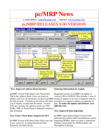
Transcription
Additional JFW Brochures50 Ohm ComponentsBrochureAn overview of JFW's 50 Ohmcomponents, covering frequenciesup to 18 GHz.Programmable AttenuatorsManually Variable AttenuatorsFixed AttenuatorsTerminationsRF SwitchesPower Dividers and CombinersImpedance Matching PadsDC BlocksRF DetectorsBias Taps75 Ohm ComponentsBrochureSee what JFW has to offer for cableTV and other 75 Ohm applications,including:Programmable AttenuatorsRotary AttenuatorsFixed AttenuatorsTerminationsRF SwitchesPower DividersImpedance Matching PadsDC BlocksRF DetectorsBias Taps
www.jfwindustries.comJFW's Quality Policy“JFW is committed to anticipating and exceeding customer’s requirementsand expectations through cost-competitive, quality products and servicesthat are delivered on time and through continual improvements to our qualitymanagement system.”JFW's Standard Terms and ConditionsJFW Industries, Inc. has standard terms of Net 30 days with approved credit.Alternate methods of payment include MASTERCARD,American Express, VISA, COD or ADVANCE PAYMENT.International Payment Terms are ADVANCE PAYMENT orMASTERCARD, American Express and VISA.Any other payment terms must be negotiated in advance.Shipping terms are FOB JFW Ind for Domestic Customers andFCA JFW Ind for International Customers.ALL SHIPPING CHARGES will be PREPAID and ADDED TO THE INVOICE orSHIPPED COLLECT VIA YOUR DESIGNATED FREIGHT CARRIER.JFW INDUSTRIES WARRANTYJFW PRODUCTS ARE WARRANTED AGAINST DEFECTS IN WORKMANSHIP AND MATERIAL UNDER NORMAL USE ANDSERVICE AS FOLLOWS: (2) TWO YEARS FROM DATE OF SHIPMENT FOR ALL FIXED AND SOLID STATE PRODUCTS.(1) ONE YEAR FROM DATE OF SHIPMENT FOR ALL MECHANICAL AND ELECTRO-MECHANICAL PRODUCTS. JFWINDUSTRIES’ ONLY OBLIGATION UNDER THIS WARRANTY IS TO REPAIR OR REPLACE, AT ITS FACTORY, ANY JFWPRODUCT OR PART THEREOF THAT IS RETURNED TO JFW INDUSTRIES BY THE ORIGINAL PURCHASER WITHINTHE WARRANTY PERIOD.THE WARRANTY STATED ABOVE IS YOUR SOLE AND EXCLUSIVE WARRANTY AND IS IN LIEU OF ALL OTHERWARRANTIES, EXPRESSED OR IMPLIED, INCLUDING, BUT NOT LIMITED TO, ANY IMPLIED WARRANTY OR FITNESSFOR ANY PARTICULAR PURPOSE. JFW INDUSTRIES SHALL NOT BE LIABLE FOR ANY DIRECT OR CONSEQUENTIALINJURY, LOSS OR DAMAGE INCURRED THROUGH THE USE, OR INABILITY TO USE, ANY JFW INDUSTRIES PRODUCT.JFW Industries, Inc.JFW International Sales5134 Commerce Square DriveIndianapolis, Indiana 46237Call-317-887-1340Toll Free-877-887-4JFW (4539)Fax-317-881-6790E-mail: sales@jfwindustries.com7 Albion RoadSouth BenfleetEssex, UK SS7 5PUPhone 44 7768-662666Fax 44 1268-795377E-mail: simon@jfwindustries.comCatalog 18Printed 02-2016
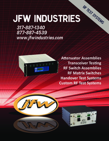
Programmable Attenuator Assemblies Single or multiple programmable attenuators 19" rack or benchtop packages Remote control via Ethernet, RS-232 or GPIB Front panel manual control available4 attenuators10" x 10" x 4.5" benchtop enclosure4 attenuators2RU 19" rack enclosure24 attenuators3RU 19" rack enclosureNo front panel controlN inputs on rear / SMA outputs on front9 attenuators12" x 10" x 5" benchtop enclosureVisit www.jfwindustries.com/PA for model numbers.4JFW Industries317-887-1340sales@jfwindustries.com
Programmable Attenuator AssembliesMini Benchtop Series Economy series with simplified front panel controlVisually monitor attenuation settings on all portsCan manually perform handovers via front panel toggle switchesAvailable with 1, 2, 3 or 4 attenuatorsRemote commands and GUI identical to 19" rack modelsFrequency coverage 30-3000 MHz or 200-6000 MHz1 attenuator – N Connectors6.75" x 6.75" x 3.25" benchtop boxAlso available with SMA connectors.2 attenuators – N Connectors9" x 9" x 4" benchtop boxAlso available with SMA connectors.4 attenuators – SMA Connectors9" x 9" x 4" benchtop boxVisit www.jfwindustries.com/BA for model numbers.5JFW Industries317-887-1340sales@jfwindustries.com
Handover SystemsFull Fan-Out Allows for simultaneous testing of multiple devices Cost scales with number of programmable attenuatorsf1f2f3IN 1IN 2IN ider/Combiner0dBOUT 11X3OUT 21X3OUT dBf1f1f2 Lower cost due to fewer attenuators (3 vs 9 for full fan-out in this example) Used for testing multiple devices in parallelf1IN 1ProgrammableAttenuators95dBf2IN 210dBf3IN 30dB1X31X3Divider/CombinerDivider/CombinerOUT 2OUT 3f1f1f1f2f2f2f3f3f3Manual Handover SystemsManual versions using rotary attenuators instead of programmables are also available.Visit www.jfwindustries.com/Handover for model numbers.6JFW C (Limited Fan-Out Configuration)OUT 1f1f2f3f3
RF Switch Assemblies Assemblies can contain a single switch or a bank of switches Switches can be solid-state or electro-mechanical Assemblies can also include other components, such as programmable attenuators or power dividers(2) 1P4T solid-state 50 Ohm switches2RU 19" rack enclosure(8) 1P4T electro-mechanical switches (DC-18 GHz)Expandable to 12 switches3RU 19" rack enclosure(10) 1P4T solid-state 75 Ohm switches4RU 19" rack enclosureVisit www.jfwindustries.com/SA for model numbers.7JFW Industries317-887-1340sales@jfwindustries.com
Matrix SwitchesCommon Highway Matrix SwitchesIN 1IN 2IN 3IN 4 One active path Very cost effective1P4TRF Switch1P6TRF SwitchOUT 1OUT 2OUT 3OUT 4OUT 5OUT 6Blocking Matrix Switches Multiple active paths. Number of active paths determined by the lesser of the # ofinputs or outputs. So for a 4x8 Blocking Matrix Switch, there would be a maximum of 4simultaneously active pathsIN 1IN 2IN 31P3TRF Switch1P3TOUT 1RF SwitchRF Switch1P3TRF Switch1P3TOUT 21P3T1P3TOUT 3RF SwitchRF SwitchLC Blocking Matrix Switches Multiple active paths. Number of active paths determined by the size of the matrix Additional switches increase the maximum number of inputs and outputs Less costly than a standard Blocking Matrix Switch with the same number of portsIN 1IN 2IN 3IN 4IN 5IN 6IN 7IN 8IN 9IN 101P4TRF Switch2 X 2 Blocking Matrix1P2T1P2TRF SwitchRF Switch1P2T1P6T1P2TRF SwitchRF SwitchRF Switch1P4TRF Switch1P4TRF Switch10 Inputs, 8 outputs2 simultaneous active pathsVisit www.jfwindustries.com/MS for model numbers.8JFW Industries317-887-1340sales@jfwindustries.comOUT 1OUT 2OUT 3OUT 4OUT 5OUT 6OUT 7OUT 8
Non-Blocking Matrix SwitchesNon-Blocking Matrix SwitchesIN 1IN 2IN 31X3Divider/Combiner1P3TOUT 11P3TOUT 21P3TOUT 3RF Switch1X3Divider/CombinerRF Switch1X3Divider/CombinerRF SwitchSuper-Non-Blocking Matrix SwitchesRF Switchesf1f2f3IN 1IN 2IN 1X3Divider/Combiner1X3Divider/Combiner1P1T ON1P1T OFF1X3OUT 1f1f31X3OUT 2f3OUT 3f1f2f3Divider/Combiner1P1T ON1P1T OFF1P1T OFFDivider/Combiner1P1T ON1P1T ON1X31P1T ONDivider/Combiner1P1T ONInterconnects8163264128256512Matrix switch costs scale withthe number of interconnectsVisit www.jfwindustries.com/MS for model numbers.9JFW Industries317-887-1340sales@jfwindustries.com
Transceiver Test Systems1X51X51X51X5Ports Attenuators465106158281266161202427632496ATT #15ATT #13ATT #14ATT #10ATT #11ATT #12ATT #6ATT #7ATT #8ATT #9ATT #1ATT #2ATT #3ATT #4ATT #5ProgrammableAttenuatorsFull /CombinerPort 1Port 2Port 3Port 4Port 5Port 66 input transceiver test systemEach port connected to every other port15 attenuatorsTransceiver TestSystem cost scaleswith the numberof programmableattenuators1X41X41X4ATT #11ATT #12ATT #9ATT #10ATT #5ATT #6ATT #7ATT #8ATT #1ATT #2ATT #3ATT #4ProgrammableAttenuatorsVariation 1: Unconnected r/CombinerPort 1Port 2Port 3Port 4Port 5Port 6(Ant 1)(Ant 2)(Ant 1)(Ant 2)(Ant 1)(Ant 2)Device 1Device 2Device 36 input transceiver test systemEach block of 2 ports do not need to interconnect12 attenuatorsVisit www.jfwindustries.com/PMA for model numbers.10JFW Industries317-887-1340sales@jfwindustries.com
Transceiver Test Systems1X21X21X21X2ATT #6ATT #5ATT #4ATT #3ATT #2ATT #1ProgrammableAttenuatorsVariation 2: Separate Tx & inerPort 1Port 2Port 3Port 4Port 5Port 6(Tx)(Rx)(Tx)(Rx)(Tx)(Rx)Radio 1Radio 2Radio 36 input transceiver test systemTesting 3 radios with separate Tx and Rx ports6 attenuators8 port Transceiver Test System28 programmable attenuators5RU 19" rack enclosureVisit www.jfwindustries.com/PMA for model numbers.11JFW Industries317-887-1340sales@jfwindustries.com
Transceiver Test Systems with RF Hubs1 RF HubIN/OUT 1ProgrammableAttenuators0-127 x 1dBIN/OUT 20-127 x 1dBIN/OUT 30-127 x 1dBIN/OUT 40-127 x 1dBIN/OUT 50-127 x 1dBIN/OUT 60-127 x 1dBRF Hub6 Port Divider/Combinerwith star configurationConfigurable with 2 RF HubsIN/OUT 1ProgrammableAttenuators0-95 x 1dBIN/OUT 20-95 x 1dBIN/OUT 30-95 x 1dBIN/OUT 40-95 x 1dB1P2TJ1J2RF Hub #11P2TJ1J24 Port Divider/Combinerwith star configuration1P2TJ1J2RF Hub #21P2TJ1J24 Port Divider/Combinerwith star configurationRF SwitchRF SwitchRF SwitchRF SwitchVisit www.jfwindustries.com/PMA for model numbers.12JFW Industries317-887-1340sales@jfwindustries.com
Other ProductsControl BoxesUsed to interface with multipleJFW programmable attenuatorsor RF switchesPanel Mounted Rotary Attenuators(8) rotary attenuators mounted in a2RU 19" rack panelPanel Mounted Power DividersAttenuator Assemblies(4) 100W fixed attenuatorsin a 2RU 19" rack box13JFW Industries317-887-1340sales@jfwindustries.com
Custom Test SystemsRadio 1Radio 2TxTxRxRx10dB FixedAttenuator10dB FixedAttenuator1P2T1P2TRF SwitchRF Switch1P4TRF Switch0-127 x 1dB1X2NoiseDivider0-127 x 1dB2X11P2TCombinerRF Switch2X11P2TCombinerRF SwitchProgrammableAttenuators14JFW rumAnalyzer
Available FeaturesCustom EnclosureBlock Diagram on Front Panelw/ LED indicatorsCustom Labeling &RF Connector PlacementUsage of non-JFW componentsOur custom test boxes caninclude many components thatJFW does not manufacture.15JFW Industries317-887-1340sales@jfwindustries.com
Remote CommandsSee firmware manual for a list of all remote commands.System RebootDateUptimeMOTDNameShow UsersMessagePromptStoreRecallAttenuator CommandsSet AttenuatorRead AttenuatorSet All AttenuatorsRead All AttenuatorsFade AttenuatorBlockSet BlockRead BlockRead All BlocksFade BlockSet PathRead PathRead All PathsSwitch & MatrixCommandsSet SwitchRead SwitchSet All SwitchesRead All SwitchesSet InputSet OutputRead InputRead OutputRead Matrix PathsCommand ExamplesSetting an attenuator:SA 2 10 CR Set attenuator 2 to 10 dBSA 5 63 CR Set attenuator 5 to 63 dBReading an attenuator:RA 1 CR Read attenuator 1Atten #1 127dB CR LF Response from systemSetting a switch:SS 2 4 CR SS 5 1 CR Set switch 2 to port J4Set switch 5 to port J1Reading a switch:RS 1 CR Switch #1 J2 CR LF Read switch 1Response from system16JFW Industries317-887-1340sales@jfwindustries.com
GUIDefault Interface Settings RS-232 port set at 57600 Baud, No flow control, 8 data bits, 1 stop bit, No parityNetwork interface set to DHCP modeNo login password required for Serial or Network connectionsPrompts are turned offFirmware Features DHCP capableEthernet and RS-232 interfaces run simultaneouslyMulti-Threaded command process (i.e. non-blocking architecture)Up to 12 simultaneous Ethernet connections to the test systemUser configurable command line promptRemotely accessible help files with command syntax and examplesCommand options such as Max dB (-M), Step Size (-S), Lock (-L), Block (-B), and Verbose (-V)The ability to escape out of erroneous Pause, Fade, and Handover commandsDate feature that allows for time tracking with timestamp command optionUser comments can now be added to script files without interfering with script execution17JFW Industries317-887-1340sales@jfwindustries.com
Additional Info and SupportMany interactive tools can be found on JFW's website.www.jfwindustries.comSome samples include: Find detailed specifications and drawings Requests new quotes Email engineering Answers to frequently asked questions Download an RF Conversion Tool Download firmware manual Download sample test programs Information on GPIB control18JFW Industries317-887-1340sales@jfwindustries.com
New ProductsATTENUATOR SYSTEMS FROM JFW SHIP IN 4 WEEKS OR LESSJFW Industries is pleased to introduce our newest line of Ethernet-Controlled RFAttenuation Systems. This latest series of programmable attenuator assemblies isavailable in varying frequencies (as low as 30 MHz or up to 6 GHz), in 95 dB or 127dB of dynamic range (in 1-dB steps), and with SMA or N connectors.AND, IT'S ALL GUARANTEED TO SHIP IN 4 WEEKS.Custom designs available.(May affect lead time.)CONFIGURABLE POWER DIVIDER for LAB USEJFW is pleased to introduce our latest innovation in RF Test equipment.The 50PDA-150-XX is a completely new approach to laboratory power dividerassemblies. Its modular design can be specified at the time of order to includeany number of combiner configurations. Each interchangeable module may includefour 2-Ways, three 3-Ways, two 4-Ways, or one 8-Way (each assembly holds up tofourteen modules).19JFW Industries317-887-1340sales@jfwindustries.com
Power Dividers Impedance Matching Pads. DC Blocks RF Detectors. Bias Taps. 50 Ohm Components . Divider/Combiner OUT 1 OUT 2 OUT 3 f1 f3 f2 f1 f3 f2 f1 f3 f2 f1 IN 1 f2 IN 2 f3 IN 3 OUT 1 OUT 2 OUT 3 f1 f2 f3 30dB 10dB 95dB 0dB 95dB 95dB . RF Switch 1P3T RF Switch 1P3T RF Switch 1P3T RF Switch 1P3T RF Switch 1P4T RF Switch IN 4 IN 3 IN 2 IN .

