Transcription
Cisco IE 3000 Switch HardwareInstallation GuideFirst Published: March 2013Last Updated: December 23, 2014Cisco Systems, Inc.www.cisco.comCisco has more than 200 offices worldwide.Addresses, phone numbers, and fax numbersare listed on the Cisco website atwww.cisco.com/go/offices.
THE SPECIFICATIONS AND INFORMATION REGARDING THE PRODUCTS IN THIS MANUAL ARE SUBJECT TO CHANGE WITHOUT NOTICE. ALLSTATEMENTS, INFORMATION, AND RECOMMENDATIONS IN THIS MANUAL ARE BELIEVED TO BE ACCURATE BUT ARE PRESENTED WITHOUTWARRANTY OF ANY KIND, EXPRESS OR IMPLIED. USERS MUST TAKE FULL RESPONSIBILITY FOR THEIR APPLICATION OF ANY PRODUCTS.THE SOFTWARE LICENSE AND LIMITED WARRANTY FOR THE ACCOMPANYING PRODUCT ARE SET FORTH IN THE INFORMATION PACKET THATSHIPPED WITH THE PRODUCT AND ARE INCORPORATED HEREIN BY THIS REFERENCE. IF YOU ARE UNABLE TO LOCATE THE SOFTWARE LICENSEOR LIMITED WARRANTY, CONTACT YOUR CISCO REPRESENTATIVE FOR A COPY.The following information is for FCC compliance of Class A devices: This equipment has been tested and found to comply with the limits for a Class A digital device, pursuantto part 15 of the FCC rules. These limits are designed to provide reasonable protection against harmful interference when the equipment is operated in a commercialenvironment. This equipment generates, uses, and can radiate radio-frequency energy and, if not installed and used in accordance with the instruction manual, may causeharmful interference to radio communications. Operation of this equipment in a residential area is likely to cause harmful interference, in which case users will be requiredto correct the interference at their own expense.The following information is for FCC compliance of Class B devices: The equipment described in this manual generates and may radiate radio-frequency energy. If it is notinstalled in accordance with Cisco’s installation instructions, it may cause interference with radio and television reception. This equipment has been tested and found tocomply with the limits for a Class B digital device in accordance with the specifications in part 15 of the FCC rules. These specifications are designed to provide reasonableprotection against such interference in a residential installation. However, there is no guarantee that interference will not occur in a particular installation.Modifying the equipment without Cisco’s written authorization may result in the equipment no longer complying with FCC requirements for Class A or Class B digitaldevices. In that event, your right to use the equipment may be limited by FCC regulations, and you may be required to correct any interference to radio or televisioncommunications at your own expense.You can determine whether your equipment is causing interference by turning it off. If the interference stops, it was probably caused by the Cisco equipment or one of itsperipheral devices. If the equipment causes interference to radio or television reception, try to correct the interference by using one or more of the following measures: Turn the television or radio antenna until the interference stops. Move the equipment to one side or the other of the television or radio. Move the equipment farther away from the television or radio. Plug the equipment into an outlet that is on a different circuit from the television or radio. (That is, make certain the equipment and the television or radio are on circuitscontrolled by different circuit breakers or fuses.)Modifications to this product not authorized by Cisco Systems, Inc. could void the FCC approval and negate your authority to operate the product.The Cisco implementation of TCP header compression is an adaptation of a program developed by the University of California, Berkeley (UCB) as part of UCB’s publicdomain version of the UNIX operating system. All rights reserved. Copyright 1981, Regents of the University of California.NOTWITHSTANDING ANY OTHER WARRANTY HEREIN, ALL DOCUMENT FILES AND SOFTWARE OF THESE SUPPLIERS ARE PROVIDED “AS IS” WITHALL FAULTS. CISCO AND THE ABOVE-NAMED SUPPLIERS DISCLAIM ALL WARRANTIES, EXPRESSED OR IMPLIED, INCLUDING, WITHOUTLIMITATION, THOSE OF MERCHANTABILITY, FITNESS FOR A PARTICULAR PURPOSE AND NONINFRINGEMENT OR ARISING FROM A COURSE OFDEALING, USAGE, OR TRADE PRACTICE.IN NO EVENT SHALL CISCO OR ITS SUPPLIERS BE LIABLE FOR ANY INDIRECT, SPECIAL, CONSEQUENTIAL, OR INCIDENTAL DAMAGES, INCLUDING,WITHOUT LIMITATION, LOST PROFITS OR LOSS OR DAMAGE TO DATA ARISING OUT OF THE USE OR INABILITY TO USE THIS MANUAL, EVEN IF CISCOOR ITS SUPPLIERS HAVE BEEN ADVISED OF THE POSSIBILITY OF SUCH DAMAGES.Cisco and the Cisco logo are trademarks or registered trademarks of Cisco and/or its affiliates in the U.S. and other countries. To view a list of Cisco trademarks, go to thisURL: www.cisco.com/go/trademarks. Third-party trademarks mentioned are the property of their respective owners. The use of the word partner does not imply a partnershiprelationship between Cisco and any other company. (1110R)No combinations are authorized or intended under this document.Any Internet Protocol (IP) addresses used in this document are not intended to be actual addresses. Any examples, command display output, and figures included in thedocument are shown for illustrative purposes only. Any use of actual IP addresses in illustrative content is unintentional and coincidental.Cisco IE 3000 Switch Hardware Installation Guide 2008–2014 Cisco Systems, Inc. All rights reserved.
viiRelated PublicationsviiiObtaining Documentation, Obtaining Support, and Security GuidelinesCHAPTER1Overviewviii1-1Overview1-1Switch Models1-2Front-Panel Description 1-210/100 Ports 1-8Dual-Purpose Ports 1-8SFP Modules 1-8100BASE-FX Ports 1-10100BASE-X Ports 1-10PoE Ports 1-10Power and Relay Connector 1-10Console Port 1-11LEDs 1-11Setup LED 1-14System LED 1-14Alarm LED 1-14Power Status LED 1-1510/100 Port Status LEDs 1-15100Base-FX Port Status LEDs 1-16Dual-Purpose Port LEDs 1-16100BASE-X SFP Port LEDs 1-17PoE Status LED 1-1710/100BASE-T PoE and Non-PoE Port LEDsCompact Flash Memory CardRear-Panel Description1-171-181-19Power Converter (Optional)1-20Cisco IE 3000 Switch Hardware Installation Guidei
ContentsAC-Input Power Supply (Optional)Management OptionsNetwork ConfigurationsCHAPTER2Switch Installation1-211-221-232-1Preparing for Installation 2-1Warnings 2-2Installation Guidelines 2-3Environment and Enclosure Guidelines:Other Guidelines 2-3Verifying Package Contents 2-5Adding Modules to the Switch 2-5Expansion Module ConfigurationsConnecting Modules 2-102-32-5Installing or Removing the Compact Flash Memory Card2-12Verifying Switch Operation 2-13Connecting a PC or a Terminal to the Console Port 2-14Connecting the Protective Ground and DC Power 2-15Grounding the Switch 2-15Wiring the DC Power Source 2-18Attach the Power and Relay Connector to the Switch 2-23Attaching DC Power to the PoE Expansion Modules 2-23Running POST 2-25Applying Power to the Switch 2-25Verify POST Results 2-25Disconnect Power 2-26Installing the Switch 2-26Installing the Switch on a DIN Rail 2-27Installing the Switch on the Wall 2-31Installing the Switch in a Rack 2-33Removing the Switch from a DIN Rail or a RackConnecting Power and Alarm Circuits 2-36Wiring the Protective Ground and DC PowerWiring the External Alarms 2-372-352-36Connecting Destination Ports 2-40Connecting to 10/100 and 10/100/1000 Ports 2-40Installing and Removing SFP Transceivers 2-41Installing SFP Transceivers into Module Ports 2-42Removing SFP Transceivers from Module Ports 2-43Cisco IE 3000 Switch Hardware Installation Guideii
ContentsConnecting to SFP Transceivers 2-44Connecting to a Dual-Purpose Port 2-45Connecting to 100BASE-FX Ports 2-47Connecting to a PoE Port 2-48Connecting the Switch to the Power Converter 2-48Attaching the Power Converter to the Switch 2-49Installing the Power Converter on a DIN Rail, Wall, or Rack AdapterConnecting the DC Power Clip 2-50Connecting the Power Converter to an AC Power Source 2-51Preparing the AC Power Cord 2-51Connecting the AC Power Cord to the Power Converter 2-52Connecting the Power Converter to a DC Power Source 2-54Applying Power to the Power Converter 2-562-50Connecting the Switch to the AC-Input Power Supply 2-56Attaching the Power Supply to the Switch 2-56Installing the AC-input Power Supply on a DIN Rail, Wall, or Rack AdapterConnecting the DC Power Clip 2-57Connecting the AC-Input Power Supply to an AC Power Source 2-57Connecting the AC Power Cord to the Power Supply 2-58Where to Go NextCHAPTER3Troubleshooting2-562-583-1Diagnosing Problems 3-1Verify Switch POST Results 3-1Verify Switch LEDs 3-2Verify Switch Connections 3-2Bad or Damaged Cable 3-2Ethernet and Fiber Cables 3-2Link Status 3-3Transceiver Issues 3-3Port and Interface Settings 3-3Ping End Device 3-3Spanning Tree Loops 3-4Verify Switch Performance 3-4Speed, Duplex, and AutonegotiationAutonegotiation and NIC 3-4Cabling Distance 3-53-4How to Clear the Switch IP Address and ConfigurationHow to Recover Passwords3-53-5Cisco IE 3000 Switch Hardware Installation Guideiii
ContentsFinding the Switch Serial Number3-6APPENDIXATechnical SpecificationsAPPENDIXBInstallation In a Hazardous EnvironmentA-1Preparing for InstallationWarnings B-2B-1B-1North American Hazardous Location Approval B-4EMC Environmental Conditions for Products Installed in the European UnionInstallation Guidelines B-5Environment and Enclosure Guidelines: B-5Other Guidelines B-5Verifying Package Contents B-7Adding Modules to the Switch B-7Expansion Module ConfigurationsConnecting Modules B-12B-8Installing or Removing the Compact Flash Memory CardB-14Verifying Switch Operation B-15Connecting a PC or a Terminal to the Console Port B-16Connecting the Protective Ground and DC Power B-17Grounding the Switch B-18Wiring the DC Power Source B-20Attach the Power and Relay Connector to the Switch B-25Attaching DC Power to the PoE Expansion Modules B-26Running POST B-27Applying Power to the Switch B-27Verify POST Results B-28Disconnect Power B-29Installing the Switch B-29Installing the Switch on a DIN Rail B-30Installing the Switch on a Wall B-34Installing the Switch in a Rack B-36Removing the Switch from a DIN Rail or a RackB-38Connecting Power and Alarm Circuits B-39Information about the Sealed Relay Device B-40Wiring the Protective Ground and DC Power B-40Wiring the External Alarms B-41Connecting Destination Ports B-44Connecting to 10/100 and 10/100/1000 PortsCisco IE 3000 Switch Hardware Installation GuideivB-44B-5
ContentsInstalling and Removing SFP Transceivers B-45Installing SFP Transceivers into Module Ports B-46Removing SFP Transceivers from Module Ports B-47Connecting to SFP Transceivers B-48Connecting to a Dual-Purpose Port B-49Connecting to 100BASE-FX Ports B-51Connecting to a PoE Port B-52Connecting the Switch to the Power Converter B-52Attaching the Power Converter to the Switch B-52Installing the Power Converter on a DIN Rail, Wall, or Rack AdapterConnecting the DC Power Clip B-55Connecting the Power Converter to an AC Power Source B-56Preparing the AC Power Cord B-56Connecting the AC Power Cord to the Power Converter B-57Connecting the Power Converter to a DC Power Source B-59Applying Power to the Power Converter B-61B-55Connecting the Switch to the AC-Input Power Supply B-61Attaching the Power Supply to the Switch B-61Installing the AC-input Power Supply on a DIN Rail, Wall, or Rack AdapterConnecting the DC Power Clip B-62Connecting the AC-Input Power Supply to an AC Power Source B-63Connecting the AC Power Cord to the Power Supply B-63Where to Go NextAPPENDIXCCable and ConnectorsB-62B-64C-1Connector Specifications C-110/100 Ports C-1Connecting to 10BASE-T- and 100BASE-TX-Compatible Devices C-1Connecting to 1000BASE-T Devices C-2100BASE-FX Ports C-3PoE Expansion Module Ports (IEM-3000-4PC and IEM-3000-4PC-4TC Only) C-3SFP Transceiver Ports C-4Dual-Purpose Ports C-5Console Port C-5Cable and Adapter Specifications C-5SFP Transceiver Cable Specifications C-5Two Twisted-Pair Cable Pinouts C-8Four Twisted-Pair Cable Pinouts for 1000BASE-T PortsCrossover Cable and Adapter Pinouts C-10C-9Cisco IE 3000 Switch Hardware Installation Guidev
ContentsIdentifying a Crossover CableAdapter Pinouts C-10APPENDIXDC-10Configuring the Switch with the CLI-Based Setup ProgramAccessing the CLI from the Console PortD-1Entering the Initial Configuration InformationIP Settings D-2Completing the Setup Program D-2Cisco IE 3000 Switch Hardware Installation GuideviD-2D-1
PrefaceAudienceThis guide is for the networking or computer technician responsible for installing Cisco IE 3000 seriesswitches. We assume that you are familiar with the concepts and terminology of Ethernet and local areanetworking.PurposeThis guide documents the hardware features of the Cisco IE 3000 switches. It describes the physical andperformance characteristics of each switch, explains how to install a switch, and providestroubleshooting information.This guide does not describe system messages that you might receive or how to configure your switch.For more information, see the switch getting started guide, the switch software configuration guide, theswitch command reference, and the switch system message guide on the Cisco.comTechnical Supportand Documentation home page. For information about the standard Cisco IOS Release 12.1 or 12.2commands, see the Cisco IOS documentation set from the Cisco.com home page atTechnical Support and Documentation Documentation. On the Cisco Documentation home page,select Release 12.1 or 12.2 from the Cisco IOS Software drop-down list.ConventionsThis document uses the following conventions and symbols for notes, cautions, and warnings.NoteCautionMeans reader take note. Notes contain helpful suggestions or references to materials not contained inthis manual.Means reader be careful. In this situation, you might do something that could result in equipmentdamage or loss of data.Cisco IE 3000 Switch Hardware Installation Guidevii
WarningThis warning symbol means danger. You are in a situation that could cause bodily injury. Before youwork on any equipment, be aware of the hazards involved with electrical circuitry and be familiarwith standard practices for preventing accidents. Use the statement number provided at the end ofeach warning to locate its translation in the translated safety warnings that accompanied this device.Statement 1071The safety warnings for this product are translated into several languages in the Regulatory Complianceand Safety Information for the Cisco IE 3000 Switch that ships with the product. The EMC regulatorystatements are also included in that guide.Related PublicationsBefore installing, configuring, or upgrading the switch, see the release notes on Cisco.com for the latestinformation.These documents provide complete information about the switch and are available on Cisco.com: Cisco IE 3000 Switch Getting Started Guide Regulatory Compliance and Safety Information for the Cisco IE 3000 Switch Release Notes for the Cisco IE 3000 Switch Cisco IE 3000 Switch Software Configuration Guide Cisco IE 3000 Switch Command Reference Cisco IE 3000 Switch System Message Guide Device manager online help (available on the switch) Cisco Small Form-Factor Pluggable Modules Installation NotesThese compatibility matrix documents are available from this Cisco.com s/ps5455/products device support tables list.html Cisco Gigabit Ethernet Transceiver Modules Compatibility Matrix (not orderable but available onCisco.com) Cisco Small Form-Factor Pluggable Modules Compatibility Matrix (not orderable but available onCisco.com)Obtaining Documentation, Obtaining Support, and SecurityGuidelinesFor information on obtaining documentation, obtaining support, providing documentation feedback,security guidelines, and also recommended aliases and general Cisco documents, see the monthlyWhat’s New in Cisco Product Documentation, which also lists all new and revised Cisco technicaldocumentation, w/whatsnew.htmlCisco IE 3000 Switch Hardware Installation Guideviii
CH A P T E R1OverviewThis chapter describes the Cisco Industrial Ethernet (IE) 3000 switch, hereafter referred to as the switch,and covers these topics: Overview, page 1-1 Switch Models, page 1-2 Front-Panel Description, page 1-2 Compact Flash Memory Card, page 1-18 Rear-Panel Description, page 1-19 Power Converter (Optional), page 1-20 Management Options, page 1-22 Network Configurations, page 1-23OverviewThe Cisco IE 3000 switch provides a rugged and secure switching infrastructure for harsh environments.It is suitable for industrial Ethernet applications, including factory automation, intelligent transportationsystems (ITSs), substations, and other deployments in harsh environments.You can connect these switches to office networking devices like Cisco IP Phones, Cisco WirelessAccess Points workstations, and other devices such as servers, routers, and other switches. In industrialenvironments, you can connect any Ethernet-enabled industrial communication devices, includingprogrammable logic controllers (PLCs), human-machine interfaces (HMIs), drives, sensors, trafficsignal controllers, and intelligent electronic devices (IEDs).You can mount the switch on a DIN rail in an industrial enclosure, on a wall or panel, and with somerestrictions, in a standard 19-inch rack. Its components are designed to withstand extremes intemperature, vibration, and shock that are common in an industrial environment.NoteThe switch does not have cooling fans.Cisco IE 3000 Switch Hardware Installation Guide1-1
Chapter 1OverviewSwitch ModelsSwitch ModelsTable 1-1 describes the switch and the expansion modules. The Cisco IE-3000-4TC andthe Cisco IE-3000-8TC are the switch models, and the Cisco IEM-3000-8TM and theCisco IEM-3000-8FM are expansion modules that you can connect to increase the number of ports. Forinstructions on how to connect the expansion modules to the switch, see the “Adding Modules to theSwitch” section on page 2-5.Table 1-1Cisco IE 3000 Switch Models and Expansion ModulesSwitch ModelDescriptionCisco IE-3000-4TC4 10/100BASE-T Ethernet ports and 2 dual-purpose ports, each witha 10/100/1000BASE-T copper port and an SFP (small form-factorpluggable) module slotCisco IE-3000-8TC8 10/100BASE-T Ethernet ports and 2 dual-purpose portsCisco IE-3000-4TC-E4 10/100BASE-T Ethernet ports and 2 dual-purpose ports (supportsthe IP services software feature set)Cisco IE-3000-8TC-E8 10/100BASE-T Ethernet ports and 2 dual-purpose ports (supportstheIP services software feature set)Expansion ModulesCisco IEM-3000-8TMExpansion module with 8 10/100BASE-T copper Ethernet portsCisco IEM-3000-8FMExpansion module with 8 100BASE-FX fiber-optic Ethernet portsCisco IEM-3000-4SMExpansion module with 4 100BASE-X SFP Ethernet portsCisco IEM-3000-8SMExpansion module with 8 100BASE-X SFP Ethernet portsCisco IEM-3000-4PC1Cisco IEM-3000-4PC-4TCExpansion module with 4 PoE portsExpansion module with 4 PoE ports and 4 non-PoE FE ports1. The IEM-3000-4PC expansion module and the IEM-3000-4PC-4TC expansion module require a separate DC power source.This source can be either the PWR-IE65W-PC-DC DC-input power supply or the PWR-IE65W-PC-AC AC-input power supplor you can use site source DC power.Front-Panel DescriptionThis section describes the front panel and includes these sections: 10/100 Ports, page 1-8 Dual-Purpose Ports, page 1-8 100BASE-FX Ports, page 1-10 Power and Relay Connector, page 1-10 Console Port, page 1-11 LEDs, page 1-11The switch front panel contains the ports, the LEDs, and the power and relay connectors. Figure 1-1 toFigure 1-6 show the switch and expansion module front panels.Cisco IE 3000 Switch Hardware Installation Guide1-2
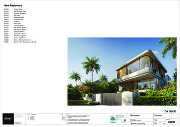
OverviewFront-Panel DescriptionFigure 1-1Cisco IE-3000-8TC Switch120169923451Power and relay connectors410/100 ports2Console port5Protective ground connection3Dual-purpose portsFigure 1-2Cisco IE-3000-4TC Switch12201700Chapter 13451Power and relay connectors410/100 ports2Console port5Protective ground connection3Dual-purpose portsCisco IE 3000 Switch Hardware Installation Guide1-3
Chapter 1Front-Panel DescriptionCisco IEM-3000-8TM Expansion Module201702Figure 1-31110/100 portsCisco IEM-3000-8FM Expansion Module201701Figure 1-411100BASE-FX portsCisco IE 3000 Switch Hardware Installation Guide1-4Overview
OverviewFront-Panel DescriptionFigure 1-5Cisco IEM-3000-4SM Expansion Module123345668411100BASE-X SFP portsFigure 1-6Cisco IEM-3000-8SM Expansion Module15263748345667Chapter 111100BASE-X SFP portsCisco IE 3000 Switch Hardware Installation Guide1-5
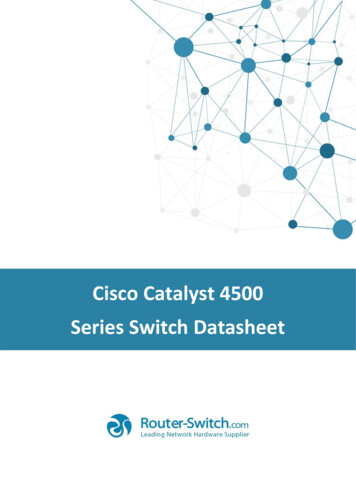
Chapter 1Front-Panel DescriptionFigure 1-7Cisco IEM-3000-4PC PoE Expansion Module1346705231DC Input terminal block2POE STATUS LEDCisco IE 3000 Switch Hardware Installation Guide1-63PoE portsOverview
OverviewFront-Panel DescriptionFigure 1-8Cisco IEM-3000-4PC-4TC PoE Expansion Module123346704Chapter 14110/100 Non-PoE ports3POE STATUS LED2DC-Input terminal block4PoE portsCisco IE 3000 Switch Hardware Installation Guide1-7
Chapter 1OverviewFront-Panel Description10/100 PortsYou can set the 10/100 ports to operate at 10 or 100 Mb/s in full-duplex or half-duplex mode. You canalso set these ports for speed and duplex autonegotiation in compliance with IEEE 802.3AB. (Thedefault setting is autonegotiate.) When set for autonegotiation, the port senses the speed and duplexsettings of the attached device and advertises its own capabilities. If the connected device also supportsautonegotiation, the switch port negotiates the best connection (that is, the fastest line speed that bothdevices support and full-duplex transmission if the attached device supports it) and configures itselfaccordingly. In all cases, the attached device must be within 328 feet (100 meters). 100BASE-TX trafficrequires Category 5 cable. 10BASE-T traffic can use Category 3 or Category 4 cables.When connecting the switch to workstations, servers, routers, and Cisco IP Phones, be sure that the cableis a straight-through cable.For copper ports, you can use the mdix auto interface configuration command in the command-lineinterface (CLI) to enable the automatic medium-dependent interface crossover (auto-MDIX) feature.When the auto-MDIX feature is enabled, the switch detects the required cable type for copper Ethernetconnections and configures the interfaces accordingly. For configuration information for this feature, seethe switch software configuration guide or the switch command reference.Dual-Purpose PortsA dual-purpose port can be configured as either a 10/100/1000 port or as an SFP module port. Only oneport can be active at a time. If both ports are connected, the SFP module port has priority.You can set the 10/100/1000 ports to operate at 10, 100, or 1000 Mb/s in full-duplex or half-duplexmode. You can configure them as fixed 10, 100, or 1000 Mb/s (Gigabit) Ethernet ports and can configurethe duplex setting. (See the switch software configuration for more information.)You can use Gigabit Ethernet SFP modules to establish fiber-optic connections to other switches. Thesetransceiver modules are field-replaceable, providing the uplink interfaces when inserted in an SFPmodule slot. You use fiber-optic cables with LC connectors to connect to a fiber-optic SFP module.For more information about these SFP modules, see the “SFP Modules” section on page 1-8, your SFPmodule documentation or the release note for your switch software.SFP ModulesThe switch Ethernet SFP modules provide connections to other devices. These field-replaceabletransceiver modules provide the uplink interfaces.The modules have LC connectors for fiber-opticconnections or RJ-45 connectors for copper connections. You can use any combination of the supportedSFP modules listed in Table 1-2.Cisco IE 3000 Switch Hardware Installation Guide1-8
Chapter 1OverviewFront-Panel DescriptionTable 1-2Maximum Operating TemperatureType of SFP ModuleRugged and Industrial SFPs–40 to 140 F (–40 to 60 C)Commercial SFPs32 to 113 F (0 to 45 C)Extended temperature SFPs23 to 140 F (–5 to 60 C)Model GLC-SX-MM-RGD GLC-LX-SM-RGD GLC-FE-100LX-RGD GLC-FE-100FX-RGD GLC-ZX-SM-RGD GLC-BX40-D-I with digital optical monitoring(DOM) support GLC-BX40-DA-I with DOM support GLC-BX80-D-I with DOM support GLC-BX40-U-I with DOM support GLC-BX80-U-I with DOM support GLC-BX-D with DOM support GLC-BX-U with DOM support GLC-FE-100LX GLC-FE-100BX-D GLC-FE-100BX-U GLC-FE-100FX GLC-FE-100EX GLC-FE-100ZX CWDM SFP with DOM support DWDM SFP with DOM support GLC-T SFP-GE-L with DOM support SFP-GE-S with DOM support SFP-GE-Z with DOM support GLC-SX-MMD with DOM support GLC-EX-SMD with DOM support GLC-LH-MMD with DOM support GLC-ZX-SMD with DOM supportFor the most up-to-date list of supported SFP models for Cisco Industrial Ethernet switches, seehttp://www.cisco.com/en/US/docs/interfaces modules/transceiver or information about SFP modules, see your SFP module documentation and the “Installing andRemoving SFP Transceivers” section on page 2-41. For cable specifications, see Appendix C, “Cableand Connectors.”Cisco IE 3000 Switch Hardware Installation Guide1-9
Chapter 1OverviewFront-Panel Description100BASE-FX PortsThe IEEE 802.3u 100BASE-FX ports provide full-duplex 100 Mb/s connectivity over multimode fiber(MMF) cables. These ports use a small-form-factor fixed (SFF) fiber-optic transceiver module thataccepts a dual LC connector. The cable can be up to 1.24 miles (2 km) in length.100BASE-X PortsThe IEEE 802.3u 100BASE-X ports provide full-duplex 100 Mb/s connectivity over both single-mode(SMF) and multimode fiber (MMF) cables. These ports use a small-form-factor pluggable (SFP)fiber-optic transceiver module that accepts a dual LC connector (except in the case of theGLC-FE-100BX-U and GLC-FE-100BX-D SFP transceivers). With the GLC-FE-100ZX SFPtransceiver installed, cable runs of up to 49.6 miles (80 km) are supported.PoE PortsThe IEM-3000-4PC and the IEM-3000-4PC-4TC expansion modules provide 10/100BASE-T PoEcapability to the IE3000 base switch. Both expansion modules support up to 4 PoE (802.3af) or 4 PoE (802.3at) devices. The PoE expansion modules require a dedicated power supply for PoE power.Power and Relay ConnectorYou connect the DC power and alarm signals to the switch through two front panel connectors. Oneconnector provides primary DC power (supply A) and the major alarm signal, and a second connector(supply B) provides secondary power and the minor alarm signal. The two connectors are physicallyidentical and are in the upper left side of the front panel. See Figure 1-2.The switch accessory pack includes the mating power and relay connectors. These connectors providescrew terminals for terminating the DC power and alarm wire and the connector plugs into the powerand relay receptacles on the front panel. The positive DC power connection is labeled V, and the returnconnection is labeled RT (see Figure 1-9).Figure 1-9Power and Relay Connector201815V RTA AThe switch can operate with a single power source or with dual power sources. When both power sourcesare operational, the switch draws power from the DC source with the higher voltage. If one of the twopower sources fail, the other continues to power the switch.The power and relay connectors also provide an interface for two independent alarm relays: the majorand the minor alarms. The relays can be activated for environmental, power supply, and port status alarmconditions and can be configured to indicate an alarm with either open or closed contacts. The relay itselfis normally open, so under power failure conditions, the contacts are open. From the CLI, you canassociate any alarm condition with one or with both alarm relays.Cisco IE 3000 Switch Hardware Installation Guide1-10
Chapter 1OverviewFront-Panel DescriptionAlarm relays often control an external alarm device, such as a bell or a light. To connect an externalalarm device to the relay, you must connect two relay contact wires to complete an electrical circuit. Bothalarm terminals on the power and relay connector are labeled A, and you can connect them withoutregard to polarity.See the switch software configuration guide for instructions on configuring the alarm relays.For more information about the power and relay connector, see Appendix C, “Cable and Connectors.”You can get replacement power and relay connectors (PWR-IE3000-CNCT ) by calling Cisco TechnicalSupport.Console PortYou can connect a switch to a PC through the console port and the supplied RJ-45-to-DB-9 adapter cable.If you want to connect a switch to a terminal, you need to provide an RJ-45-to-DB-25 female DTEadapter. You can order a kit (part number ACS-DSBUASYN ) with that adapter from Cisco Systems.For console-port and adapter-pinout information, see the “Two Twisted-Pair Cable Pinouts” section onpage C-8.LEDsYou can use the LEDs to monitor the switch status, activity, and performance. Figure 1-10 to Figure 1-13show the front panel LEDs, and the following sections describe them.All LEDs are visible through the GUI management applications—the Cisco Network Assistantapplication for multiple switches and the device manager GUI for a single switch. The switch softwareconfiguration guide describes how to use the CLI to configure and to monitor individual switches andswitch clusters.Cisco IE 3000 Switch Hardware Installation Guide1-11
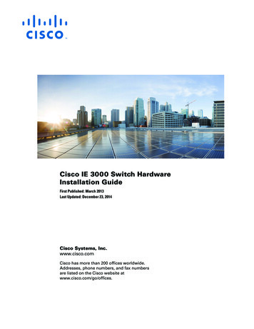
Chapter 1OverviewFront-Panel DescriptionFigure 1-10LEDs on the Cisco IE 3000 Switch1236781Express setup button5Dual-purpose uplink port LED2System LED6Pwr B LED3Alarm LED7Pwr A LED4Setup LED8Port LEDFigure 1-11LEDs on the Cisco IEM-3000-8TM Module1110/100 port LEDCisco IE 3000 Switch Hardware Installation Guide1-1220170652017034
OverviewFront-Panel DescriptionLEDs on the Cisco IEM-3000-8FM Module201705Figure 1-1211100BAS
Contents iii Cisco IE 3000 Switch Hardware Installation Guide Connecting to SFP Transceivers 2-44 Connecting to a Dual-Purpose Port 2-45 Connecting to 100BASE-FX Ports 2-47 Connecting to a PoE Port 2-48 Connecting the Switch to the Power Converter 2-48 Attaching the Power Converter to the Switch 2-49 Installing the Power Converter on a DIN Rail, Wall, or Rack Adapter 2-50