Transcription
1GE Consumer & IndustrialElectrical DistributionApplications / SpecificationsDET-456Power/Vac Metal-Clad Switchgearand Vacuum Circuit BreakersMaintenance andTroubleshootingSuggestions
2POWER/VAC MAINTENANCE AND TROUBLESHOOTINGSUGGESTIONSINTRODUCTIONObserving the following practices will save time, effort and frustration, as well asprevent possible damage to equipment and injury to personnel.A regular maintenance schedule should be established to obtain the best service andreliability from the switchgear. Plant operation and local conditions will dictate thefrequency of inspection required. It is the GE recommendation that, until the user hasaccumulated enough experience to select a test interval better suited to the individualrequirements, all significant calibrations be checked at an interval of one to two years,or 2000 operations whichever occurs first. If the service conditions are mild, the intervalbetween maintenance operations may be extended to 10 years. Mild service conditionsare defined by ANSI as an environment in which the switchgear is protected from thedeleterious effects of conditions such as:Salt atmosphereChanges in temperature that produce condensationConductive and/or abrasive dustDamaging chemicals and fumesVibration or mechanical shockHigh relative humidity ( 90%)Temperature extremes ( -30 C or 40 C)For specific information regarding the maintenance of devices, such as molded casebreakers, relays, meters, etc., refer to the separate instruction book furnished for eachdevice. The breaker test cabinet, when furnished, provides a convenient means formaintaining Power/VAC circuit breakers. Under normal conditions, the protective relaysdo not operate except on a fault, therefore, it is important to check the operation ofthese devices regularly.A permanent record of all maintenance work should be kept, the degree of detaildepending on the operation conditions. In any event, it will be a valuable reference forsubsequent maintenance work and for station operation. It is recommended that therecord include reports of tests made, the condition of equipment and repairs andadjustments that were made.CAUTION: Before any covers are removed or any doors opened whichpermit access to the primary circuits, it is essential that the circuit orcircuits be de-energized and breakers be withdrawn to the test position andtagged.The primary circuits of metalclad switchgear are insulated in order to reduce the size ofthe equipment. However this insulation, except in one or two instances, requires acertain amount of air gap between phases and to ground to complete the insulationsystem. Inserting any object in this air space when equipment is energized, whether itbe a tool or part of the body, may under certain conditions, in effect short circuit this airgap, and may cause a dielectric breakdown in the primary circuit to ground and causeserious damage or injury or both.
3Care should be exercised in the maintenance and checking procedures such thataccidental tripping or operation is not initiated.
4SPECIFICThe following items or tasks should always be referred to in the instruction book:1. Breaker maintenance recommended intervals.2. Recommended intervals of equipment maintenance.3. Slow-closing procedures.4. Mechanical adjustments.5. Lubrication recommendation.6. Repair and replacement procedures.7. Ordering instructions for renewal parts.GENERAL1.The term "front" of the equipment means facing the breaker door.2.The terms " left" and "right" side of the equipment refer to a person facing thefront of the equipment.3.Be aware of your limitations. Learn all you can about the equipment operationbefore you begin to service it.4.Set up a clean, clear area in which to work.5.Completely read each procedure while looking at the actual parts beforebeginning. Thoroughly understand what is to be done and follow theprocedure step by step.6.Use a systematic approach.7.Do not panic; take a calm and methodical approach.8.Take precautions and observe safety procedures before servicing thebreaker or equipment. Consult NFPA 70B and 70E.9.Protect finished surfaces from physical damage or corrosion.10. Use proper tools for each job.
511. Never disassemble more than is required.12. Parts sequence is important, keep track of parts, place bolts and screws inenvelopes and label them. It is also a good practice to re-install bolts andscrews after removing the part which they held.13. No parts, except those assembled with a press fit, require unusual force duringassembly. If a part is hard to remove or install, find out why before proceeding.14. Soaking with penetrating oil can often loosen frozen or very tight bolts andscrews. Avoid heat, since it may melt, warp or remove the temper from manyparts.15. When assembling components, start all fasteners evenly.16. When you need help, refer matters to the GE Resolve help line, 1-888-4373765.
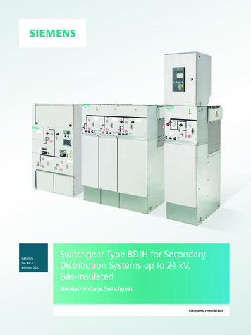
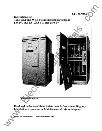
6NOMENCLATURE FOR TROUBLE-SHOOTING GUIDESPOWER/VAC ML-17 & ML-18 OPERATINGMECHANISMSNOMENCLATUREThe following list defines the purpose of the various devices (i.e., switches, relays, etc.)that are associated with the electrical aspect of the ML-17/17H and ML-18/18Hoperating mechanisms. These mechanisms are the stored energy forms that are usedon GE Type VB, VBH, VB1 and VB1H Vacuum Circuit Breakers.Reference should be made to the specific electrical schematic and connection diagramreferenced on the breaker nameplate, to determine the electrical relationship betweenthe various devices. Standard ML-17 (Fig. 1) and ML-18 (Fig. 2) mechanismconnection diagrams are included at the end of this guide, and are drawn with thebreaker in the open and discharged state.The descriptions to follow are the basic functions of the various devices. Once a personis able to understand how the mechanical and electrical aspects function separately,realization of how the two function together should follow easily. The two aspects arenot independent. If the mechanical aspect does not function properly, the mechanismwill not function electrically. The reverse is not true. The mechanism could functionmechanically but not electrically.52MOTOR SPRING CHARGING MOTORThe motor is used to charge the breaker closing springs.52CL/MS CLOSING LATCH MONITOR SWITCHThis contact is used to prevent charging the closing springs until the closing latch isproperly reset. Switch contacts are held open between disconnect and connect positionswhen the breaker is inserted or withdrawn from an enclosure.52SM/LS SPRING MOTOR LIMIT SWITCHThere are two contacts on this switch: both contacts are open when closing springs arecharged.Contacts 1 & 2: This contact removes power from the charging motor when the springsare charged.Contacts 3 & 4: This contact picks up the 52Y relay when the springs discharge toengage the anti-pump feature.
752IL/MS NEGATIVE INTERLOCK MONITOR SWITCHThis contact is used to block the charging circuit while the racking crank is engaged. Thisswitch is present on ML-18/18H mechanisms produced after 2002. Reference internaldiagram 0209B8267.52CHG CHARGE SWITCHThese contacts monitor the closing spring positions. Contacts are closed when closingsprings are fully charged and the contacts are in parallel to withstand the current surgeof the closing.52XCLOSING COIL (ML-17/17H), or 52 (ON ML-18/18H)CCThis device is a solenoid, which electrically releases the closing latch to allow closingsprings to discharge, closing the breaker. This coil is rated as a momentary coil.52YANTI-PUMP RELAYThe contacts of this relay prevent uncontrolled discharging of the closing spring, if theclosing signal remains complete up to the breaker. If the circuit remains complete, theclosing spring would discharge under the wrong conditions, this is called pumping.Therefore the anti-pump relay prevents the spring from doing the following:A.Re-closing the breaker after the breaker has opened.B.Closing the breaker automatically when the closing spring initially chargesafter the breaker is inserted.C.Cycling the closing spring from charged to discharged to charged and so onuntil the charging motor fails (motor is not rated for continuous duty).(ML-17/17H) Contacts 7 & 3 and 4 & 8 or (ML-18/18H) Contacts 7 & 1 and 3 & 9:These contacts are used to break open the closing circuit when the external closesignal is removed.(ML-17/17H) Contact 1 & 7 or (ML-18/18H) Contact 4 & 7: This contact “seals in”(keeps energized) the 52 relay until the external portion of the closing circuit opens.52TC TRIP COILThis device is a solenoid that lifts the trip latch thus allowing the breaker to open. This coilis rated as a momentary coil.
8AUXILIARY SWITCHThe contacts of the auxiliary switch provide an indication in the control circuit of whether thepower circuit (main) contacts are either open or closed. They also de-energize the closingcoil and the trip coil.(ML-17/17H) Contact 1 & 1C or (ML-18/18H) 1 & 2: This contact de-energizes theclosing coil, and also prevents electrically discharging of the closing spring of aclosed breaker.(ML-17/17H) Contact 2 & 2C and 4 & 4C or (ML-18/18H) Contacts 3 & 4 and 7 &8: These contacts are used to de-energize the trip coil after the breaker hasopened.All Other Contacts: These contacts are used in the control circuits as needed forcontrol, indication, transferring and interlocking.TROUBLE-SHOOTING GUIDESEach of the four guides is based upon certain conditions having taken place.FAILS TO CHARGE: means the closing springs will not compress to chargedposition. This condition can happen after the breaker has been placed in thetested or connected position, or after the breaker has been closed electrically ormanually.FAILS TO CLOSE: means there has been no discharge of the closing springs,which is what mechanically closes the main contacts.FAILS TO TRIP: means the breaker is closed and will not open.TRIP-FREE: means when the breaker is given an electrical or manual closingcommand, the closing springs discharge but the mechanism (i.e. main contacts)will not latch closed. The contacts return to an open position.
9SWITCHGEAR INTERLOCKS AND SAFETYFEATURESINTRODUCTIONInterlocks and safety features on switchgear are for the purpose of protecting bothoperating personnel and the equipment from physical harm. It is therefore, important toremember that an INTERLOCK or SAFETY FEATURE should never be bypassed ofdefeated.The various mechanical and electrical interlocks and safety features to be describedbelow will be described literally not physically. To determine the physical description,the appropriate instruction book should be referenced. The described list can be foundin part or in total on various types of switchgear. To determine which of these featuresare associated with a piece of equipment, the operating instruction of that equipmentshould be referenced.MECHANICALPOSITIVE INTERLOCKThis interlock mechanically couples the breaker so that the racking mechanism can onlybe engaged if the breaker is in the OPEN position. This interlock prevents inserting orremoving a closed breaker.NEGATIVE INTERLOCKThis interlock mechanically places the breaker's trip shaft in a tripped position, and thusprevents closing a breaker in any position other than TEST or CONNECTED after theracking mechanism has been disengaged.SPRING DISCHARGE INTERLOCKThis interlock will discharge the closing springs to provide a mechanical safety featureso that a breaker is DISCHARGED as well as open when it is removed from theequipment. GE PowerVAC switchgear is designed to discharge the springs anytime thebreaker is moved from one position to another for enhanced safety.PADLOCKSProvisions are provided on either the breaker or the racking mechanism to enable thebreaker to be locked out during certain operations or maintenance. The padlockingcan either prevent closing the breaker and/or prevent engaging the rackingmechanism.KEY INTERLOCKINGThis feature allows the coordination between two or more DEVICES so that certainoperations must be performed to one device before proceeding to operate the nextdevice. The above coordination is accomplished by special locks, which hold the keycaptive until the proper conditions are met. When the conditions are met the key can beremoved and inserted into another special lock on another device in order to properlyoperate it.
10SAFETY ROLL-IN STOPRegardless of the position of the racking mechanism, it is impossible to manually insertthe breaker into the rails beyond the disconnect / test position.SAFETY ROLL-OUT STOPThis safety stop prevents the breaker front being rolled out of the equipmentaccidentally. This stop has to be manually released prior to breaker removal onto thetransfer truck.GAG SPRING INTERLOCKWhile the closing spring may have been gagged for breaker adjustments, without thisinterlock it would be possible to put the breaker into operational position. This interlock,therefore, assures that only breakers with freely operating closing springs can beinserted into the equipment.RATING INTERFERENCE INTERLOCKThis is a very sturdy mechanical interlock, which is coded so that only the properly ratedbreaker can be inserted into its designated location.ELECTRICALINTERLOCK SWITCHESThe basic function of these switches is to block electrical closing signals and to open theclosing mechanism's current charging circuit whenever a breaker is being inserted orremoved. Because the electrical switches can be operated by various mechanical partsto do the same job, INTERLOCK SWITCH is a general term. To determine just whichswitch provides the feature, the electrical schematics should be referenced.
11GUIDE 1FAILS TO CHARGENo voltageLow voltage(Test under load)ElectricalLimit switches52 CL/MS & 52 SM/LS & 52 IL/MS** only on ML-18/18H mech’s after 2002Secondary disconnectFusesBroken wiresGrounded wiresPinched wiresLoose connectionsCorroded connectionsImproper adjustmentSwitch failureLoose wiresPoor fitting disconnectLoose / corroded pinsFails to chargeCharging motorMechanicalTerminal blockConnection looseMotor failureCheck for rotation of gearbox outputshaftCheck shear pin at drive shaft junction(ML-17/17H)(Motor runs butdoes not chargespring)If charging wheel turnsCheck charging pawlCheck to see if flywheel assembly hasstopped in properposition (ML-17/17H)Check for proper reset of closing latch ifclose spring immediately discharges atend of charging cycleRack mechanism Breaker not in position properlySliding rail has not reset
12GUIDE 2FAILS TO CLOSENo voltageElectricalFusesBroken wiresGrounded wiresLow voltage(Test under load)Pinched wiresLoose connectionsCorroded connectionsLimit switches52 LCS & 52 CHGImproper adjustmentSwitch failureLoose wiresSecondary disconnectPoor fitLoose / corroded pinsFails ToClose52X open coil (52/CC on ML-18/18H)Auxiliary switchLoose wiresSwitch failureFailure of operatinglinkage52Y (Anti-pump relay)Loose wiresN/O contacts badImproper dropoutTrip latch is not resettingMechanicalCheck to see if breaker is chargedCheck freeness of closing shaftarmature linkageAdjust clearanceNot returning to stop
13GUIDE 3FAILS TO TRIPFusesBroken wiresGrounded wiresNo voltagePinched wiresLoose connectionsCorroded connectionsLow voltage(Test under load)ElectricalTrip coil52/TCOpen coilSecondary disconnectPoor fitLoose / corroded pinsFails to tripLoose wiresSwitch failureSwitch operatingLinkage failureAuxiliary switchMechanicalGUIDE 4Linkage on trip plunger bound upPin missing out of shaft junctionMain contacts welded togetherTRIP FREEMaintained Voltage ontrip circuitElectricalNot resettingTrip freeTrip latchNegative interlock notadjusted properlyMechanicalToggle link not making toggleposition due to bearing wearNo clearanceBroken resetspringShaft bindingLinkagebinding
14BREAKER PREVENTIVE MAINTENANCE CHECK-OFF LISTCOMMENTS1.Check that breaker is open and discharged.2.Record breaker serial number and number ofoperations.3.Inspect for damage to breaker (exterior).4.Perform a visual inspection of the breaker andremove dust and contaminants from theinterrupter housing, insulation, andmechanism. Do not use compressed air.5.Inspect the interrupters and operatingmechanism carefully for loose nuts, bolts anddamaged parts. All cam latch and rollersurfaces should be inspected for damage orexcessive wear.6.Check that the trip coil plunger and close coilplunger move freely.7.Inspect condition of primary and secondarydisconnects.8.Inspect for evidence of overheating ortracking.9.Lubrication9.1 On all sleeve, needle, and roller bearingsapply 2 or 3 drops of Mobile No. 1 oil.9.2 On each silver plated primary disconnectfinger assembly, wipe clean and apply alight coat of GE 0282A2048P009lubricant (red grease).9.3 On the vacuum interrupter connector rod(movable, each pole) apply a light coat of0282A2048P009 lubricant (red grease).10. Operate the breaker slowly to be sure there isno binding or friction and that the movablecontact of the interrupter can move to the fullyopened and fully closed position.
15COMMENTS11. Check interrupter and mechanismadjustments.12. Check contact erosion indicator.13. Inspect transfer finger wear.14. Check all wiring for tightness of connectionsand possible damage to insulation.15. Check primary circuit integrity by means of a2500 volt megohmmeter (breaker in the closedposition phase to phase and phase to ground)16. Check control circuit integrity by means of a500/1000 volt megohmmeter. (Note:Disconnect motor leads to prevent windinginsulation damage.)17. Perform a high potential test (vacuum integritytest) on each vacuum interrupter as describedin instruction book.WARNING: X-Radiation may constitute ahealth hazard. Refer to instruction book forproper procedures.18. Operate the breaker using the test cabinet andobserve the following:18.118.218.318.4Breaker charges properly.Breaker closes and opens correctly.Breaker trips freely.Indicators show correct position.19. Place breaker in the equipment in the testposition and operate it electrically.20. Check the operation of all electrical relays(including protective relay devices), solenoidswitches, motors, control switches, andindicating devices.21. Check negative interlock.22. Check positive interlock.23. Check spring discharge interlock
16SWITCHGEAR EQUIPMENTPREVENTIVE MAINTENANCE CHECK-OFF LISTCOMMENTS1.Disconnect primary power from switchgear.2.Disconnect control power except for Items 9,10, and 19.3.Check exterior of equipment for damage.4.Check equipment ground bus and itsconnection(s) to station ground.5.On outdoor switchgear, check integrity of sealagainst weather and rodents.6.Check doors for damage.7.Check door handles, locking bars, keys andinterlocks for positive operation.8.Insure structure is tight.9.Check cabinet lighting (if present).10. Check heaters and heater circuits (if present).11. Check that all power and control cableentrances are sealed against rodents and firecontaminants.12. Check all wiring connections, including thoseon terminal blocks.13. Check draw-out racking mechanisms (alsocheck lubrication).14. Check shutter mechanism.
17COMMENTS15. Inspect bus and support insulators forevidence of corona or insulation deterioration16. Megohmmeter test switchgearlightning arresters (if present).17. Check control knobs and switches for freedomof movement and contact condition.18. Check mechanical and electrical integrity of allrelays19. Perform sequencing check ofprotective, auxiliary, and controlrelays.20. Inspect switchgear instruments(meters, switches, and indicatinglights).21. Inspect all instrument transformers.22. Inspect all fuses.23. Inspect and check batteries and batterycharging equipment (perform a load test).24. Clean all compartments and bus sections.25. Lubricate racking mechanism, if not doneunder Item 13.26. Check to insure that all key interlocks areoperational and no spare keys are used.
18BREAKER MAINTENANCE TOOL LISTThe following common tools are recommended for proper maintenance of thebreaker (NOTE: Obtain from local hardware supplies; do not order from GeneralElectric Company.)Socket Wrenches (1/2" drive)Ratchet Handle10" Extension Bar4" Extension Bar7/16" Socket9/16" Socket5/8" Socket3/4" SocketInstrumentsSimpson Multi-Meter or similarInsulation TesterVacuum Integrity TesterHand WrenchesAdjustable 10"7/16” Open End9/16" Open End15/16" Open End1 1/16" Open End1 1/8" Open EndScrew DriversLong Thin Slotted ScrewStandard Slotted ScrewMiscellaneous ToolsHammer or MalletMicrometerFlashlightTorque Wrench 0-60 Ft. Lbs.Feeler GagesInspection MirrorRuler "Accurate" 6" LongCalipersDepth MicrometerAllen Head Wrenches3/16"1/4"PliersLong Nose 6"Wire CuttersWire StrippersStakon PliersSlip-joint Pliers 8"
19POWER/VAC INSULATION TESTSFIELD INSTRUCTIONSI.MEGGERPrimary CircuitThe primary circuit insulation on the equipment and the breaker may bechecked phase-to-phase and phase-to-ground using a 2500V megohmmeter.Secondary CircuitPrior to meggering the equipment secondary circuit, remove all circuit grounds,thread a wire throughout the equipment which will connect all devices and theirterminals together.Prior to meggering the breaker secondary circuit, remove the motor leads,thread a wire connecting all secondary disconnect pins together except for pin#24 which is the ground pin.The breaker and the equipment may be meggered by connecting a 500Vmegohmmeter from the wire to ground.Since definite limits cannot be given for satisfactory insulation values, a recordshould be kept of the megger readings as well as temperature and humidityreadings. This record would be used to detect any weakening of the insulationfrom one check period to the next.II.HIGH POTENTIAL TESTHigh potential tests to check the integrity of the insulation are not necessary atstart-up.Should high potential tests be required, the AC high p o t e n t i a l test described isstrongly recommended by the GE Switchgear Business. DC high potentialtesting of the bus or equipment is not recommended, except for theVacuum Interrupter Integrity Test.If DC high potential cable testing is required, the DC high potentialmachine must not produce peak voltages that exceed 50 kV, and thefollowing procedure must be adhered to:1. The calibration of the DC test set has been checked to read peak voltagescorrectly at the peak test level noted in Table 1.2. That all voltage sensitive devices are removed or disconnected prior to test(i.e. surge arrestors, surge capacitors, VT’s, CPT’s). The breaker associatedwith the cables to be tested should be in the disconnected position, and anyrollout trays withdrawn. All insulators to be energized should be clean anddry.3. Voltages should be increased and decreased slowly (2 kV per secondmaximum).4. Peak DC voltage does not exceed peak test level noted in Table 1.
20After reassembly of components, all disturbed wiring and insulation systems should berestored to original conditions and inspected. Some integrity test for dielectric capabilityis recommended – at least a megger test.Primary CircuitPrior to high potential testing of the equipment primary circuit, the potentialtransformers; control power transformers, lightning arresters, surgesuppressors, and breakers must be electrically disconnected from theequipment.The breaker should be hi-potted in the closed breaker mode.An AC hi-pot machine capable of producing the voltages shown in Table 1 ofthis instruction may be used to hi-pot the equipment and breaker phase-tophase and phase-to-ground.The machine should be connected with its output potential at zero, the voltagecan then be increased to the voltage shown in Table 1 and that voltagemaintained for 60 seconds. DC high potential tests voltages from Table 1 are tobe maintained for 15-30 seconds and are not to exceed 30 seconds. The voltageshould then be returned to zero, and the hi-pot machine removed from the circuit.(NOTE: Voltages shown in Table 1 should not be exceeded).Secondary CircuitPrior to hi-potting the equipment secondary circuit, remove all circuit grounds.Thread a wire throughout the equipment, which will connect all devices and theirterminals together. Short out all meter, relay or other coils so that a possibleground will not draw damaging current through such coils. Isolate all GE andother vendors “non-hi-pot” devices, small commutator-type motors or any otherapparatus of unknown hi-pot value. Remove all known ground connections.Prior to hi-potting the breaker secondary circuit, remove the motor leads,thread a wire connecting all secondary disconnect pins together except for pin#24 which is the ground pin.The breaker and the equipment may be hi-potted by connecting the hi-potmachine from this wire to ground with the output voltage at zero. The voltagecan then be increased to 1125 volts (rms) 60 Hz. and maintained for 60seconds. (1600 volts DC maintained for 15-30 seconds not to exceed 30seconds). Reduce the voltage to zero and remove the high potential machinefrom the circuit.NOTE: After removing high potential machine, return equipment and breaker tooriginal state.EquipmentVoltageTABLE 1*Test Voltages60 Hz (rms)DC
214.167.213.814 kV27 kV27 kV20 kV38 kV38 kV*The AC voltages are 75% of factory test voltages in accordance with ANSIstandards.
22III.VACUUM INTERRUPTER INTEGRITY TESTThis test of the vacuum interrupter will determine its internal dielectric conditionand vacuum integrity. Prior to performing any vacuum interrupter integrity tests,the outside (external surface) of the interrupter should be wiped clean of anycontaminates with a non-linting cloth. This is critical that the entire externalsurface is to be completely free of all dirt, dust, oil, etc. With the breaker open,individually check each interrupter by connecting the hi-pot machine across theprimary studs (bars) on the breaker side of the disconnect fingers. Ground theother two interrupters line and load side of the primary studs, the frame, and thesecondary wiring. Increase the hi-pot machine voltage to 36kV (rms) 60 Hz. andmaintain for 60 seconds. If no breakdowns occur during any of the three hi-pottests, the interrupters have passed and the breaker can be put into service. If abreakdown occurs in an interrupter, it must be replaced.GE Burlington continues to strongly recommend the use of an AC highpotential machine for vacuum interrupter integrity tests. DC testing of vacuuminterrupters should only be utilized if an AC tester is not available, and should beused for quick field checks only. Our experience with DC testers over manyyears indicates they frequently yield false negative test results, due partially tothe capacitive component of the vacuum interrupter during DC testing, and tothe fact that most lightweight DC testers have a very low leakage current tripsetting. They will however, reliably indicate a truly failed bottle if the voltageoutput is set at 50kV DC.If using a DC tester, and a test indicates a bad interrupter, retest with the polarityof the DC test voltage reversed. If this results again in a failure, we wouldrecommend a final AC test prior to contacting GE Post Sales Service ordiscarding the interrupter.No attempt should be made to try and compare the condition of one vacuuminterrupter with another, or to correlate the condition of any interrupter to lowvalues of DC leakage current. There is no significant correlation.After the high potential voltage is removed, discharge any electrical chargethat may be retained.CAUTION: MANY OLDER DC HIGH POTENTIAL MACHINES ARE HALFWAVE RECTIFIERS. THIS TYPE OF HI-POT TESTER MUST NOT BE USEDTO TEST VACUUM INTERRUPTERS. THE CAPACITANCE OF THEPOWER/VAC BOTTLE IS VERY LOW AND THE LEAKAGE IN THE RECTIFIERAND ITS DC VOLTAGE MEASURING EQUIPMENT IS SUCH THAT THEPULSE FROM THE HALF-WAVE RECTIFIER MAY ACTUALLY BE IN THENEIGHBORHOOD OF 120KV, WHEN THE METER IS ONLY READING 40KV.IN THIS CASE, SOME PERFECTLY GOOD BOTTLES CAN SHOW ARELATIVELY HIGH LEAKAGE CURRENT SINCE IT IS THE PEAK VOLTAGEOF 120KV THAT IS PRODUCING ERRONEOUS BOTTLE LEAKAGECURRENT. IN ADDITION, THE X - RADIATION WILL BE OF CONCERN.
23An acceptable AC high potential test machine is available from the GE ElectricalEquipment Business, Burlington, Iowa, catalog number 282A2610P001.Other acceptable manufacturers of portable AC and DC insulation testersinclude Hipotronics models numbers 7BT60A, 60HVT, 860PL (DC) and880PL (DC), or GE/Programma model VIDAR (DC).MECHANISM ADJUSTMENTSAdjustments are set at the factory and will seldom require more than a quickcheck. Mechanism life testing has proven that normal wear is negligible and onlysevere contact erosion may require readjustment. Major repairs such as replacinginterrupters may also require some readjustment. Refer to the specific breakerinstruction book for the mechanism type being used. For ML-18/18H seeInstruction Book GEK-86132G, and for ML-17/17H see Instruction Book GEK39671F & supplement DET-002.
24Fig. 1 Typical Wiring Diagram for ML-17/17H Mechanism
25Fig. 2 Typical Wiring Diagram for ML-18 Mechanism
26These instructions do not purport to cover all detailsor variations in equipment or to provide for everypossible contingency to be met in connection withinstallation, operation or maintenance. Should furtherinformation be desired or should particular problemsarise which are not covered sufficiently for thepurchaser’s purposes, the matter should be referredto the General Electric Company.GE Consumer & IndustrialElectrical DistributionSwitchgear Business510 East Agency RoadWest Burlington, Iowa 526558 2005 General Electric Companywww.geelectrical.comDET-456
POWER/VAC ML-17 & ML-18 OPERATING MECHANISMS . of the ML-17/17H and ML-18/18H operating mechanisms. These mechanisms are the stored energy forms that are used on GE Type VB, VBH, VB1 and VB1H Vacuum Circuit Breakers. . means when the breaker is given an electrical or manual closing command, the closing springs discharge but the mechanism (i .