Transcription
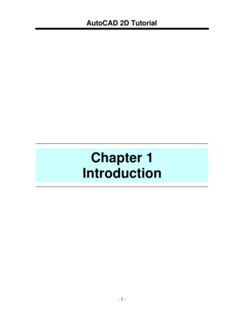
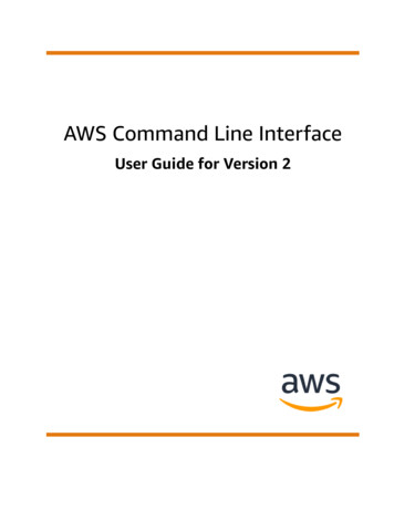
AN678P RECISION 3 2 SI 32F LASH U T I L I T Y C OMMAND - L INEP ROGRAMMER U SER ’ S G U ID E1. IntroductionThe Precision32 si32FlashUtility Command-Line Programmer is a simple program to enable productionprogramming capability using the Silicon Labs 32-bit USB Debug Adapter. This utility can also program and eraselock bytes.Figure 1 shows an invocation of the command-line utility.Figure 1. Precision32 si32FlashUtility Command-Line Programmer2. Relevant DocumentationPrecision32 Application Notes are listed on the following website: www.silabs.com/32bit-appnotes. AN667: AN669:Rev. 0.1 3/12Getting Started with the Silicon Labs Precision32 IDEIntegrating Silicon Labs SiM3xxxx Devices into the Keil µVision IDECopyright 2012 by Silicon LaboratoriesAN678
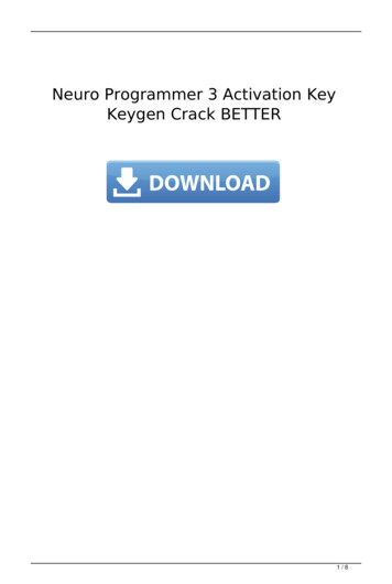
AN6783. Programming OptionsThe si32FlashUtlility has a command-line form of:si32FlashUtility [-options] [drive:][path]imageThese options consist of the following: -v:Verify the image after downloading to Flash.Display additional information during the programming process (i.e., verbose mode). -e {0,1,2}: Erase Flash with three mode options. -p {0,1,2}: Debug port selection with three mode options. -r {0,1,2}: Reset during programming with three mode options. -l: List the available USB Debug Adapters (UDAs). -s SERIAL: Specify the USB Debug Adapter serial string.This section discusses each of these programming options in more detail. -i:3.1. Download VerificationUsing the -v option flag causes the si32FlashUtility to verify the Flash contents after the download. The commandline utility will output a Download complete and verified message if the Flash contents match the HEX image.3.2. Verbose FeedbackWith the -i option flag, the si32FlashUtility programmer will report feedback about each step of the programmingprocess, as shown in Figure 2.Figure 2. Verbose Mode Output2Rev. 0.1
AN6783.3. Flash EraseThe -e option flag has three modes: merge, sector, and full. The default option is sector (-e 1) if no option isspecified.The merge option is selected with -e 0 and causes the programmer to read the current contents of the Flash pageselected by the HEX file address, copy any contents that are not written in the HEX image, erase the page, andwrite the merged image back to Flash. This option allows developers to maintain any calibration or code constantsin Flash when updating code.When using the -e 1 sector erase option, the programmer will first erase the page selected by the HEX imageaddress before programming the contents of the HEX image.The final option, -e 2, causes the programmer to erase the entire Flash before programming the HEX image.3.4. Debug PortThis option selects the debug port of the device. The -p 0 selection is for any devices with JTAG debug pins. The-p 1 option is for devices with Serial Wire debug pins only (SW-DP). The -p 2 option uses the Serial Wire protocoland is for devices with both JTAG and Serial Wire debug pins (SWJ-DP), like the SiM3U1xx device family. Thedefault option is -p 2 if no option is specified.The JTAG selection (-p 0) does not have provisions for JTAG chaining.3.5. Reset OptionsThe utility supports three different reset options: none, before, and during. The default option is none (-r 0) if nooption is specified.The none option (-r 0) prevents the utility from toggling the reset pin at any point during the programming process.The before option (-r 1) allows the si32FlashUtility to toggle reset immediately before programming. This option isuseful for SiM3U1xx or SiM3C1xx devices that may be unresponsive due to switching to a non-existent clock.Using this option along with the recommended reset delay in the startup code ensures the USB Debug Adapter willbe able to communicate with the device.For the during option (-r 2), the utility asserts the reset pin while attempting to halt the core. Once the core is halted,the utility deasserts the reset pin and starts programming. This option ensures the Debug Adapter can alwayscommunicate with a device without the reset delay in the startup code for devices that support this feature.Note: The -r 2 option is unavailable for SiM3U1xx and SiM3C1xx devices.3.6. USB Debug Adapter OptionsThe -l option flag lists the available USB Debug Adapters connected to the PC or system. The -s SERIAL optionflag can then specify the USB Debug Adapter the utility should use for programming.Rev. 0.13
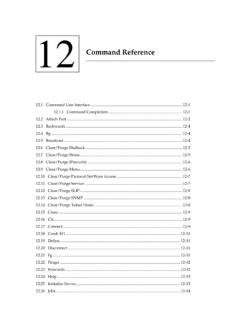
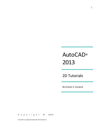
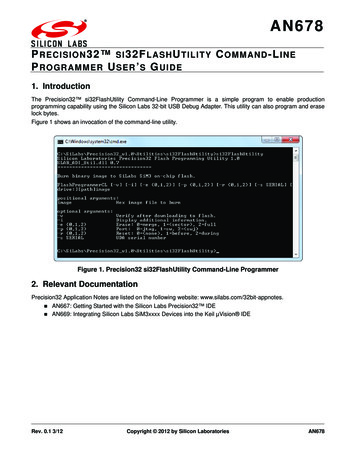
AN6784. Creating HEX Files with the Precision32 IDEThe si32FlashUtility programmer expects HEX files as its input, and the Precision32 IDE includes a utility that canconvert the GCC AXF file output to HEX files. This objcopy utility can be found in the.\Precision32 vx.y\IDE\precision32\Tools\arm-none-eabi\bin path after installing the Precision32 softwarepackage from www.silabs.com/32bit-software.More information on the usage of this utility can be found on the CodeRed website: Formats.4.1. Using the Objcopy Utility from the IDETo use the objcopy utility from the IDE:1. Hold the Ctrl button and left-click on the project name in the IDE footer as shown in Figure 3. This willopen a command prompt in the project directory with the proper paths to use the utility.Figure 3. Opening a Project Command Prompt2. Type cd build directory, where build directory is Debug by default.3. Invoke the utility: arm-none-eabi-objcopy -O ihex project name.axf project name.hex. In the case ofthis example, which uses the sim3u1xx Blinky project: arm-none-eabi-objcopy -O ihexsim3u1xx Blinky.axf sim3u1xx Blinky.hex.4Rev. 0.1
AN678Figure 4. Invoking the Objcopy Utility4.2. Setting the IDE Project to Automatically Generate a HEX FileTo configure the Precision32 IDE project to automatically generate a HEX file after a build:1. Right-click on the project name in the Project Explorer view.2. Select Properties.3. In the C/C Build Settings Build Steps tab, type the following in the Post-build steps Commandbox: arm-none-eabi-objcopy -O ihex {BuildArtifactFileName} {BuildArtifactFileBaseName}.hexFigure 5. Automatically Generating a HEX File on Project BuildRev. 0.15
AN6785. ExamplesTo verify the download of the sim3u1xx Blinky.hex file:si32FlashUtility -v sim3u1xx Blinky.hexThis example is shown in Figure 6.Figure 6. Example with Flash VerificationTo verify the download of the sim3u1xx Blinky.hex file, use verbose mode, erase the device before the download,and reset before:si32FlashUtility -v -i -e 2 -r 1 sim3u1xx Blinky.hexFigure 7 shows an example of this call to the si32FlashUtility programmer.Figure 7. Example with Flash Verification, Verbose Mode, Full Device Erase, and Reset BeforeOptions6Rev. 0.1
Simplicity StudioOne-click access to MCU andwireless tools, documentation,software, source code libraries &more. Available for Windows,Mac and Linux!IoT plicityQualitywww.silabs.com/qualitySupport and Communitycommunity.silabs.comDisclaimerSilicon Labs intends to provide customers with the latest, accurate, and in-depth documentation of all peripherals and modules available for system and software implementers using orintending to use the Silicon Labs products. Characterization data, available modules and peripherals, memory sizes and memory addresses refer to each specific device, and "Typical"parameters provided can and do vary in different applications. Application examples described herein are for illustrative purposes only. Silicon Labs reserves the right to make changeswithout further notice and limitation to product information, specifications, and descriptions herein, and does not give warranties as to the accuracy or completeness of the includedinformation. Silicon Labs shall have no liability for the consequences of use of the information supplied herein. This document does not imply or express copyright licenses grantedhereunder to design or fabricate any integrated circuits. The products are not designed or authorized to be used within any Life Support System without the specific written consent ofSilicon Labs. A "Life Support System" is any product or system intended to support or sustain life and/or health, which, if it fails, can be reasonably expected to result in significant personalinjury or death. Silicon Labs products are not designed or authorized for military applications. Silicon Labs products shall under no circumstances be used in weapons of massdestruction including (but not limited to) nuclear, biological or chemical weapons, or missiles capable of delivering such weapons.Trademark InformationSilicon Laboratories Inc. , Silicon Laboratories , Silicon Labs , SiLabs and the Silicon Labs logo , Bluegiga , Bluegiga Logo , Clockbuilder , CMEMS , DSPLL , EFM , EFM32 ,EFR, Ember , Energy Micro, Energy Micro logo and combinations thereof, "the world’s most energy friendly microcontrollers", Ember , EZLink , EZRadio , EZRadioPRO ,Gecko , ISOmodem , Precision32 , ProSLIC , Simplicity Studio , SiPHY , Telegesis, the Telegesis Logo , USBXpress and others are trademarks or registered trademarks of SiliconLabs. ARM, CORTEX, Cortex-M3 and THUMB are trademarks or registered trademarks of ARM Holdings. Keil is a registered trademark of ARM Limited. All other products or brandnames mentioned herein are trademarks of their respective holders.Silicon Laboratories Inc.400 West Cesar ChavezAustin, TX 78701USAhttp://www.silabs.com
4.1. Using the Objcopy Utility from the IDE To use the objcopy utility from the IDE: 1. Hold the Ctrl button and left-click on the project name in the IDE footer as shown in Figure 3. This will open a command prompt in the project directory with the proper paths to use the utility. Figure 3. Opening a Project Command Prompt 2.