Transcription
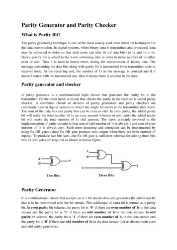
Parity Generator and Parity CheckerWhat is Parity Bit?The parity generating technique is one of the most widely used error detection techniques forthe data transmission. In digital systems, when binary data is transmitted and processed, datamay be subjected to noise so that such noise can alter 0s (of data bits) to 1s and 1s to 0s.Hence, parity bit is added to the word containing data in order to make number of 1s eithereven or odd. Thus it is used to detect errors during the transmission of binary data .Themessage containing the data bits along with parity bit is transmitted from transmitter node toreceiver node. At the receiving end, the number of 1s in the message is counted and if itdoesn’t match with the transmitted one, then it means there is an error in the data.Parity generator and checkerA parity generator is a combinational logic circuit that generates the parity bit in thetransmitter. On the other hand, a circuit that checks the parity in the receiver is called paritychecker. A combined circuit or devices of parity generators and parity checkers arecommonly used in digital systems to detect the single bit errors in the transmitted data word.The sum of the data bits and parity bits can be even or odd. In even parity, the added paritybit will make the total number of 1s an even amount whereas in odd parity the added paritybit will make the total number of 1s odd amount. The basic principle involved in theimplementation of parity circuits is that sum of odd number of 1s is always 1 and sum of evennumber of 1s is always zero. Such error detecting and correction can be implemented byusing Ex-OR gates (since Ex-OR gate produce zero output when there are even number ofinputs). To produce two bits sum, one Ex-OR gate is sufficient whereas for adding three bitstwo Ex-OR gates are required as shown in below figure.Parity GeneratorIt is combinational circuit that accepts an n-1 bit stream data and generates the additional bitthat is to be transmitted with the bit stream. This additional or extra bit is termed as a paritybit. In even parity bit scheme, the parity bit is ‘0’ if there are even number of 1s in the datastream and the parity bit is ‘1’ if there are odd number of 1s in the data stream. In oddparity bit scheme, the parity bit is ‘1’ if there are even number of 1s in the data stream andthe parity bit is ‘0’ if there are odd number of 1s in the data stream. Let us discuss both evenand odd parity generators.
Even Parity GeneratorLet us assume that a 3-bit message is to be transmitted with an even parity bit. Let the threeinputs A, B and C are applied to the circuits and output bit is the parity bit P. The totalnumber of 1s must be even, to generate the even parity bit P. The figure below shows thetruth table of even parity generator in which 1 is placed as parity bit in order to make all 1s aseven when the number of 1s in the truth table is odd.The K-map simplification for 3-bit message even parity generator isFrom the above truth table, the simplified expression of the parity bit can be written asThe above expression can be implemented by using two Ex-OR gates. The logic diagram ofeven parity generator with two Ex – OR gates is shown below. The three bit message alongwith the parity generated by this circuit which is transmitted to the receiving end where parity
checker circuit checks whether any error is present or not. To generate the even parity bit fora 4-bit data, three Ex-OR gates are required to add the 4-bits and their sum will be the paritybit.Odd Parity GeneratorLet us consider that the 3-bit data is to be transmitted with an odd parity bit. The three inputsare A, B and C and P is the output parity bit. The total number of bits must be odd in order togenerate the odd parity bit. In the given truth table below, 1 is placed in the parity bit in orderto make the total number of bits odd when the total number of 1s in the truth table is even.The truth table of the odd parity generator can be simplified by using K-map as
The output parity bit expression for this generator circuit is obtained asP (A B C)’Parity CheckIt is a logic circuit that checks for possible errors in the transmission. This circuit can be aneven parity checker or odd parity checker depending on the type of parity generated at thetransmission end. When this circuit is used as even parity checker, the number of input bitsmust always be even. When a parity error occurs, the ‘sum even’ output goes low and ‘sumodd’ output goes high. If this logic circuit is used as an odd parity checker, the number ofinput bits should be odd, but if an error occurs the ‘sum odd’ output goes low and ‘sum even’output goes high.Even Parity CheckerConsider that three input message along with even parity bit is generated at the transmittingend. These 4 bits are applied as input to the parity checker circuit which checks thepossibility of error on the data. Since the data is transmitted with even parity, four bitsreceived at circuit must have an even number of 1s. If any error occurs, the received messageconsists of odd number of 1s. The output of the parity checker is denoted by PEC (parityerror check). The below table shows the truth table for the even parity checker in which PEC 1 if the error occurs, i.e., the four bits received have odd number of 1s and PEC 0 if noerror occurs, i.e., if the 4-bit message has even number of 1s.
The above truth table can be simplified using K-map as shown below.The above logic expression for the even parity checker can be implemented by using threeEx-OR gates as shown in figure. If the received message consists of five bits, then one moreEx-OR gate is required for the even parity checking.Odd Parity CheckerConsider that a three bit message along with odd parity bit is transmitted at the transmittingend. Odd parity checker circuit receives these 4 bits and checks whether any error are presentin the data. If the total number of 1s in the data is odd, then it indicates no error, whereas ifthe total number of 1s is even then it indicates the error since the data is transmitted with oddparity at transmitting end. The below figure shows the truth table for odd parity generator
where PEC 1 if the 4-bit message received consists of even number of 1s (hence the erroroccurred) and PEC 0 if the message contains odd number of 1s (that means no error).The expression for the PEC in the above truth table can be simplified by K-map asAfter simplification, the final expression for the PEC is obtained asPEC (A Ex-NOR B) Ex-NOR (C Ex-NOR D)The expression for the odd parity checker can be designed by using three Ex-NOR gates asshown below.
checker. A combined circuit or devices of parity generators and parity checkers are commonly used in digital systems to detect the single bit errors in the transmitted data word. The sum of the data bits and parity bits can be even or odd. In even parity, the added parity bit will make the total number of 1s an even amount whereas in odd parity .