Transcription
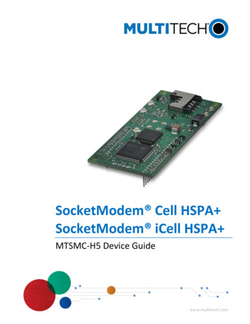
SocketModem Cell HSPA SocketModem iCell HSPA MTSMC-H5 Device Guide
LEGAL NOTICES AND CONTACT INFORMATIONSocketModem Cell HSPA and SocketModem iCell HSPA MTSMC-H5 Device GuideS000540, Version KMTSMC-H5-xx, MTSMC-H5-U-xx, MTSMC-H5-IP-xx, MTSMC-H5-GP-xx, MTSCMC-H5-MI-IP-xx, MTSMC-H5-MI-GPCopyrightThis publication may not be reproduced, in whole or in part, without the specific and express prior written permission signed by an executive officer ofMulti-Tech Systems, Inc. All rights reserved. Copyright 2019 by Multi-Tech Systems, Inc.Multi-Tech Systems, Inc. makes no representations or warranties, whether express, implied or by estoppels, with respect to the content, information, materialand recommendations herein and specifically disclaims any implied warranties of merchantability, fitness for any particular purpose and non-infringement.Multi-Tech Systems, Inc. reserves the right to revise this publication and to make changes from time to time in the content hereof without obligation ofMulti-Tech Systems, Inc. to notify any person or organization of such revisions or changes.TrademarksMultiTech is a trademark of and SocketModem, SocketWireless, Universal IP, SocketEthernet IP and the Multi-Tech logo are registered trademarks ofMulti-Tech Systems, Inc. All other brand and product names are trademarks or registered trademarks of their respective companies.Legal NoticesThe MultiTech products are not designed, manufactured or intended for use, and should not be used, or sold or re-sold for use, in connection withapplications requiring fail-safe performance or in applications where the failure of the products would reasonably be expected to result in personal injuryor death, significant property damage, or serious physical or environmental damage. Examples of such use include life support machines or other lifepreserving medical devices or systems, air traffic control or aircraft navigation or communications systems, control equipment for nuclear facilities, ormissile, nuclear, biological or chemical weapons or other military applications (“Restricted Applications”). Use of the products in such RestrictedApplications is at the user’s sole risk and liability.MULTITECH DOES NOT WARRANT THAT THE TRANSMISSION OF DATA BY A PRODUCT OVER A CELLULAR COMMUNICATIONS NETWORK WILL BEUNINTERRUPTED, TIMELY, SECURE OR ERROR FREE, NOR DOES MULTITECH WARRANT ANY CONNECTION OR ACCESSIBILITY TO ANY CELLULARCOMMUNICATIONS NETWORK. MULTITECH WILL HAVE NO LIABILITY FOR ANY LOSSES, DAMAGES, OBLIGATIONS, PENALTIES, DEFICIENCIES, LIABILITIES,COSTS OR EXPENSES (INCLUDING WITHOUT LIMITATION REASONABLE ATTORNEYS FEES) RELATED TO TEMPORARY INABILITY TO ACCESS A CELLULARCOMMUNICATIONS NETWORK USING THE PRODUCTS.The MultiTech products and the final application of the MultiTech products should be thoroughly tested to ensure the functionality of the MultiTechproducts as used in the final application. The designer, manufacturer and reseller has the sole responsibility of ensuring that any end user product intowhich the MultiTech product is integrated operates as intended and meets its requirements or the requirements of its direct or indirect customers.MultiTech has no responsibility whatsoever for the integration, configuration, testing, validation, verification, installation, upgrade, support ormaintenance of such end user product, or for any liabilities, damages, costs or expenses associated therewith, except to the extent agreed upon in asigned written document. To the extent MultiTech provides any comments or suggested changes related to the application of its products, suchcomments or suggested changes is performed only as a courtesy and without any representation or warranty whatsoever.Contacting MultiTechKnowledge BaseThe Knowledge Base provides immediate access to support information and resolutions for all MultiTech products. Visit http://www.multitech.com/kb.go.Support PortalTo create an account and submit a support case directly to our technical support team, visit: https://support.multitech.com.SupportBusiness Hours: M-F, 8am to 5pm CTCountryBy EmailBy PhoneEurope, Middle East, Africa:support@multitech.co.uk (44) 118 959 7774U.S., Canada, all others:support@multitech.com(800) 972-2439 or (763) 717-5863World HeadquartersMulti-Tech Systems, Inc.2205 Woodale DriveMounds View, Minnesota 55112Phone: 763-785-3500 or 800-328-9717Fax: 763-785-9874WarrantyTo read the warranty statement for your product, please visit: http://www.multitech.com/warranty.go.SocketModem Cell HSPA and SocketModem iCell HSPA MTSMC-H5 Device Guide2
CONTENTSContentsChapter 1 – Device Overview .6Description . 6Product Build Options . 6Documentation . 6Chapter 2 – Mechanical Drawing .7MTSMC-H5 All Builds . 7Chapter 3 – Specifications .8Technical Specifications . 8Frequency Bands . 10HE910 Telit Transmission Output Power . 10Mounting Hardware . 10Recommended Parts . 10Device Reset . 11Powering Down Your Device . 11Serial Signal DC Electrical Characteristics . 11Absolute Maximum Rating . 11Electrical Characteristics Other Pins . 11Pinout Specifications . 12Pin 58 . 13VUSB . 13Pin Availability by Build . 13Power Measurements . 14MTSMC-H5 . 14MTSMC-H5-U . 15MTSMC-H5-IP . 16MTSMC-H5-GP . 18MTSMC-H5-MI-IP . 19MTSMC-H5-MI-GP . 20Additional Information for the MTSMC-H5 Serial Device . 22Set Phone and Registration Functionality CFUN . 22GSM Power Saving Modes for Serial Devices. 23RTS Control of Power Mode AT CFUN 9. 24DTR Control of Power Mode AT CFUN 5 . 24Chapter 4 – Safety Notices . 25User Responsibility . 253SocketModem Cell HSPA and SocketModem iCell HSPA MTSMC-H5 Device Guide
CONTENTSDevice Maintenance . 25Vehicle Safety . 25Radio Frequency (RF) Safety . 26Interference with Pacemakers and Other Medical Devices. 26Potential interference . 26Precautions for pacemaker wearers . 26Notice Regarding Compliance with FCC, EU, and Industry Canada Requirements for RF Exposure . 27Chapter 5 – Regulatory Information. 28FCC Part 15 . 28FCC Grant Parts 22, 24, and 27 . 28Industry Canada . 29EMC, Safety, and Radio Equipment Directive (RED) Compliance (H5 and H5-U only) . 29Chapter 6 – Carrier Specific Information . 30Notice for Devices that Use Aeris Radios . 30Chapter 7 – Application Notes . 31LED Interface . 31LED 1 – Heartbeat – IP and –GP Builds Only . 31LED 2 – Link Status – All Builds . 31LED 3 – Signal Strength –IP and –GP Builds Only . 31LED 4 – GPS Status – GP Builds . 32RF Performances . 32Receiver Features . 32Transmitter Features. 32RF Connection and Antenna . 32Chapter 8 – Using Connection Manager . 33Installing Connection Manager . 33Setting Up a Serial Device in Windows Device Manager . 34Connecting a Device . 35Uninstalling Connection Manager . 37Connection Manager User Interface. 37Main tab . 38Settings tab . 38Connection tab . 39Details tab . 39Terminal tab . 39Charts tab . 39Troubleshooting . 39SocketModem Cell HSPA and SocketModem iCell HSPA MTSMC-H5 Device Guide4
CONTENTSSerial COM port is not available in the Serial Modem Settings . 39Device is not detected ("No Device") . 39MultiConnect Cell USB Modem is not detected . 40Connection Manager is not working, and a device connected to the computer is not detected . 40Connection Manager displays "Device Error" status for a serial device . 405SocketModem Cell HSPA and SocketModem iCell HSPA MTSMC-H5 Device Guide
CHAPTER 2 – MECHANICAL DRAWINGChapter 1 – Device OverviewDescriptionThe SocketModem Cell and iCell HSPA models are complete, ready-to-integrate communications devices thatoffer standards-based HSPA 21 performance. These quick-to-market communications devices allow developersto add wireless communication and GPS tracking to products with a minimum of development time and expense.Both models are based on industry-standard open interfaces and use MultiTech’s Universal Socket design. TheSocketModem iCell features the intelligence of the embedded Universal IP stack, which allows forautomatic/persistent connectivity for mission critical applications and enhanced M2M functionality.Product Build OptionsProductMTSMC-H5-MI-GPDescriptionGlobal HSPA 21M - Data Only, MTS GPS, Serial, USB, GPIO,Universal IPGlobal HSPA 21M - Data Only, Serial, USB, GPIO, Universal IPGlobal HSPA 21M - Data Only, MTS GPS, Serial, Universal IPGlobal HSPA 21M - Data Only, Serial, Universal IPGlobal HSPA 21M - Data Only, SerialGlobal HSPA 21M - Data Only, USBUniversal Developer KitMTSMC-H5-MI-IPMTSMC-H5-GPMTSMC-H5-IPMTSMC-H5 (RED compliant)MTSMC-H5-U (RED compliant)MTSMI-UDKNotes: These units ship without network activation. To connect them to the cellular network, you need a cellularaccount. For more information, refer to Account Activation for Cellular Devices in the Universal SocketDeveloper’s Guide. GP devices have a dedicated GPS receiver. MI devices have multiple interfaces. The complete product code may end in .Rx. For example, MTSMC-H5.Rx, where R is revision and x is the revisionnumber. All builds can be ordered individually or in 50-packs.DocumentationThe following documentation is available by email to oemsales@multitech.com or by using the Developer GuideRequest Form on the multitech.com Device Guide – This document. Provides model-specific specifications and developer information.Universal Socket Developer Guide – Provides an overview, safety and regulatory information, designconsiderations, schematics, and general device information. (S000342)USB Driver Installation Guide for H5 and G3 Devices – Provides steps for installing USB drivers. (S000533)AT Command Guide – Use the following AT Command Guides with HSPA devices: S000574 for H5-xx.R1 Modems 80378ST10091A Rev 9 Telit 3G Modules AT Commands Guide for H5-xx.R2 Modems S000528 for H5-xx Modems (not .R1 or .R2)S000457 Universal IP CommandsSocketModem Cell HSPA and SocketModem iCell HSPA MTSMC-H5 Device Guide6
CHAPTER 1 – DEVICE OVERVIEWChapter 2 – Mechanical DrawingMTSMC-H5 All Builds7SocketModem Cell HSPA and SocketModem iCell HSPA MTSMC-H5 Device Guide
CHAPTER 3 – SPECIFICATIONSChapter 3 – SpecificationsTechnical SpecificationsCategoryGeneralStandardsFrequency BandsSpeedData SpeedInterface, PortsUSB InterfaceSerial Modem InterfacePortsPhysical DescriptionWeightDimensionsConnectorsAntenna ConnectorSIM HolderEnvironmentOperating TemperatureStorage TemperatureHumidityPower RequirementsOperating VoltageIP, M2M, SMSSupported IP ProtocolsM2M ApplicationsSMSDescriptionPenta-band HSPA 21Quad-band GSM/GPRS/EDGESMS is based on CS/Packet-Switched (PS) domain of GSM and WCDMAUSB Interface is CDC-ACM compliantRefer to the following Frequency Bands table for details.HSPA : Up to 21.0 Mbps downlink/5.76 Mbps uplinkEDGE: Up to 296 Kbps downlink/236.8 Kbps uplinkGPRS: Up to 107 Kbps downlink/85.6 Kbps uplinkMI builds: USB 2.0 full speedHigh speed on other builds: 480 MbpsUp to 921.6 KbpsGPIO ports – MI builds only0.4 oz. (10g)Refer to mechanical drawing for details.3 surface mount UFL: main cellular, GPS, Auxiliary (for diversity)Standard 1.8V and 3V.-40 C to 85 C-40 C to 85 C20%-90% RH, non-condensing3.3V - 5V ( /- 10%)DNS resolve, FTP client, Ping, POP3 client, PPP (dialout), SMTP client, TCP RAW client &serverUniversal IP models: Automatic connect/reconnect, device monitor, modem emulation,Ping & TCP keep alive, wake-up on caller ID, wake-up on ring, GPS tracking (GP modelonly)Point-to-Point messagingMobile-Terminated SMSMobile-Originated SMSSocketModem Cell HSPA and SocketModem iCell HSPA MTSMC-H5 Device Guide8
CHAPTER 3 – SPECIFICATIONSCategoryDescriptionCertifications, Compliance, WarrantyEMC ComplianceFCC Part 15 Class BFCC Part 15.31 (Co-location)EN55022 Class BEN55024Radio ComplianceFCC Part 22FCC Part 24RSS 132RSS 133EN 301 511EN 301 489-1EN 301 489-52CE RED Radio/SARSafety ComplianceUL 60950-1cUL 60950-1EN 60950-1AS/NZS 60950-1Network CompliancePTCRBAT&TWarrantyTwo yearsNotes: 9Radio performance may be affected by temperature extremes. This is normal. The radio is designed toautomatically fallback in class and reduces transmitter power to avoid damage to the radio. When this occursdepends on the interaction of several factors, such as ambient temperature, operating mode, and transmitpower.SocketModem Cell HSPA and SocketModem iCell HSPA MTSMC-H5 Device Guide
CHAPTER 3 – SPECIFICATIONSFrequency BandsModeGSM850EGSM900DCS1800PCS1900WCDMA850(band V)WCDMA900(band VIII)WCDMA1700(band IV)WCDMA1900(band II)WCDMA2100(band I)Freq. TX (MHz)824.2- 848.8890.0 - 914.8Freq. RX (MHz)869.2 - 893.8935.0 - 959.8Channels128 - 2510 - 124TX - RX offset45 MHz45 MHz880.2 - 889.8925.2 - 934.8975 - 102345 MHz1710.2 - 1784.81850.2 - 1909.8826.4 - 846.61805.2 - 1879.81930.2 - 1989.8871.4 - 891.695MHz80MHz45MHz882.4 - 912.6927.4 - 957.61710.4 - 1755.62112.4 - 2167.61852.4 - 1907.61932.4 - 1987.61922.4 - 1977.62112.4 - 2167.6512 - 885512 - 810Tx: 4132 - 4233Rx: 4357 - 4458Tx: 2712 - 2863Rx: 2937 - 3088Tx: 1312 - 1513Rx: 9662 - 9938Tx: 9262 - 9538Rx: 9662 - 9938Tx: 9612 - 9888Rx: 10562 - 1083845MHz400MHz80MHz190MHzHE910 Telit Transmission Output PowerBandPower ClassGSM 850/900 MHzDCS 1800, PCS 1900 MHzEDGE, 850/900 MHzEDGE, 1800/1900 MHzWCDMA 850/900, AWS 1700, 1900/2100MHz4 (2W)1 (1W)E2 (0.5W)Class E2 (0.4W)Class 3 (0.25W)Mounting HardwareThe board has three mounting holes at corners. Use #4 or M3 hardware for mounting the SocketModem to theboard. Refer to the Mechanical Drawings for more information.Recommended PartsManufacturerPartPart NumberPEM PennEngineeringRAF Electronic HardwareRAF Electronic HardwareSurface Mount Standoff3/16” Hex Female Standoff4.5mm Hex Female -12-ZincSocketModem Cell HSPA and SocketModem iCell HSPA MTSMC-H5 Device Guide10
CHAPTER 3 – SPECIFICATIONSDevice ResetThe SocketModem is ready to accept commands after a fixed amount of time (“X” Time) after power-on or reset.ModelTime Constant"X" TimeMTSMC-H5250 ms10 seconds1The SocketModem may respond to a shorter reset pulse.Minimum Reset Pulse1200 µsMaximum Reset PulseLess than 1 secondPowering Down Your DeviceCAUTION: Failing to properly shutdown the device before removing power may corrupt your device's file system.To properly power down your device, use the following sequence:1. Issue the AT#SHDN command.2. Wait 30 seconds.3. Power off the device. Disconnect power from the device.Serial Signal DC Electrical CharacteristicsUnits: VoltsApplies to the following pins:PinJ33J34J35J36Signal Name-RTS-RXD-TXD-RIParameter3.3 Volt PoweredInput Low LevelInput High LevelOutput Low LevelOutput High Level5 Volt PoweredInput Low LevelInput High LevelOutput Low LevelOutput High LevelPinJ37J38J39J40Signal 0.553.302.303.70.850.555Absolute Maximum RatingAll models can run with an input voltage of either 3.3V or 5V. The maximum voltage on any signal pin equals theinput voltage.Electrical Characteristics Other Pins11SocketModem Cell HSPA and SocketModem iCell HSPA MTSMC-H5 Device Guide
CHAPTER 3 – SPECIFICATIONSPinSignal NameMinJ24J25J26J27J28J41J48Pin-RESETUSB VBUSGNDUSB DPUSB DNGNDGPIO0Signal NameJ49J50J51J58J61J63GPIO1GPIO2GPIO3-LED 85 3.3-----Pinout SpecificationsPinSignal NameLogic Level Voltage1 I/OJ24–RESET3.3 – 5.0IJ25VUSB4.4 – 5.25IJ26GNDGNDGNDJ27USB DP3.3I/OJ28USB OJ50GPIO23.3I/OJ51GPIO33.3I/OJ58–LED LINK3.3OJ61VCC5.0PWRJ63GNDGNDGND1 A hyphen (-) indicates a range of acceptable logic levels.SocketModem Cell HSPA and SocketModem iCell HSPA MTSMC-H5 Device GuideDescriptionDevice reset (active low)USB power supply inputGroundUSB dataUSB dataRequest to send (active low)Received data (active low)Transmitted data (active low)Ring indicator (active low)Data set ready (active low)Clear to send (active low)Data carrier detect (active low)Data terminal ready (active low)GroundUser configurable general purpose I/OUser configurable general purpose I/OUser configurable general purpose I/OUser configurable general purpose I/OLink status (active low, can sink up to 150mA)DC input powerGround12
CHAPTER 3 – SPECIFICATIONSPin 58Note: Pin 58 may or may not be available on some SocketModems.Pin 58 LED ModeOFFSlow blinkONOperating StatusDevice is offRegistered full serviceNet search or not registered, or in the process of turning offVUSBThe VUSB pin is the USB power input. This pin tells the modem that the USB bus exists. Its input range is 4.4-5.25V.To use the power saving mode, pull VUSB to LOW.Pin Availability by BuildPin and FunctionJ24 ResetJ25 USB VBUSJ26 GNDJ27 USB DPJ28 USB DNJ33 -RTSJ34 -RXDJ35 -TXDJ36 -RIJ37 -DSRJ38 -CTSJ39 -DCDJ40 -DTRJ41 GNDJ48 GPIOJ49 GPIOJ50 GPIOJ51 GPIOJ58 -LED LINKJ61 VCCJ63 xxxxxxxxxxxxxxxxxxH5-MI-GPxxxxxSocketModem Cell HSPA and SocketModem iCell HSPA MTSMC-H5 Device Guide
CHAPTER 3 – SPECIFICATIONSPower MeasurementsMultiTech recommends that you incorporate a 10% buffer into your power source when determining productload.MTSMC-H5Radio ProtocolAT command used to Time (sec) to reduced Time (sec) to “readyset radio functionpower from command for data connection”and power modeor DTE signal change from reduced powerRegistered PowerRadio Idle, SIMinstalled andconnected to tower3.3 VoltsGSM850/HSDPA AT CFUN 1N/AN/A30mAAT CFUN 5Approx. 1 secondApprox. 1 second17mAAT CFUN 7Approx. 1 secondApprox. 2 seconds17mA/30mAN/AN/A28mAAT CFUN 5Approx. 1 secondApprox. 1 second19mAAT CFUN 7Approx. 1 secondApprox. 2 seconds17mA/30mA5 VoltsGSM850/HSDPA AT CFUN 1RadioProtocolLow PowerMeasured MS XmitCurrentor Power(Amps)CntrlLevel3.3 VoltsGSM850 100mAHSDPA 286mA28Half PowerGSM XmitPower orHSDPA ChPowerMeas.(avg)Measured MS XmitCurrentor(Amps)PowerCntrlLevelMax PowerGSM XmitPower orHSDPA ChPowerMeas.(avg)Measured MS XmitCurrentor(Amps)PowerCntrlLevelGSM XmitPower orHSDPA g N/ABits288mAActiveBitsN/A610mAAll UpBitsN/AGSM850 72mA2874mA1513.02226mA032.88HSDPAAlternating N/ABits173mAActiveBitsN/A397mAAll UpBitsN/A5 Volts162mA4.75Note: This data is measured using an Agilent call box connected to the cellular radio.SocketModem Cell HSPA and SocketModem iCell HSPA MTSMC-H5 Device Guide14
CHAPTER 3 – SPECIFICATIONSRadioProtocolInstant Peak TXCurrent (Amps)Peak Reset Current Peak Reset Current(InRush) (Amps)(InRush) A1.95A3.12msHSDPA390mA1.95A3.12ms3.3 VoltsGSM850HSDPA5 VoltsNotes: AT CFUN 1 used to set radio function and power mode.Instant Peak Tx: The peak current during a GSM850 transmission burst period or HSDPA connection. Thiscurr
SMS is based on CS/Packet-Switched (PS) domain of GSM and WCDMA USB Interface is CDC-ACM compliant Frequency Bands Refer to the following Frequency Bands table for details. Speed Data Speed HSPA : Up to 21.0 Mbps downlink/5.76 Mbps uplink EDGE: Up to 296 Kbps downlink/236.8 Kbps uplink GPRS: Up to 107 Kbps downlink/85.6 Kbps uplink

