Transcription
LPC435x/3x/2x/1x32-bit ARM Cortex-M4/M0 MCU; up to 1 MB flash and 136 kBSRAM; Ethernet, two High-speed USB, LCD, EMCRev. 3 — 6 December 2012Preliminary data sheet1. General descriptionThe LPC435x/3x/2x/1x are ARM Cortex-M4 based microcontrollers for embeddedapplications which include an ARM Cortex-M0 coprocessor, up to 1 MB of flash and136 kB of on-chip SRAM, 16 kB of EEPROM memory, a quad SPI Flash Interface (SPIFI),advanced configurable peripherals such as the State Configurable Timer (SCT) and theSerial General Purpose I/O (SGPIO) interface, two High-speed USB controllers, Ethernet,LCD, an external memory controller, and multiple digital and analog peripherals. TheLPC435x/3x/2x/1x operate at CPU frequencies of up to 204 MHz.The ARM Cortex-M4 is a next generation 32-bit core that offers system enhancementssuch as low power consumption, enhanced debug features, and a high level of supportblock integration. The ARM Cortex-M4 CPU incorporates a 3-stage pipeline, uses aHarvard architecture with separate local instruction and data buses as well as a third busfor peripherals, and includes an internal prefetch unit that supports speculative branching.The ARM Cortex-M4 supports single-cycle digital signal processing and SIMDinstructions. A hardware floating-point unit is integrated in the core.The ARM Cortex-M0 coprocessor is an energy-efficient and easy-to-use 32-bit core whichis upward code- and tool-compatible with the Cortex-M4 core. The Cortex-M0coprocessor, designed as a replacement for existing 8/16-bit microcontrollers, offers up to204 MHz performance with a simple instruction set and reduced code size.2. Features and benefits Cortex-M4 Processor core ARM Cortex-M4 processor, running at frequencies of up to 204 MHz. ARM Cortex-M4 built-in Memory Protection Unit (MPU) supporting eight regions. ARM Cortex-M4 built-in Nested Vectored Interrupt Controller (NVIC). Hardware floating-point unit. Non-maskable Interrupt (NMI) input. JTAG and Serial Wire Debug (SWD), serial trace, eight breakpoints, and four watchpoints. Enhanced Trace Module (ETM) and Enhanced Trace Buffer (ETB) support. System tick timer. Cortex-M0 Processor core ARM Cortex-M0 co-processor capable of off-loading the main ARM Cortex-M4application processor. Running at frequencies of up to 204 MHz. JTAG
LPC435x/3x/2x/1xNXP Semiconductors32-bit ARM Cortex-M4/M0 microcontroller LPC435X 3X 2X 1XPreliminary data sheet Built-in NVIC.On-chip memory Up to 1 MB on-chip dual bank flash memory with flash accelerator. 16 kB on-chip EEPROM data memory. 136 kB SRAM for code and data use. Multiple SRAM blocks with separate bus access. Two SRAM blocks can bepowered down individually. 64 kB ROM containing boot code and on-chip software drivers. 64 bit of general-purpose One-Time Programmable (OTP) memory.Configurable digital peripherals Serial GPIO (SGPIO) interface. State Configurable Timer (SCT) subsystem on AHB. Global Input Multiplexer Array (GIMA) allows to cross-connect multiple inputs andoutputs to event driven peripherals like the timers, SCT, and ADC0/1.Serial interfaces Quad SPI Flash Interface (SPIFI) with four lanes and up to 52 MB per second. 10/100T Ethernet MAC with RMII and MII interfaces and DMA support for highthroughput at low CPU load. Support for IEEE 1588 time stamping/advanced timestamping (IEEE 1588-2008 v2). One High-speed USB 2.0 Host/Device/OTG interface with DMA support andon-chip high-speed PHY. One High-speed USB 2.0 Host/Device interface with DMA support, on-chipfull-speed PHY and ULPI interface to external high-speed PHY. USB interface electrical test software included in ROM USB stack. One 550 UART with DMA support and full modem interface. Three 550 USARTs with DMA and synchronous mode support and a smart cardinterface conforming to ISO7816 specification. One USART with IrDA interface. Up to two C CAN 2.0B controllers with one channel each. Use of C CAN controllerexcludes operation of all other peripherals connected to the same bus bridge SeeFigure 1 and Ref. 1. Two SSP controllers with FIFO and multi-protocol support. Both SSPs with DMAsupport. One SPI controller. One Fast-mode Plus I2C-bus interface with monitor mode and with open-drain I/Opins conforming to the full I2C-bus specification. Supports data rates of up to1 Mbit/s. One standard I2C-bus interface with monitor mode and with standard I/O pins. Two I2S interfaces, each with DMA support and with one input and one output.Digital peripherals External Memory Controller (EMC) supporting external SRAM, ROM, NOR flash,and SDRAM devices. LCD controller with DMA support and a programmable display resolution of up to1024 H 768 V. Supports monochrome and color STN panels and TFT colorpanels; supports 1/2/4/8 bpp Color Look-Up Table (CLUT) and 16/24-bit direct pixelmapping. Available on parts LPC4357/53 only. Secure Digital Input Output (SD/MMC) card interface.All information provided in this document is subject to legal disclaimers.Rev. 3 — 6 December 2012 NXP B.V. 2012. All rights reserved.2 of 151
LPC435x/3x/2x/1xNXP Semiconductors32-bit ARM Cortex-M4/M0 microcontroller LPC435X 3X 2X 1XPreliminary data sheet Eight-channel General-Purpose DMA controller can access all memories on theAHB and all DMA-capable AHB slaves. Up to 164 General-Purpose Input/Output (GPIO) pins with configurablepull-up/pull-down resistors. GPIO registers are located on the AHB for fast access. GPIO ports have DMAsupport. Up to eight GPIO pins can be selected from all GPIO pins as edge and levelsensitive interrupt sources. Two GPIO group interrupt modules enable an interrupt based on a programmablepattern of input states of a group of GPIO pins. Four general-purpose timer/counters with capture and match capabilities. One motor control Pulse Width Modulator (PWM) for three-phase motor control. One Quadrature Encoder Interface (QEI). Repetitive Interrupt timer (RI timer). Windowed watchdog timer (WWDT). Ultra-low power Real-Time Clock (RTC) on separate power domain with 256 bytesof battery powered backup registers. Alarm timer; can be battery powered.Analog peripherals One 10-bit DAC with DMA support and a data conversion rate of 400 kSamples/s. Two 10-bit ADCs with DMA support and a data conversion rate of 400 kSamples/s.Up to eight input channels per ADC.Unique ID for each device.Clock generation unit Crystal oscillator with an operating range of 1 MHz to 25 MHz. 12 MHz internal RC oscillator trimmed to 2 % accuracy over temperature andvoltage (1 % accuracy for Tamb 0 C to 85 C). Ultra-low power Real-Time Clock (RTC) crystal oscillator. Three PLLs allow CPU operation up to the maximum CPU rate without the need fora high-frequency crystal. The second PLL can be used with the High-speed USB,the third PLL can be used as audio PLL. Clock output.Power Single 3.3 V (2.2 V to 3.6 V) power supply with on-chip DC-to-DC converter for thecore supply and the RTC power domain. RTC power domain can be powered separately by a 3 V battery supply. Four reduced power modes: Sleep, Deep-sleep, Power-down, and Deeppower-down. Processor wake-up from Sleep mode via wake-up interrupts from variousperipherals. Wake-up from Deep-sleep, Power-down, and Deep power-down modes viaexternal interrupts and interrupts generated by battery powered blocks in the RTCpower domain. Brownout detect with four separate thresholds for interrupt and forced reset. Power-On Reset (POR).Available as LQFP208, LQFP144, LBGA256, or TFBGA100 packages.All information provided in this document is subject to legal disclaimers.Rev. 3 — 6 December 2012 NXP B.V. 2012. All rights reserved.3 of 151
LPC435x/3x/2x/1xNXP Semiconductors32-bit ARM Cortex-M4/M0 microcontroller3. Applications LPC435X 3X 2X 1XPreliminary data sheetMotor controlPower managementWhite goodsRFID readers Embedded audio applications Industrial automation e-meteringAll information provided in this document is subject to legal disclaimers.Rev. 3 — 6 December 2012 NXP B.V. 2012. All rights reserved.4 of 151
LPC435x/3x/2x/1xNXP Semiconductors32-bit ARM Cortex-M4/M0 microcontroller4. Ordering informationTable 1.Ordering informationType GA256Plastic low profile ball grid array package; 256 balls; body 17 17 1 mmSOT740-2LPC4357JET256LBGA256Plastic low profile ball grid array package; 256 balls; body 17 17 1 mmSOT740-2LPC4357JBD208LQFP208Plastic low profile quad flat package; 208 leads; body 28 28 1.4 mmSOT459-1LPC4353FET256LBGA256Plastic low profile ball grid array package; 256 balls; body 17 17 1 mmSOT740-2LPC4353JET256LBGA256Plastic low profile ball grid array package; 256 balls; body 17 17 1 mmSOT740-2LPC4353JBD208LQFP208Plastic low profile quad flat package; 208 leads; body 28 28 1.4 mmSOT459-1LPC4337FET256LBGA256Plastic low profile ball grid array package; 256 balls; body 17 17 1 mmSOT740-2LPC4337JET256LBGA256Plastic low profile ball grid array package; 256 balls; body 17 17 1 mmSOT740-2LPC4337JBD144LQFP144Plastic low profile quad flat package; 144 leads; body 20 20 1.4 mmSOT486-1LPC4337JET100TFBGA100 Plastic thin fine-pitch ball grid array package; 100 balls; body 9 9 0.7 mmLPC4333FET256LBGA256Plastic low profile ball grid array package; 256 balls; body 17 17 1 mmSOT740-2LPC4333JET256LBGA256Plastic low profile ball grid array package; 256 balls; body 17 17 1 mmSOT740-2LPC4333JBD144LQFP144Plastic low profile quad flat package; 144 leads; body 20 20 1.4 mmSOT486-1LPC4333JET100TFBGA100 Plastic thin fine-pitch ball grid array package; 100 balls; body 9 9 0.7 mmLPC4327JBD144LQFP144LPC4327JET100TFBGA100 Plastic thin fine-pitch ball grid array package; 100 balls; body 9 9 0.7 mmLPC4325JBD144LQFP144Plastic low profile quad flat package; 144 leads; body 20 20 1.4 mmPlastic low profile quad flat package; 144 leads; body 20 20 1.4 mmLPC4325JET100TFBGA100 Plastic thin fine-pitch ball grid array package; 100 balls; body 9 9 0.7 mmLPC4323JBD144LQFP144LPC4323JET100TFBGA100 Plastic thin fine-pitch ball grid array package; 100 balls; body 9 9 0.7 mmLPC4322JBD144LQFP144LPC4322JET100TFBGA100 Plastic thin fine-pitch ball grid array package; 100 balls; body 9 9 0.7 mmLPC4317JBD144LQFP144LPC4317JET100TFBGA100 Plastic thin fine-pitch ball grid array package; 100 balls; body 9 9 0.7 mmLPC4315JBD144LQFP144LPC4315JET100TFBGA100 Plastic thin fine-pitch ball grid array package; 100 balls; body 9 9 0.7 mmLPC4313JBD144LQFP144LPC4313JET100TFBGA100 Plastic thin fine-pitch ball grid array package; 100 balls; body 9 9 0.7 mmLPC4312JBD144LQFP144LPC4312JET100TFBGA100 Plastic thin fine-pitch ball grid array package; 100 balls; body 9 9 0.7 mmLPC435X 3X 2X 1XPreliminary data sheetPlastic low profile quad flat package; 144 leads; body 20 20 1.4 mmPlastic low profile quad flat package; 144 leads; body 20 20 1.4 mmPlastic low profile quad flat package; 144 leads; body 20 20 1.4 mmPlastic low profile quad flat package; 144 leads; body 20 20 1.4 mmPlastic low profile quad flat package; 144 leads; body 20 20 1.4 mmPlastic low profile quad flat package; 144 leads; body 20 20 1.4 mmAll information provided in this document is subject to legal disclaimers.Rev. 3 — 6 December SOT486-1SOT926-1SOT486-1SOT926-1SOT486-1SOT926-1 NXP B.V. 2012. All rights reserved.5 of 151
LPC435x/3x/2x/1xNXP Semiconductors32-bit ARM Cortex-M4/M0 microcontroller4.1 Ordering optionsGPIOTemperature range[1]ADC channelsQEIPWMUSB1 (Host, Device)/ULPI interfaceUSB0 (Host, Device, OTG)EthernetLCDTotal SRAMFlash bank BFlash totalFlash bank AOrdering optionsType numberTable 2.LPC4357FET2561 MB512 kB512 kB136 kByesyesyesyes/yes yesyes8F164LPC4357JET2561 MB512 kB512 kB136 kByesyesyesyes/yes yesyes8J164LPC4357JBD2081 MB512 kB512 kB136 kByesyesyesyes/yes yesyes8J142LPC4353FET256512 kB 256 kB256 kB136 kByesyesyesyes/yes yesyes8F164LPC4353JET256512 kB 256 kB256 kB136 kByesyesyesyes/yes yesyes8J164LPC4353JBD208512 kB 256 kB256 kB136 kByesyesyesyes/yes yesyes8J142LPC4337FET2561 MB512 kB512 kB136 kBnoyesyesyes/yes yesyes8F164LPC4337JET2561 MB512 kB512 kB136 kBnoyesyesyes/yes yesyes8J164LPC4337JBD1441 MB512 kB512 kB136 kBnoyesyesyes/yes yesno8J83LPC4337JET1001 MB512 kB512 kB136 kBnoyesyesyes/yes nono4J49LPC4333FET256512 kB 256 kB256 kB136 kBnoyesyesyes/yes yesyes8F164LPC4333JET256512 kB 256 kB256 kB136 kBnoyesyesyes/yes yesyes8J164LPC4333JBD144512 kB 256 kB256 kB136 kBnoyesyesyes/yes yesno8J83LPC4333JET100512 kB 256 kB256 kB136 kBnoyesyesyes/yes nono4J49LPC4327JBD1441 MB512 kB512 kB136 kBnonoyesno/noyesno8J83LPC4327JET1001 MB512 kB512 kB136 kBnonoyesno/nonono4J49LPC4325JBD144768 kB 384 kB384 kB136 kBnonoyesno/noyesno8J83LPC4325JET100768 kB 384 kB384 kB136 kBnonoyesno/nonono4J49LPC4323JBD144512 kB 256 kB256 kB104 kBnonoyesno/noyesno8J83LPC4323JET100512 kB 256 kB256 kB104 kBnonoyesno/nonono4J49LPC4322JBD144512 kB 512 kB0 kB104 kBnonoyesno/noyesno8J83LPC4322JET100512 kB 512 kB0 kB104 kBnonoyesno/nonono4J49LPC4317JBD1441 MB512 kB512 kB136 kBnononono/noyesno8J83LPC4317JET1001 MB512 kB512 kB136 kBnononono/nonono4J49LPC4315JBD144768 kB 384 kB384 kB136 kBnononono/noyesno8J83LPC4315JET100768 kB 384 kB384 kB136 kBnononono/nonono4J49LPC4313JBD144512 kB 256 kB256 kB104 kBnononono/noyesno8J83LPC4313JET100512 kB 256 kB256 kB104 kBnononono/nonono4J49LPC4312JBD144512 kB 512 kB0 kB104 kBnononono/noyesno8J83LPC4312JET100512 kB 512 kB0 kB104 kBnononono/nonono4J49[1]J -40 C to 105 C; F -40 C to 85 C.LPC435X 3X 2X 1XPreliminary data sheetAll information provided in this document is subject to legal disclaimers.Rev. 3 — 6 December 2012 NXP B.V. 2012. All rights reserved.6 of 151
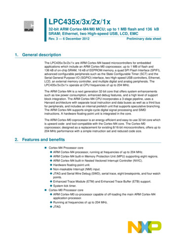
LPC435x/3x/2x/1xNXP Semiconductors32-bit ARM Cortex-M4/M0 microcontroller5. Block UGINTERFACEARMCORTEX-M0HIGH-SPEED PHYARMCORTEX-M4system busD-code busI-code busDMAETHERNET(1)10/100MACIEEE (1)HOST/DEVICELCD(1)SD/MMCmastersslavesAHB MULTILAYER MATRIXslavesBRIDGE 0BRIDGE 1BRIDGE 2BRIDGE 3BRIDGEBRIDGE64 kB ROM32 kB LOCAL SRAM40 kB LOCAL SRAMRI TIMERI2C1CGUALARM TIMERUSART0MOTORCONTROLPWM(1)USART210-bit DACCCU1BACKUP REGISTERSUART1I2C0USART3C CAN0CCU2POWER MODE CONTROLSSP0I2S0TIMER210-bit t ADC1TIMER1C CAN1WWDTSCUGPIOINTERRUPTSEVENT ROUTERSSP1OTP MEMORYQEI(1)RTCRTC OSCGIMA12 MHz IRCGPIO GROUP0INTERRUPTRTC POWER DOMAIN32 kB AHB SRAM16 kB 16 kB AHB SRAM16 kB EEPROM512/256 kB FLASH A512/256 kB FLASH BSCTEMCHS GPIOSPISGPIOSPIFIGPIO GROUP1INTERRUPT connected to DMA002aah234(1) Not available on all parts. See Table 2.Fig 1.LPC435x/3x/2x/1x Block diagramLPC435X 3X 2X 1XPreliminary data sheetAll information provided in this document is subject to legal disclaimers.Rev. 3 — 6 December 2012 NXP B.V. 2012. All rights reserved.7 of 151
LPC435x/3x/2x/1xNXP Semiconductors32-bit ARM Cortex-M4/M0 microcontroller6. Pinning information6.1 PinningLPC435x/3xFET256ball A1index area2143658710912111413ball A1index LGKMHNJPRKT002aah179002aah177Transparent top viewTransparent top viewPin configuration TFBGA100 package108104109LPC4357/53FBD208Fig 4.LPC433x/2x/1xFBD1441443715253120872002aah180Pin configuration LQFP208 packageFig 5.3615773Fig 3.105Pin configuration LBGA256 package156Fig 2.9 10002aah181Pin configuration LQFP144 package6.2 Pin descriptionOn the LPC435x/3x/2x/1x, digital pins are grouped into 16 ports, named P0 to P9 and PAto PF, with up to 20 pins used per port. Each digital pin can support up to eight differentdigital functions, including General Purpose I/O (GPIO), selectable through the SystemConfiguration Unit (SCU) registers. The pin name is not indicative of the GPIO portassigned to it.LPC435X 3X 2X 1XPreliminary data sheetAll information provided in this document is subject to legal disclaimers.Rev. 3 — 6 December 2012 NXP B.V. 2012. All rights reserved.8 of 151
LPC435x/3x/2x/1xNXP Semiconductors32-bit ARM Cortex-M4/M0 microcontrollerType32Description[1]LQFP14447Reset stateLQFP208TFBGA100Pin namePin descriptionLBGA256Table 3.Multiplexed digital pinsP0 0P0 1L3M2G2G15034[2][2]N;PUN;PUI/OGPIO0[0] — General purpose digital input/output pin.I/OSSP1 MISO — Master In Slave Out for SSP1.IENET RXD1 — Ethernet receive data 1 (RMII/MII interface).I/OSGPIO0 — General purpose digital input/output pin.-R — Function reserved.-R — Function reserved.I/OI2S0 TX WS — Transmit Word Select. It is driven by themaster and received by the slave. Corresponds to the signalWS in the I2S-bus specification.I/OI2S1 TX WS — Transmit Word Select. It is driven by themaster and received by the slave. Corresponds to the signalWS in the I2S-bus specification.I/OGPIO0[1] — General purpose digital input/output pin.I/OSSP1 MOSI — Master Out Slave in for SSP1.IENET COL — Ethernet Collision detect (MII interface).I/OSGPIO1 — General purpose digital input/output pin.-R — Function reserved.-R — Function reserved.ENET TX EN — Ethernet transmit enable (RMII/MIIinterface).P1 0P2LPC435X 3X 2X 1XPreliminary data sheetH15438[2]N;PUI/OI2S1 TX SDA — I2S1 transmit data. It is driven by thetransmitter and read by the receiver. Corresponds to the signalSD in the I2S-bus specification.I/OGPIO0[4] — General purpose digital input/output pin.ICTIN 3 — SCT input 3. Capture input 1 of timer 1.I/OEMC A5 — External memory address line 5.-R — Function reserved.-R — Function reserved.I/OSSP0 SSEL — Slave Select for SSP0.I/OSGPIO7 — General purpose digital input/output pin.I/OEMC D12 — External memory data line 12.All information provided in this document is subject to legal disclaimers.Rev. 3 — 6 December 2012 NXP B.V. 2012. All rights reserved.9 of 151
LPC435x/3x/2x/1xNXP Semiconductors32-bit ARM Cortex-M4/M0 microcontrollerP1 2P1 3P1 45842R3P5T3LPC435X 3X 2X 1XPreliminary data UTypeK2Description[1]LQFP144R2Reset stateLQFP208P1 1TFBGA100Pin namePin description continuedLBGA256Table 3.I/OGPIO0[8] — General purpose digital input/output pin. Boot pin(see Table 5).OCTOUT 7 — SCT output 7. Match output 3 of timer 1.I/OEMC A6 — External memory address line 6.I/OSGPIO8 — General purpose digital input/output pin.-R — Function reserved.I/OSSP0 MISO — Master In Slave Out for SSP0.-R — Function reserved.I/OEMC D13 — External memory data line 13.I/OGPIO0[9] — General purpose digital input/output pin. Boot pin(see Table 5).OCTOUT 6 — SCT output 6. Match output 2 of timer 1.I/OEMC A7 — External memory address line 7.I/OSGPIO9 — General purpose digital input/output pin.-R — Function reserved.I/OSSP0 MOSI — Master Out Slave in for SSP0.-R — Function reserved.I/OEMC D14 — External memory data line 14.I/OGPIO0[10] — General purpose digital input/output pin.OCTOUT 8 — SCT output 8. Match output 0 of timer 2.I/OSGPIO10 — General purpose digital input/output pin.OEMC OE — LOW active Output Enable signal.OUSB0 IND1 — USB0 port indicator LED controloutput 1.I/OSSP1 MISO — Master In Slave Out for SSP1.-R — Function reserved.OSD RST — SD/MMC reset signal for MMC4.4 card.I/OGPIO0[11] — General purpose digital input/output pin.OCTOUT 9 — SCT output 9. Match output 3 of timer 3.I/OSGPIO11 — General purpose digital input/output pin.OEMC BLS0 — LOW active Byte Lane select signal 0.OUSB0 IND0 — USB0 port indicator LED control output 0.I/OSSP1 MOSI — Master Out Slave in for SSP1.I/OEMC D15 — External memory data line 15.OSD VOLT1 — SD/MMC bus voltage select output 1.All information provided in this document is subject to legal disclaimers.Rev. 3 — 6 December 2012 NXP B.V. 2012. All rights reserved.10 of 151
LPC435x/3x/2x/1xNXP Semiconductors32-bit ARM Cortex-M4/M0 microcontrollerP1 6P1 scription[1]LQFP144R5Reset stateLQFP208P1 5TFBGA100Pin namePin description continuedLBGA256Table 3.I/OGPIO1[8] — General purpose digital input/output pin.OCTOUT 10 — SCT output 10. Match output 3 of timer 3.-R — Function reserved.OEMC CS0 — LOW active Chip Select 0 signal.IUSB0 PWR FAULT — Port power fault signal indicatingovercurrent condition; this signal monitors over-current on theUSB bus (external circuitry required to detect over-currentcondition).I/OSSP1 SSEL — Slave Select for SSP1.I/OSGPIO15 — General purpose digital input/output pin.OSD POW — SD/MMC power monitor output.I/OGPIO1[9] — General purpose digital input/output pin.ICTIN 5 — SCT input 5. Capture input 2 of timer 2.-R — Function reserved.OEMC WE — LOW active Write Enable signal.-R — Function reserved.OEMC BLS0 — LOW active Byte Lane select signal 0.I/OSGPIO14 — General purpose digital input/output pin.I/OSD CMD — SD/MMC command signal.I/OGPIO1[0] — General purpose digital input/output pin.IU1 DSR — Data Set Ready input for UART1.OCTOUT 13 — SCT output 13. Match output 3 of timer 3.I/OEMC D0 — External memory data line 0.OUSB0 PPWR — VBUS drive signal (towards external chargepump or power management unit); indicates that VBUS mustbe driven (active HIGH).Add a pull-down resistor to disable the power switch at reset.This signal has opposite polarity compared to the USB PPWRused on other NXP LPC parts.LPC435X 3X 2X 1XPreliminary data sheet-R — Function reserved.-R — Function reserved.-R — Function reserved.All information provided in this document is subject to legal disclaimers.Rev. 3 — 6 December 2012 NXP B.V. 2012. All rights reserved.11 of 151
LPC435x/3x/2x/1xNXP Semiconductors32-bit ARM Cortex-M4/M0 microcontrollerP1 9P1 10P1 117151T7R8T9LPC435X 3X 2X 1XPreliminary data UTypeH5Description[1]LQFP144R7Reset stateLQFP208P1 8TFBGA100Pin namePin description continuedLBGA256Table 3.I/OGPIO1[1] — General purpose digital input/output pin.OU1 DTR — Data Terminal Ready output for UART1.OCTOUT 12 — SCT output 12. Match output 3 oftimer 3.I/OEMC D1 — External memory data line 1.-R — Function reserved.-R — Function reserved.-R — Function reserved.OSD VOLT0 — SD/MMC bus voltage select output 0.I/OGPIO1[2] — General purpose digital input/output pin.OU1 RTS — Request to Send output for UART1.OCTOUT 11 — SCT output 11. Match output 3 of timer 2.I/OEMC D2 — External memory data line 2.-R — Function reserved.-R — Function reserved.-R — Function reserved.I/OSD DAT0 — SD/MMC data bus line 0.I/OGPIO1[3] — General purpose digital input/output pin.IU1 RI — Ring Indicator input for UART1.OCTOUT 14 — SCT output 14. Match output 2 of timer 3.I/OEMC D3 — External memory data line 3.-R — Function reserved.-R — Function reserved.-R — Function reserved.I/OSD DAT1 — SD/MMC data bus line 1.I/OGPIO1[4] — General purpose digital input/output pin.IU1 CTS — Clear to Send input for UART1.OCTOUT 15 — SCT output 15. Match output 3 of timer 3.I/OEMC D4 — External memory data line 4.-R — Function reserved.-R — Function reserved.-R — Function reserved.I/OSD DAT2 — SD/MMC data bus line 2.All information provided in this document is subject to legal disclaimers.Rev. 3 — 6 December 2012 NXP B.V. 2012. All rights reserved.12 of 151
LPC435x/3x/2x/1xNXP Semiconductors32-bit ARM Cortex-M4/M0 microcontrollerP1 13P1 14P1 157856R10R11T12LPC435X 3X 2X 1XPreliminary data UTypeK7Description[1]LQFP144R9Reset stateLQFP208P1 12TFBGA100Pin namePin description continuedLBGA256Table 3.I/OGPIO1[5] — General purpose digital input/output pin.IU1 DCD — Data Carrier Detect input for UART1.-R — Function reserved.I/OEMC D5 — External memory data line 5.IT0 CAP1 — Capture input 1 of timer 0.-R — Function reserved.I/OSGPIO8 — General purpose digital input/output pin.I/OSD DAT3 — SD/MMC data bus line 3.I/OGPIO1[6] — General purpose digital input/output pin.OU1 TXD — Transmitter output for UART1.-R — Function reserved.I/OEMC D6 — External memory data line 6.IT0 CAP0 — Capture input 0 of timer 0.-R — Function reserved.I/OSGPIO9 — General purpose digital input/output pin.ISD CD — SD/MMC card detect input.I/OGPIO1[7] — General purpose digital input/output pin.IU1 RXD — Receiver input for UART1.-R — Function reserved.I/OEMC D7 — External memory data line 7.OT0 MAT2 — Match output 2 of timer 0.-R — Function reserved.I/OSGPIO10 — General purpose digital input/output pin.-R — Function reserved.I/OGPIO0[2] — General purpose digital input/output pin.OU2 TXD — Transmitter output for USART2.I/OSGPIO2 — General purpose digital input/output pin.IENET RXD0 — Ethernet receive data 0 (RMII/MII interface).OT0 MAT1 — Match output 1 of timer 0.-R — Function reserved.I/OEMC D8 — External memory data line 8.-R — Function reserved.All information provided in this document is subject to legal disclaimers.Rev. 3 — 6 December 2012 NXP B.V. 2012. All rights reserved.13 of 151
LPC435x/3x/2x/1xNXP Semiconductors32-bit ARM Cortex-M4/M0 microcontrollerP1 17P1 18P1 199064M8N12M11LPC435X 3X 2X 1XPreliminary data ;PUTypeH9Description[1]LQFP144M7Reset stateLQFP208P1 16TFBGA100Pin namePin description continuedLBGA256Table 3.I/OGPIO0[3] — General purpose digital input/output pin.IU2 RXD — Receiver input for USART2.I/OSGPIO3 — General purpose digital input/output pin.IENET CRS — Ethernet Carrier Sense (MII interface).OT0 MAT0 — Match output 0 of timer 0.-R — Function reserved.I/OEMC D9 — External memory data line 9.IENET RX DV — Ethernet Receive Data Valid (RMII/MIIinterface).I/OGPIO0[12] — General purpose digital input/output pin.I/OU2 UCLK — Serial clock input/output for USART2 insynchronous mode.-R — Function reserved.I/OENET MDIO — Ethernet MIIM data input and output.IT0 CAP3 — Capture input 3 of timer 0.OCAN1 TD — CAN1 transmitter output.I/OSGPIO11 — General purpose digital input/output pin.-R — Function reserved.I/OGPIO0[13] — General purpose digital input/output pin.I/OU2 DIR — RS-485/EIA-485 output enable/direction control forUSART2.-R — Function reserved.OENET TXD0 — Ethernet transmit data 0 (RMII/MII interface).OT0 MAT3 — Match output 3 of timer 0.ICAN1 RD — CAN1 receiver input.I/OSGPIO12 — General purpose digital input/output pin.I/OEMC D10 — External memory data line 10.IENET TX CLK (ENET REF CLK) — Ethernet TransmitClock (MII interface) or Ethernet Reference Clock (RMIIinterface).I/OSSP1 SCK — Serial clock for SSP1.-R — Function reserved.-R — Function reserved.OCLKOUT — Clock output pin.-R — Function reserved.OI2S0 RX MCLK — I2S receive master clock.I/OI2S1 TX SCK — Transmit Clock. It is driven by the masterand received by the slave. Corresponds to the signal SCK inthe I2S-bus specification.All information provided in this document is subject to legal disclaimers.Rev. 3 — 6 December 2012 NXP B.V. 2012. All rights reserved.14 of 151
LPC435x/3x/2x/1xNXP Semiconductors32-bit ARM Cortex-M4/M0 microcontrollerP2 1]LQFP144M10Reset stateLQFP208P1 20TFBGA100Pin namePin description continuedLBGA256Table 3.I/OGPIO0[15] — General purpose digital input/output pin.I/OSSP1 SSEL — Slave Select for SSP1.-R — Function reserved.OENET TXD1 — Ethernet transmit data 1 (RMII/MII interface).IT0 CAP2 — Capture input 2 of timer 0.-R — Function reserved.I/OSGPIO13 — General purpose digital input/output pin.I/OEMC D11 — External memory data line 11.I/OSGPIO4 — General purpose digital input/output pin.OU0 TXD — Transmitter output for USART0. See Table 4 forISP mode.I/OEMC A13 — External memory address line 13.OUSB0 PPWR — VBUS drive signal (towards external chargepump or power management unit); indicates that VBUS mustbe driven (active HIGH).Add a pull-down resistor to disable the power switch at reset.This signal has opposite polarity compared to the USB PPWRused on other NXP LPC parts.P2 1N15LPC435X 3X 2X 1XPreliminary data sheetG711681[2]N;PUI/OGPIO5[0] — General purpose digital input/output pin.-R — Function reserved.IT3 CAP0 — Capture input 0 of timer 3.OENET MDC — Ethernet MIIM clock.I/OSGPIO5 — General purpose digital input/output pin.IU0 RXD — Receiver input for USART0. See Table 4 for ISPmode.I/OEMC A12 — External memory address line 12.IUSB0 PWR FAULT — Port power fault signal indicatingovercurrent condition; this signal monitors over-current on theUSB bus (external circuitry required to detect over-currentcondition).I/OGPIO5[1] — General purpose digital input/output pin.-R — Function reserved.IT3 CAP1 — Capture input 1 of timer 3.-R — Function reserved.All information provided in this document is subject to legal disclaimers.Rev. 3 — 6 December 2012 NXP B.V. 2012. All rights reserved.15 of 151
LPC435x/3x/2x/1xNXP Semiconductors32-bit ARM Cortex-M4/M0 microcontrollerP2 LQFP144M15Reset stateLQFP208P2 2TFBGA100Pin namePin description continuedLBGA256Table 3.I/OSGPIO6 — General purpose digital input/output pin.I/OU0 UCLK — Serial clock input/output for USART0 insynchronous mode.I/OEMC A11 — External memory address line 11.OUSB0 IND1 — USB0 port indicator LED control output 1.I/OGPIO5[2] — General purpose digital input/output pin.ICTIN 6 — SCT input 6. Capture input 1 of timer 3.IT3 CAP2 — Capture input 2 of timer 3.OEMC CS1 — LOW active Chip Select 1 signal.I/OSGPIO12 — General purpose digital input/output pin.I/OI2C1 SDA — I2C1 data input/output (this pin does not use aspecialized I2C pad).OU3 TXD — Transmitter output for USART3. See Table 4 forISP mode.ICTIN 1 — SCT input 1. Capture input 1 of timer 0. Captureinput 1 of timer 2.I/OGPIO5[3] — General purpose digital input/output pin.-R — Function reserved.OT3 MAT0 — Match output 0 of timer 3.OUSB0 PPWR — VBUS drive signal (towards external chargepump or power management unit); indicates that VBUS mustbe driven (active HIGH).Add a pull-down resistor to disable the power switch at reset.This signal has opposite polarity compared to the USB PPWRused on other NXP LPC par
Ultra-low power Real-Time Clock (RTC) on separate power domain with 256 bytes of battery powered backup registers. Alarm timer; can be battery powered. Analog peripherals One 10-bit DAC with DMA support and a data conversion rate of 400 kSamples/s. Two 10-bit ADCs with DMA support and a da ta conversion rate of 400 kSamples/s.
