Transcription
POWER AND SIGNAL INTEGRITY IMPROVEMENT IN ULTRAHIGH-SPEED CURRENT MODE LOGICHien Ha and Forrest BrewerUniversity of California Santa ng.ucsb.eduABSTRACTCurrent mode (ECL) logic has long been the option of choice inthose applications requiring logic functions at multigigahertzrates. This trend continues despite the obvious very high staticpower consumption and small signal swing characterizing thislogic. In this work we investigate a simple mechanism for LowVoltage-Swing Logic (LVSL) to greatly reduce the power requirement of a CML logic subsystem while improving the reliabilityand signal integrity. For the presented circuits operating at 5 GHz,50% power reduction is achieved while improving the signalintegrity.1. INTRODUCTIONHigh-speed applications such as telecommunications, microwavedigital processing, and satellite communications can benefitimmensely from an increase in logic function density and adecrease in power consumption. This is especially true for satellite communications. The more functionality that can be placedon a microchip, the lower the overall system cost. This economyof scale and low power is achieved in CMOS at clock frequenciesbelow a gigahertz.Presently, LSI applications which require operational speeds of5 GHz or higher are well beyond the domain of CMOS. IBMrecently fabricated a CMOS integer processor at 1 GHz [1] andothers have reported small circuits such as phase-locked loopsoperating at 3 GHz [2]. To date, no one has reported LSI CMOScircuits being clocked in excess of 5 GHz. CMOS power dissipation is heavily dependent on the clock frequency. This dynamicpower dissipation means that power savings of CMOS is small atmultigigahertz rates. The ECL logic family is primarily used atthese frequencies, even though ECL has other disadvantages.ECL often uses multiple power supplies which increases systemcomplexity and cost. Also, ECL dissipates much more staticpower than CMOS, making it impractical for LSI applications.Typically, implemention of a complex (LSI) function in ECLrequires splitting the function over several chips so that the powerbudget of each chip can be kept at a reasonable level. For complex systems, ECL is used only on the front and back ends. Thecomplex functions are implemented in CMOS at demultiplexedclock rates. This, again, increases system complexity and cost.Having a function split into several chips will reduce the overallperformance if there is a feedback loop in signalling over severalchips. It also increases overall power since more I/O pads areneeded to drive intermediate signals off-chip. The bottom line isthat there is no viable power-conserving technology for multigigahertz logic in portable applications although there have beenlow-power circuits in the lower gigahertz range of 3 GHz orless [3][4][5][6].An issue inherently connected to power dissipation is thermalmanagement. Higher heat decreases the reliability of the chip.Higher operating temperatures increase thermal noise and reducenoise margins. The large power dissipation in ECL means thatchip cooling is a serious concern. Water cooling might be neededfor LSI applications. The plumbing and refrigeration unit neededfor water cooling increase the system cost. Unlike CMOS, gatescannot always be placed a minimum distance apart. Some ECLgates dissipate such a large amount of power that if these gatesare placed too close together, hot spots can develop on the chip.This can be a problem even with water cooling because the thermal conductivity of the substrate may not be adequate to distribute the heat. Placing the gates further apart increases the wireparasitics and requires gates with larger drive capability to maintain the signal integrity. However, gates with larger drive alsohave a larger power dissipation which, in turn, forces the gateseven further apart. This cycle makes many large-scale designsimpractical.To address this problem, we need to analyze where most of thepower is being dissipated. Despite the large static power used inCML gates, most of the power is actually being dissipated in longwires and in support of long wires, particularly the clock-distribution network. The emitter followers used to drive long wires havegood drive capability but also dissipate a large amount of power.An example of the power budget distribution can be seen with a40-Gbit/s encoder chip designed and fabricated last year by ourgroup [7]. This chip performs channel encoding for a fiber datanetwork. The operating clock frequency is 5 GHz with new dataarriving on both clock edges. The chip has approximately 3800HBT transistors, dissipates 11.4W total, and is 4mm by 5mm. Thechip is large given the small number of transistors to keep thepower density reasonably low. Of the total power, 8.22W is due tobuffers of various types. Thus, 72% of the total power is dedicated to driving wires instead of performing logic functions. Thispercentage does not take into account the power dissipation fromthe pad drivers. If the pad drivers were factored in, the percentagewould be closer to 80%.
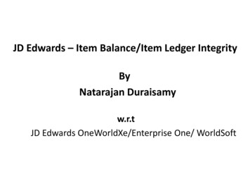
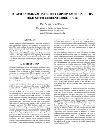
The power density of the encoder chip is 57 W/cm2. This powerdensity requires water cooling for proper operation. The circuittechnique we propose in this paper can reduce the power by 50%.If this technique is applied to the encoder then the power densitywill drop to 28.5 W/cm2, thus allowing the chip to be air cooled.In fact, this new power density is in the same range as today’smost advanced CMOS chips. The Alpha 21264 microprocessorhas a power density of 22.9 W/cm2 [8] and is air-cooled.1400bp bn 1400360360930930ap2. TECHNICAL DISCUSSIONAs the majority of the power dissipation is due to driving longwires, it is obvious that reducing the power of the logic gateswould result in minimal improvements in total power reduction.To reduce the power substantially, the buffers driving long wiresneed to be changed. If the voltage swings can be reduced whilemaintaining large current swings, then the effect of parasiticcapacitance in long wires can be minimized. Further, we canmatch the drive to the wire impedance, thus improving the signalintegrity. Typical high-speed CML already has relatively smallvoltage swings of 300 mV; If this swing could be dropped to50 mV while maintaining large current swings, the large parasiticcapacitances of long wires will not greatly increase rise and falltimes. Thus long wires can be driven with considerably smallerbuffers and yield large power savings. If the gates driving longwires dissipate less power, gates can then be placed closertogether, thus reducing wire lengths and parasitics. This tighterplacement, in turn, allows further reduction in the power of thegates and a large decrease in power dissipation results.There are different solutions for LVSL and for addressing thehigh-speed low-power problem in general. Some of these aretransistor techniques [9][10][11] while others are circuit techniques [12][13][14][15][16][17][18][19]. The solution proposedin this proposal is a circuit technique called TransimpedanceTransconductance Logic (ZGL). A ZGL buffer with differentialinput and output is shown in Figure 1. Basically, transimpedanceamplifiers are added to the differential inputs of a CML gate.Nodes ap and an are the differential inputs to the transimpedanceamplifiers which consist of Q1, Q2 and the biasing resistors.Since a transimpedance amplifier translates small current swingsto large voltage swings, the internal nodes of a ZGL gate whichare not dominated by large interconnect parasitics have the normal voltage swings of ECL gates. The output side of the gate(nodes bp, bn) is a transconductance amplifier which has a currentswing proportional to the input voltage swing. This allows longinterconnect wires to be driven by gates with a voltage swing assmall as 50 mV. The resistors can be adjusted for impedancematching and current drive.anQ2Q11.0mA1.5mAFigure 1. ZGL buffer with differential input(a)and output(b)inductance and 1.24 nh/mm of mutual inductance. Note that theuse of differential interconnect is common with most currentmode logic. There are several benefits of differential wires oversingle-ended wires. The first benefit is that there are fewer gatesin the overall design. This is because the complement of everysignal is available. The second benefit of differential wires is animprovement of signal integrity. The third benefit is a built-inreturn-current path for every signal wire. Signals are compared totheir complements so shifts in the ground voltage do not affectdifferential reception. At first, it may seem that routing is morecongested and problematic than for the single-ended interconnectcommon in CMOS. However, as mentioned earlier, the layout ofcurrent mode logic is limited by the power density more than bythe gate-to-gate interconnect.A circuit for measuring the parasitic effects on ZGL gates can beseen in Figure 2. This is a series of the ZGL buffers from Figure 1driving a pair of differential wires 3mm in length. The input forthe first buffer is a periodic pulse train. The second buffer is driving the long differential wires. The wire length is modeled with anRLC ladder. The results can be seen in Figure 3. The nodes plotted are the input and output of the second and third buffers. Thenodes ap, an and yp, yn are the differential input and output of thesecond buffer. The nodes y12p, y12n and z0p, z0n are the inputand output of the third buffer. The power is the total power of allfour gates. These results can be compared to Figure 4 which is asimulation of the same circuit but with ECL emitter followers.There is substantially more ringing in the ECL circuit. This illustrates one of the benefits of ZGL. The low impedance on the inputside of the receiver’s transimpedance stage matches with the lowimpedance on the output side of the driver’s transconductanceExperiments on the drive properties of ZGL buffers were performed in Hspice. All tests were on circuits running at 5 GHz.The tests on ZGL gates driving long wires were performed withRC and RLC parasitics. The resistance of the wires was estimatedto be 20 ohms/mm. The capacitance of the differential wires wasestimated to be 80 ff/mm to ground and 68 ff/mm to each other.Finally, the inductance was estimated to be 1.46 nh/mm of selfFigure 2. ZGL buffers driving long differential wires
Figure 3. ZGL buffer driving long differential wireFigure 5. ZGL buffers in seriesstage. Also, the power dissipation of the ECL circuit is threetimes larger than the ZGL equivalent.The power-delay product of ZGL gates is worse than ECL gates ifthere is no RLC loading on the buffers as can be seen in Figure 5and Figure 6. These two figures are results of the same circuit inFigure 2, except there is no long wire segment between buffers 2and 3. That is, the buffers are connected directly to each other.With RLC loading for a long wire as seen in Figure 2 andFigure 3, the power-delay product is markedly better than ECL.As chips get larger, the interconnect delay will dominate the gatedelay so the ndividual gate delay matters less. This dominance ininterconnect delay can be seen in the previous examples.The ability of ZGL buffers to drive clock trees and long wires wasput to the test in the aforementioned encoder chip. A major subsystem of the encoder was simulated with all ECL gates and theresult was compared with the same subsystem having all the ECLbuffers replaced by ZGL buffers. This subsystem is a populationcounter which counted the number of 1s in a 4-bit input. The original subsystem with all ECL gates dissipated 830mW while themixed version dissipated 445mW. The mixed version simply hadall the ECL clock buffers replaced with ZGL buffers. Both cir-Figure 6. ECL buffers in seriescuits were designed to operate at 5GHz and were simulated at 5and 6GHz with RLC parasitics, with the parasitic capacitancesbeing extracted from the actual layout. The Hspice outputs (at6GHz) of the ECL and mixed versions are shown in Figure 7 andFigure 8, respectively. It should be noted that this power saving isobtained with the original placement and parasitics. In reality, thepower savings is even greater because the gates can now beplaced closer together with the correspondingly lower parasitics.As seen in Figure 7 and Figure 8, the signals for the mixed version of the population counter are noticably cleaner than the pureFigure 4. ECL buffer driving long differential wire
ECL version. The mixed version is also slightly faster than theECL version. This improvement in speed and noise is due to thebetter impedance matching on long wires. Driver sizes in the ECLversion were dictated by signal integrity and were very largewhich, of course, dissipated a great deal of power. The improvement in impedance matching and power-delay product for longwires using ZGL means that the circuit does not have to be overdesigned by such a large margin.3. CONCLUSIONFigure 7. ECL implementation of population counterFigure 8. ZGL and ECL implementation of populationcounter4. REFERENCES[1] H. Hofstee, et al., “Designing for a gigahertz,” IEEE Micro,vol. 18, no. 3, p. 66-74, 1998.[2] B. Razavi, et al., “A 3-GHz 25-mW CMOS phase-lockedloop,” Symposium on VLSI Circuits, p. 131-2, 1994.[3] K. Koike, K. Kawai, et al., “High-speed, low-power, bipolarstandar cell design methodology for Gbit/s signal processing,” IEEE Journal of Solid-State Circuits, vol. 33, no. 10, p.1536-44, Oct. 1998.[4] K. Kishine, Y. Kobayashi, and H. Ichino, “A high-speed,low-power bipolar digital circuit for Gb/s LSI’s: current mirror control logi,” IEEE Journal of Solid-State Circuits, vol.32, no. 2, p. 215-21, Feb. 1997.[5] H. Yamashina and H. Yamada, “An MOS current mode logic(MCML) circuit for low-power GHz processors,” NEC Research and Development, vol. 36, no. 1, p. 54-63, Jan. 1995.[6] R. M. Hickling, et al., “Low power components for 1 Gb/soptical communications: A single-chip 10-channel opticalreceiver and a clock recovery circuit,” IEEE Gallium Arsenide Integrated Circuit Symposium, p. 201-4, 1997.[7] A. Vittal, H. Ha, F. Brewer, and M. Marek-Sadowska,“Clock skew optimization for ground bounce control,” International Conference on Computer-Aided Design, p. 395-9,1996.[8] M. Gowan, L. Biro, D. Jackson, “Power Considerations inthe design of the Alpha 21264 microprocessor,” Design Automation Conference, p. 726-31, 1998.[9] M. Kondo, et al., “Sub-10-fJ ECL/68-uA 4.7-GHz dividerultra-low-power SiGe base bipolar transistors with a wedgeshaped CVD-SiO2 isolation structure and a BPSG-refilledtrench,” International Electron Devices Meeting, p. 245-8,1996.[10] M. Kondo, et al., “Ultra-low-power and high-speed SiGebase bipolar transistors for wireless telecommunication systems,” IEEE Transactions on Electron Devices, vol. 45, no.6, p. 1287-94, June 1998.[11] T. Onai, E. Ohue, et al., “Self-aligned complementary bipolar technology for low-power dissipation and ultra-highspeed LSIs,” IEEE Transactions on Electron Devices, vol.42, no. 3, p. 413-8, March 1995.[12] R. Golshan and B Haroun, “A novel reduced swing CMOSBUS interface circuit for high speed low power VLSI systems,” International Symposium on Circuits and Systems, p.351-4, 1994.[13] C. Chuang and K. Chin, “High-speed low-power direct-coupled complementary push-pull ECL circuit,” IEEE Journalof Solid-State Circuits, vol.29, no. 7, p. 836-9, July 1994.[14] K. Sharaf and M. Elmasry, “Low-power differential CMLand ECL BiCMOS circuit techniques,” Fourth Great LakesSymposium, p. 208-13, 1994.[15] A. Onozawa, H. Kitazawa, K. Kawai, “Post-layout optimization of power and timing for ECL LSIs,” European Designand Test Conference, p. 167-172, 1995.
[16] V. G. Oklobdzija, “An ECL gate with improved speed andlow power in a BiCMOS process,” IEEE Journal of SolidState Circuits, vol. 31, no. 1, p. 77-83, Jan. 1996.[17] N. Sasaki, H. Sato, et al., “A new emitter-follower circuit forhigh-speed and low-power ECL,” IEICE Transactions onElectronics, vol. E78-C, no. 4, p. 374-80, April 1995.[18] W. Wilhelm and P. Weger, “2V low-power bipolar logic,”IEEE International Solid-State Circuits Conference, p. 94-5,1994.[19] M. Mizuno, M. Yamashina, et al., “A GHZ MOS adaptivepipeline technique using variable delay circuits,” Symposiumon VLSI Circuits, p. 27-8, 1994.
University of California Santa Barbara hienha@aurora.ece.ucsb.edu forrest@engineering.ucsb.edu ABSTRACT Current mode (ECL) logic has long been the option of choice in those applications requiring logic functions at multigigahertz rates. This trend continues despite the obvious very high static power consumption and small signal swing .