Transcription
POLITECNICO DI TORINODepartment of Electronics and TelecommunicationsM.Sc in Communications and Computer NetworksEngineeringMaster ThesisNetwork slicing and QoS in5G systems and theirimpact on the MAC layerAdvisors:Dr. Carla Fabiana ChiasseriniDr. Achim NahlerAuthor:Enida MatajJuly 10, 2020
iiiAbstract5G is the new generation of cellular communication systems that will provide servicenot only for mobile users, but also for business unites. Different use-cases have been introduced along with 5G such as Enhanced Mobile Broadband Communication (eMBB),Ultra Reliable Low Latency Communication (URLLC) and Massive Machine Type ofCommunication (mMTC). Compared to well-established 4G communication systemsbased on LTE technologies, the requirements for these services are higher in terms oflow latency 1ms (e.g. for cellular communication support of autonomous driving, remote surgery and industrial automation), high bit rate in values of Gbps. Despite theenhancements introduced for 5G NR (New Radio) with Release 15 by 3GPP, it is quitechallenging and inefficient to meet all the service requirements within the same network.In order to fulfill the requirements set by International Telecommunication Union (ITU),it has been proposed Network Slicing as a possibility to set up and configure logical networks per each use case. Network Slicing (NS) is thought as a network virtualizationtechnique that will make the network more flexible by optimising the utilisation of theinfrastructure and the allocation of resources.This thesis will focus on analysing Network Slicing and Quality of Service (QoS)Framework from 3GPP Standards and not only. Then, Media Access Control (MAC)will be analyzed by pointing out the changes for Network Slicing and QoS deployments.Last, emulations will be carried out to show the impact of dedicated network slicing andQoS in the network performance.Keywords: 5G, Network Slicing, eMBB, mMTC, URLLC, Quality of Service, MAClayer.
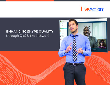
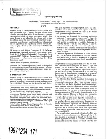
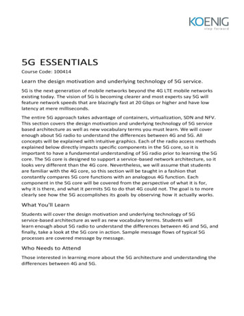
Context & MotivationPriMO-5G ProjectPriMO-5G is a joint project from Korean and European partners within the HORIZON2020 framework. This project is willing to develop 5G system based on mmWavefor fire-fighting scenarios. The consortium believes that recent enhancements on mobilecommunication technology shall improve the rescue process in Public Protection andDisaster Relief (PPDR) scenarios.The project is focused on fire-fighting use-case and the intention is to develop technologies of mmWave access, 5G core networks and AI-assisted communications fulfillingnetwork requirements. The project use-cases and the scenarios are described in the deliverable [38] which is a public document and can be found on the website: www.primo5g.euFigure 1: Fire-fighting scenario PriMO-5G. Figure 4.4 from [38]This thesis is based on the scenario as shown in the figure 1 which represents a firefighting scenario in a forest where the mobile network coverage is not feasible. Therefore, vehicular gNB shall provide network connectivity for the rescue team, drones androbots. Furthermore, it shall contain computing resources or the so called Multi-accessEdge Computing (MEC) in order process the traffic. The drones will receive the controlcommands from gNB and will send live streaming traffic towards gNB. In this way itwill become easier to manage the situation and instruct the rescue team and the robots.A brief description of each components shown in the Figure 1 is given:iv
vFirefighters are equipped with UEs for voice connection with the gNBRobots will be simple UEs and can be used for management or data transmission.The robots that are equipped with moving gNBs will be managed remotely to allocatenetwork and radio slices required for other devices with low latency requirements suchas UAVs.UAVs, similar to robots, can be simple UEs or Unmanned Aerial Vehicles (UAVs)that carry aerial gNB which then should be managed from URLLC controller.Incident commander is assumed to locate at a fire engine which is capable ofgNB, MEC and URLLC network slice management functions. If the fire break-out is ina large scale, the incident commander will need connectivity to the control centre. Thus,the fire truck should also have wireless backhaul to the closest available infrastructure.From the above scenario are driven 2 main use-cases enhanced Mobile BroadbandCommunication (eMBB) and Ultra Reliable Low Latency Communication (URLLC).The mentioned use-cases have different network requirements in terms of delay, packetloss and throughput which makes it difficult to meet the service requirements if theyrun in one network. Therefore, it was needed to analyze the performance of NetworkSlicing and / or Quality of Service on fulfilling the use-case KPIs.Based from the described scenario, the research work of this thesis has been motivated.
Dedikuar prindërve të mi.
ContentsAbstractiiiContext & MotivationvAbbreviationxiiList of FiguresxiiiList of Tables11 Introduction22 5G System Overview2.1 Introduction . . . . . . . . . . . . . .2.2 Service-Based Architecture . . . . .2.2.1 Core Network Functions . . .2.2.2 Service Model Connection . .2.3 Cloud RAN . . . . . . . . . . . . . .2.3.1 RAN Split Options . . . . . .2.3.2 RAN deployment scenarios .2.3.3 RAN architecture by O-RAN2.4 Summary . . . . . . . . . . . . . . .5556777911123 RAN Protocols3.1 Introduction . . . . . . . . . . . . . . . . . .3.2 Radio Resource Control - RRC . . . . . . .3.3 Service Data Adaption Protocol - SDAP . .3.4 Packet Data Convergence Protocol - PDCP3.5 Radio Link Control - RLC . . . . . . . . . .3.6 Media Access Control - MAC . . . . . . . .3.7 Physical Layer . . . . . . . . . . . . . . . .3.8 Summary . . . . . . . . . . . . . . . . . . .131314161820222426.2727282829303031324 Network Slicing4.1 Introduction . . . . . . . . . . . . . .4.2 Composition of Network Slicing . . .4.2.1 3GPP Communication model4.2.2 Core Network Slicing . . . . .4.2.3 RAN Slicing . . . . . . . . .4.2.4 RAN Principles - 3GPP . . .4.2.5 Core Network selection . . .4.2.6 Radio Resource Managementvii.
viii4.34.44.54.6Orchestration of Network Slicing . . . . . . . . .4.3.1 Network Slicing Management by 3GPP .4.3.2 Network Slicing Orchestration by ETSI .4.3.3 Network Slicing Orchestration - O-RANImpact on Radio Protocol Layers . . . . . . . . .4.4.1 Slice Descriptors . . . . . . . . . . . . . .4.4.2 RAN Slicing Examples by NOKIA . . . .Network Slice Deployment Scenarios . . . . . . .Summary . . . . . . . . . . . . . . . . . . . . . .5 QoS model5.1 Introduction . . . . . . . . . . . . . . . .5.2 QoS Flows . . . . . . . . . . . . . . . . .5.2.1 QoS Profile . . . . . . . . . . . .5.2.2 QoS Rules . . . . . . . . . . . . .5.2.3 Packet Detection Rules (PDRs) .5.3 QoS Flow Mapping . . . . . . . . . . . .5.3.1 Mapping procedure in Uplink . .5.3.2 Mapping procedure in Downlink5.4 Impact on Radio Protocol Layers . . . .5.5 Summary . . . . . . . . . . . . . . . . .6 Enhancements in 5G MAC Layer6.1 Introduction . . . . . . . . . . . . . . .6.2 MAC Architecture . . . . . . . . . . .6.3 Scheduling Procedure . . . . . . . . .6.3.1 Uplink Scheduling . . . . . . .6.3.2 Downlink Scheduling . . . . .6.4 Logical Channel Prioritization . . . . .6.5 Buffer Status Reporting . . . . . . . .6.6 Research on 5G Scheduling Algorithms6.7 Summary . . . . . . . . . . . . . . . . . . . . . . . . . . . . . . . . . . . . . . . . . . . . . . . . . . .outside of. . . . . .7 Simulation Environment7.1 PAL Setup Introduction(Confidential). . . . . . . . . . . . . . . . . . . . . . . . .7.2 System Parameters(Confidential). . . . . . . . . . . . . . . . . . . . . . . . .7.3 Ideal Simulation Scenarios . . . . . . . . . .7.4 Selected Scenarios . . . . . . . . . . . . . .7.4.1 Network Slicing - Scenario . . . . . .7.4.2 Quality of Service Scenario . . . . .7.4.3 Various Packet Length Scenario . . .7.4.4 Scenarios with different MCS index .7.5 Network Slicing Configuration(Confidential). . . . . . . . . . . . . . . . . . . . . . . . .7.6 QoS Configuration(Confidential). . . . . . . . . . . . . . . . . . . . . . . . .333334353637373940.4141424345464647495052. . . . . . . . . . . . . . . . . . . . . .3GPP. . . .5353535455575859606162. . . . . . . . . . . . . . . .62.62626364656566. . . . . . . . . . . . . . . .66. . . . . . . . . . . . . . . .66.
ix7.77.8Traffic Generation . . . . . . . . . . . . .7.7.1 Packet Analysis on RAN Stack . .Simulation ResultsPartially Confidential . . . . . . . . . . .7.8.1 Network Slicing - Default Use-Case7.8.2 Quality of Service Scenario . . . .7.8.3 Various Packet Length Scenario . .7.8.4 Different MCS Index Scenario . . . . . . . . . . . . . . . . . . . . . . . . . . . . . . . . . . .6668.6969707172.8 Conclusions74References78Acknowledgement82
AbbreviationITU3GPPNGMNO-RAN5G NRCN5G FAUSFNSSAIInternational Telecommunication UnionThe 3rd Generation Partnership ProjectNext Generation Mobile NetworksOpen-Radio Access Network5th Generation New RadioCore Network5G Core NetworkLong-Term Evolutionenhanced Mobile Broadband Communicationmassive Machine Type CommunicationUltra Reliable Low Latency CommunicationKey Performance IndicatorControl PlaneUser PlaneRadio Access NetworkCloud - Radio Access NetworkNext Generation - Radio Access NetworkCentralized UnitDistributed UnitRadio UnitO-RAN Centralized UnitO-RAN Distributed UnitO-RAN Radio UnitPhysical Network FunctionVirtual Network FunctionCore Network FunctionMachine LearningArtificial IntelligenceMulti-access Edge ComputingAccess & Mobility Management FunctionSession Management FunctionUser Plane FunctionUnified Data RepositoryUnified Data ManagementPolicy Control FunctionNetwork Repository FunctionNetwork Exposure FunctionNetwork Slice Selection FunctionAuthentication Server FunctionNetwork Slice Selection Assistance Informationx
etwork Slice Selection Assistance InformationService-Based ArchitectureNetwork Function VirtualizationSoftware Defined NetworksAccess Networknon Access NetworkRadio Resource ControlService Data Adaption ProtocolPacket Data Convergence ProtocolService Data Convergence ProtocolRadio Link ControlRadio Link Control Acknowledged ModeRadio Link Control Unacknowledged ModeRadio Link Control Transparent ModeMedia Access ControlRadio BearerPhysical Radio BearerData Radio BearerSignaling Radio BearerRadio Resource ManagementProtocol Data UnitService Data UnitTracking AreaDedicated Control ChannelDedicated Traffic ChannelCommon Control ChannelPaging Control ChannelBroadcast Control ChannelPhysical Uplink Control ChannelPhysical Uplink Shared ChannelPhysical Downlink Control ChannelPhysical Downlink Shared ChannelPhysical Random Access ChannelPhysical Broadcast ChannelData Plane Development KitLogical ChannelLogical Channel IdentifierLogical Channel PrioritizationAutomatic repeat requestHybrid Automatic Repeat RequestBuffer Status ReportPower Headroom ReportSemi-Persistent SchedulingTime Division MultiplexingFrequency Division MultiplexingTime Division DuplexingModulation and Coding schemeDownlink Control InformationTransport BlockTransport Block SizeChannel Quality IndicatorReference Signal Receive Power
SMFNFV-MANORICUAVsPPDRBlock Error RateSignal to Noise RatioCarrier AggregationCell-Radio Network Temporary IdentifierInterruption Network Temporary IdentifierDiscontinuous ReceptionRound RobinWeighted Round RobinProportional Fair SchedulingEarliest Deadline FirstQuality of Service Flow Identifier5G Quality of Service IndicatorReflective Quality of Service IndicatorReflective Quality of Service to Data Radio Bearer IndicatorGuaranteed Flow Bit Ratenon-Guaranteed Flow Bit RateAllocation and Retention PriorityMaximum Data Burst VolumeMaximum Flow Bit RateMaximum Packet Loss RateAggregate Maximum Bit RatePacket Delay BudgetPacket Error RatePacket Detection RulePacket Flow DescriptionReflective QoS AttributeDifferentiated Services Code PointNetwork SlicingNetwork Slice Selection Assistance InformationSingle Network Slice Selection Assistance InformationSlice/Service TypeSlice DifferentiatorTemporal IdentifierNetwork Slice InstanceNetwork Slice Subnet InstanceTransport NetworkOrchestration and ManagementCommunication Service Management FunctionNetwork Slice Communication FunctionNetwork Slice Subnet Management FunctionNetwork Function Virtualization Management and OrchestrationRadio Access Network Intelligence ControllerUnmanned Aerial VehiclesPublic Protection and Disaster Relief
List of Figures1Fire-fighting scenario PriMO-5G. Figure 4.4 from [38] . . . . . . . . . .iv1.15G Use-Cases defined by ITU. . . . . . . . . . . . . . . . . . . . . . . . .22.12.22.32.45782.85G - Service-Based Architecture. Figure 4.2.3-1 from [1] . . . . . . . . .NRF-NF communication. Figure from [28] . . . . . . . . . . . . . . . . .RAN Functional Split Options - 3GPP. Figure 11.1.1-1 from [6] . . . . .RAN Architecture Split Option 2 - 3GPP. Figure 6.1.2-1 from 3GPP TS38.401 [9] . . . . . . . . . . . . . . . . . . . . . . . . . . . . . . . . . . .RAN Deployment Scenario 1 - 3GPP. Figure 6.2.2-1 from 3GPP TS 38.806[7] . . . . . . . . . . . . . . . . . . . . . . . . . . . . . . . . . . . . . . .RAN Deployment Scenario 2 - 3GPP. Figure 6.2.2-2 from 3GPP TS 38.806[7] . . . . . . . . . . . . . . . . . . . . . . . . . . . . . . . . . . . . . . .RAN Deployment Scenario 3 - 3GPP. Figure 6.2.2-3 from 3GPP TS 38.806[7] . . . . . . . . . . . . . . . . . . . . . . . . . . . . . . . . . . . . . . .O-RAN Radio Access Network Architecture. Figure 4 from [27] . . . . .11113.13.23.33.43.53.63.73.83.93.10User Plane Protocol Stack. Figure 4.4.1-1 from 3GPP TS 38.300 [11] . .Control Plane Protocol Stack. Figure 4.4.2-1 from 3GPP TS 38.300 [11]UE state machine and state transitions in NR. Figure 4.2.1-1 from [5] .SDAP Sublayer - structure view. Figure 4.2.1-1 from [12] . . . . . . . .SDAP Layer - functional view. Figure 4.2.2-1 from [12] . . . . . . . . . .PDCP Layer - structure view. Figure 4.2.1-1 from [13] . . . . . . . . . .PDCP Layer - functional view. Figure 4.2.2-1 from [13] . . . . . . . . .PDCP Layer - Packet Duplication. Figure 16.1.3-1 from [11] . . . . . . .Overview model of the RLC Sublayer. Figure 4.2.1-1 from [14] . . . . .MAC Architecture. Figure 4.2.2-1 from [15] . . . . . . . . . . . . . . . .13141516171819202122fig: 5G Network Slicing Architecture. Figure from [33] . . . . . . . . . .End to End services provided by NSI(s) - 3GPP. Figure 4.9.3.1 from [4]E2E Network Slicing Architecture. Figure from [31] . . . . . . . . . . .S-NSSAI structure. Figure from [11] . . . . . . . . . . . . . . . . . . . .AMF Selection. Figure 16.3.4.2-1 from 3GPP TS 38.300 [11] . . . . . .Network Slice related management functions - 3GPP. Figure 4.10.1 from3GPP TR 28.801 .[4] . . . . . . . . . . . . . . . . . . . . . . . . . . . . .4.7 Management aspects of network slice instance (NSI) - 3GPP. Figure4.3.1.1 from 3GPP TS 28.530 [3] . . . . . . . . . . . . . . . . . . . . . .4.8 Slicing Orchestration in 3GPP and ETSI NFV MANO. Figure from [23]4.9 O-RAN Orchestration & Management Architecture . Figure from [26] .4.10 RAN Slice Descriptors. Figure from [35] . . . . . . . . . . . . . . . . . .4.11 Ultra-Low-Latency (1ms) Deployment. Figure from NGMN [24] . . . . .4.12 Deployment Topology for 10ms Latency. Figure from NGMN [24] . . 43536373940
5.15.25.35.45.55.65.7QoS Flows in 4G & 5G. . . . . . . . . . . . . . . . . .QoS Flows Mapping in 5G. Figure taken from [1] . . .QoS Flows Signalling in 5G. . . . . . . . . . . . . . .N1 SM Signaling Network- UE. Figure 8.3.2.1.1 from[10] . . . . . . . . . . . . . . . . . . . . . . . . . . . . .Uplink QoS Mapping - Signaling Flow . . . . . . . . .Downlink QoS Mapping - Signaling Flow . . . . . . . .User Plane Stack for one PDU Session. . . . . . . . . . . . . . . . . . . . . . . . .3GPP TS. . . . . . . . . . . . . . . . . . . . . . . . . . . . . .24.501. . . . . . . . . . . . .6.16.26.36.46.56.6MAC Architecture. Figure 4.2.2-1 from [15] . . . . . . . . . . . . .Dynamic Uplink Scheduling . . . . . . . . . . . . . . . . . . . . . .Configured Uplink Grant Type 1 & 2 . . . . . . . . . . . . . . . . .Pre-emptive Scheduling in Downlink . . . . . . . . . . . . . . . . .Logical Channel Prioritization procedure at UE. Figure from cite[]2-Level Scheduling Model by EUROCOM. Figure 2 from [36] . . .48495051.545657585961Scenario - 2 slices & QoS Flows Enabled . . . . . . . . . . . . . . . . . .Sub-Scenarios with 1 eMBB Slice . . . . . . . . . . . . . . . . . . . . . .Sub-Scenarios with 2 eMBB Slices . . . . . . . . . . . . . . . . . . . . .Sub-Scenarios with 3 eMBB Slices . . . . . . . . . . . . . . . . . . . . .Packet Analysis on RAN Protocol Stack . . . . . . . . . . . . . . . . . .L2 Data Flow Example. Figure 6.6-1 from 3GPP TS38.300 [11] . . . . .Network Slice Throughput - Default Scenarios 7.3 . . . . . . . . . . . . .QoS Impact on Throughput . . . . . . . . . . . . . . . . . . . . . . . . .Iperf vs L1 Throughput Comparison - Packet Length Sub scenario (10Mbps) . . . . . . . . . . . . . . . . . . . . . . . . . . . . . . . . . . . . .7.10 MCS Impact on Maximum Achieved Throughput . . . . . . . . . . . . 77273
List of Tables3.13.23.33.4Functions Summary - RLC Entities . . . . . . . . . . . . . . . . . . . . .Definition of frequency ranges. Table 5.1-1 from [19] . . . . . . . . . . .Supported transmission numerologies. Table from 3GPP 38.300 [11] . .Number of OFDM symbols per slot, slots per frame, and slots per subframe for normal cyclic prefix. Table 4.3.2-1 from 3GPP 38.211 [17] . .254.14.24.3Standardized SST values. Table 5.15.2.2-1 from 3GPP TS 23.501 [1] . .AMF Selection. . . . . . . . . . . . . . . . . . . . . . . . . . . . . . . . .RAN Slice Examples by Nokia [32] . . . . . . . . . . . . . . . . . . . . .3132385.1Qos Parameters - QoS Flow . . . . . . . . . . . . . . . . . . . . . . . . .457.17.27.37.47.57.67.77.87.97.10QoS Flows - Table 5.7.4-1 from [1] . . . .Summary of Ideal Simulation Scenarios [1]Default Scenarios with Network Slicing . .Scenarios with Quality of Service . . . . .Scenarios with various packet length . . .MCS index tested. Table 5.1.3.1-1 [16] . .Default UseCase Throughput Results . . .QoS Use-Case - Throughput Results . . .Packet Length impact on Throughput . .TBS and Maximum estimated TPT . . .636365656666697172721.222424
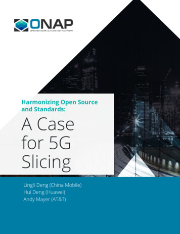
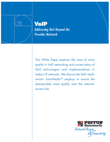
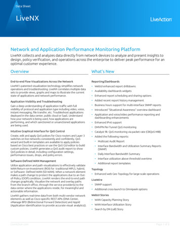
Chapter 1IntroductionDue to the huge success of of 4th generation of cellular communication systems basedon LTE technologies, 5G is designed to not only provide higher data rate, but alsoto support a diverse set of new services coming from vertical industry. InternationalTelecommunication Union (ITU) has set diverse application-specific requirements to besupported by 5th Generation Mobile Network.Three main service categories have been defined as 5G Use-Cases as shown in Figure1.1: Enhanced mobile broadband (eMBB), ultra-reliable and low-latency communication (URLLC) and massive machine-type communication (mMTC).Figure 1.1: 5G Use-Cases defined by ITU.Enhanced Mobile Broadband Communication (eMBB) is a data-driven usecase for serving mobile users requiring high data rates.Ultra Reliable Low Latency Communication (URLLC) is designed to servefor mission critical communications with strict latency and reliability requirements suchas remote surgery or autonomous vehicles.Massive Machine Type Communications (mMTC) is thought to serve a very2
CHAPTER 1. INTRODUCTION3large number of devices such as Internet of Things (IoT) and sensors, which may onlysend data sporadically. These type of devices do not require high bit rate, but thereare restrictions in terms of network coverage underground(e.g. basement), extendedbattery-life to several years.Recent European research projects, stakeholders, as well as the 3GPP, have issuedseveral 5G architectures that support network slicing.Th 3rd Generation Partnership Project (3GPP) is a collaborative project betweenseven telecommunication organizations, focused on developing standards that are globally acceptable. The project is composed of 3 main work groups that aim researching ondifferent areas: Technical Specification Group for Radio Access Networks (TSG RAN),for Core Network & Terminal (TSG CT) and for Service & System Aspects (TSG SA).The standards are published in form of Technical Specifications and Technical Reports.The latter contains proposed solutions for specific topic that need to be further discussedand analyzed. Whereas, the former provides the standardized solutions obtained afterseveral group meetings and discussions. The documents are available online and free ofcharge. The first phase of 3GPP 5G specifications has been completed with Release 15,December 2017. The second phase in Release 16 is scheduled for completion in 2020.Other stakeholders such as O-RAN Alliance and Next Generation Mobile Networks(NGMN) are as well working on this topic and have published their proposals and specifications on respective websites.O-RAN Alliance is an organization driven mostly by network operators such as : suchas China Mobile and AT&T aiming to standardize the protocol interfaces needed forreal network implementation. Their solutions are adopted from 3GPP specifications andwilling to facilitate open in a sense of exchangeable infrastructure components.The services to enable eMBB, URLLC and mMTC use cases have different needs interms of network performance, such as low latency access, high communication reliability and the support of massive number of devices. Therefore, the static point-to-pointarchitecture currently in use by 4G is no more sufficient to fulfill the diverse set of requirements. This led to think of designing the network architecture in a more flexibleway. In order to make the network more flexible and configurable, has been proposed theseparation of Control Plane Functionalities from the User Plane Functionalities. Thisseparation is possible by enabling network virtualization techniques: Network FunctionVirtualization (NFV), Software Defined Network (SDN) and cloud computing. SDN allows to have a centralized control plane that manages the user plane functions deployedon different scenarios. Through network virtualization it is possible to run the networkfunctions such as routers, firewalls on a general-purpose server and configure the networkbased on the operator needs. Switching from a point-to-point network architecture towards a Service Based Architecture (SBA), makes easier the separation of Control PlaneNetwork Functions from User Plane Network Functions. This configurable and flexiblearchitecture allows enabling of logical networks through common network functions andimprove the service. Network slicing is thought as a solution of creating virtual networksthat share the network infrastructure. Hence guarantee the heterogeneous requirementsof the vertical industry.On the other hand, Radio Access Network Architecture has been defined by 3GPP inRelease 15 and can be implemented as C-RAN (Cloud-RAN). It is an architecture whereC-RAN is a centralized, cloud computing-based architecture for radio access networks.C-RAN, which is a composition of Centralized Unit and Distributed Unit, has managedto separate the control plane from the user plane also. The radio protocol stack between
4CHAPTER 1. INTRODUCTIONthe UE and gNB, has been defined for control plane and user plane. Based on thedefined architecture, RRC, SDAP and PDCP sublayer will run at Centralized Unit(CU) component. Whereas the lower radio protocol stack layer will run at DistributedUnit (DU). Since 3GPP has not defined the so called Fronthaul Interface between theDistributed Unit and the Radio Unit, making it a vendor depended protocol interface,O-RAN Alliance is researching to set the standards.The following characteristics highlight the enhancements of 5G System from LongTerm Evolution (LTE): Service Based Architecture, Network Slicing, New Radio.Service-based Architecture (SBA) is based on the premise that 5G will supporta multitude of services and very different performance requirements. The differencecompared to P2P architecture used in LTE, stands at the control plane. In LTE architecture, components were connected with predefined connections. Whereas in SBA hasbeen applied another elements has been introduced: NF Repository Function (NRF)which connects network elements following the service model approach. Each networkelement query an NF Repository Function (NRF) to discover and communicate witheach other. Hence, the network is more flexible to add new network element instancesand services.Software Defined Network (SDN) enables the separation of control plane fromuser plane. 5G aims to create a centralized control plane that manages and configuresuser plane network functions. In order to provide the means of isolated control functions, 5G architecture has been designed with a separate User Plane Function (UPF) ,Access and Mobility Function (AMF) and Session Management Function (SMF).Network Slicing is expected to be a key component of future 5G networks due tovariety of services supported by 5G. Enabling configurable logical networks with functionality specific to the service or customer. Some scenarios that might need specificslices are: autonomous car communication require low latency whereas video - streamingrequires high throughput.New Radio (NR) has been introduced as a radio access technology able to meetthe requirements of each aforementioned use-cases. It promises to provide better userexperience through serving in ultra low latency and higher throughput. Several features have been enhanced comparing with LTE such as: utilization of higher frequencybands, massive MIMO, flexible numerology. Transmitting on higher frequency bandsdoes not have good channel conditions. On the other hand, flexible numerology permitsenabling variable duration slots. Doing so, is possible to assign short duration slots toUser Equipment (UEs) serving URLLC traffic.The thesis is organized as follows: Chapter 2 provides an overview of fundamentalfeatures of 5G System, covering the core network architecture, enhancements on NewRadio compared to LTE. Chapter 3 described the functionalities and structure of radioprotocol stack starting from Radio Resource Control Layer down to Physical Layer.Chapter 4 and 5 investigate on Network Slicing and Quality of Service (QoS) framework,respectively. Chapter 6 provides an analysis of required features by MAC Protocol Layerfor supporting Network Slicing and Quality of Service. Chapter 7 describes the systemenvironment used for testing, the emulation scenarios and the obtained results. Finally,chapter 8 describes conclusions on obtained results and future scope.
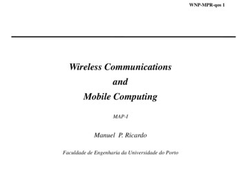
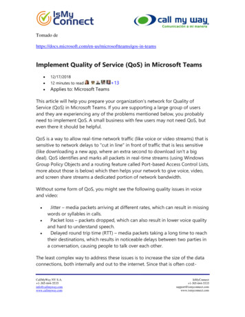
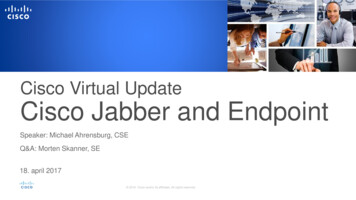
Chapter 25G System Overview2.1Introduction5G is thought as a dynamic and flexible framework willing to serve diverse services withspecific network requirement. 5G is designed to provide flexibility on Core network andRAN deployment such as Cloud-RAN and Service-Based Architecture. In the followingsubsections will be described aspects of 5G System that are relevant to understandNetwork Slicing and Quality of Service approach. The references for this chapter aremainly three technical specifications (TS) from 3GPP, as following: TS 23.501 [1], TS38.300 [11] and TR 28.801 [4].2.2Service-Based ArchitectureCore Network (CN) architecture used in LTE has some drawbacks in terms of complexity and scalability such as: a lot of interfaces to be established and diverse protocolsused per connection. Hence, it is not possible to support diverse services required in 5G.Figure 2.1: 5G - Service-Based Architecture. Figure 4.2.3-1 from [1]Therefore, another flexible solution has been proposed by 3GPP (Figure 2.1), Service Based Architecture (SBA). It represents a cloud-networking approach where CoreNetwork Functions (CNFs) that reside in Control Plane (CP), are connecting through a5
6CHAPTER 2. 5G SYSTEM OVERVIEWservice model interface. Each NF can behave as a service producer by offering servicesto other NFs, or service customer by requesting services from other NFs. The component that makes the communication possible is Network Repository Function (NRF).NFs from Control Plane register their services on NRF and
Context & Motivation PriMO-5G Project PriMO-5G is a joint project from Korean and European partners within the HORI-ZON2020 framework. This project is willing to develop 5G system based on mmWave