Transcription
DellEMC Enterprise Systems Rail Sizing and Rack Compatibility MatrixDellEMCTM Enterprise Systems RailSizing and Rack Compatibility MatrixThis document provides mounting features and key dimensions of therack rails used for mounting many DellEMC enterprise systems andperipheral devices in a rack enclosure.
DellEMC Enterprise Systems Rail Sizing and Rack Compatibility MatrixThis document is for informational purposes only and may contain typographical errors and technicalinaccuracies. The content is provided as is, without express or implied warranties of any kind. 2020 DellEMC. All rights reserved. Reproduction of this material in any manner whatsoever withoutthe express written permission of DellEMC is strictly forbidden.DellEMC, the DELLEMC logo, PowerEdge, PowerVault, ReadyRails, RapidRails, VersaRails, EqualLogicand Compellent are trademarks of DellEMC. Other trademarks and trade names may be used in thisdocument to refer to either the entities claiming the marks and names or their products. DellEMCdisclaims any proprietary interest in trademarks and trade names other than its own.May 2020 Version 3.8ii
DellEMC Enterprise Systems Rail Sizing and Rack Compatibility MatrixContentsIntroduction . 1Considerations . 1Mounting interface . 2Rail types - System Installation Method . 3Cable Management Solutions . 4Backwards compatibility . 4Self-Adjusting Slide Feature . 6Definitions - Reference for Table 2 . 6FiguresTablesTable 1.DellEMC server rails compatibility chart . 4Table 2.DELLEMC Rail Sizing Matrix . 8Table 3.DellEMC rack compatibility matrix . 17iii
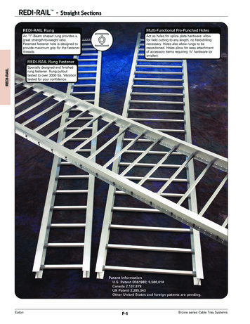
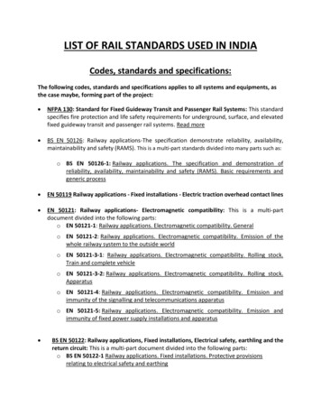
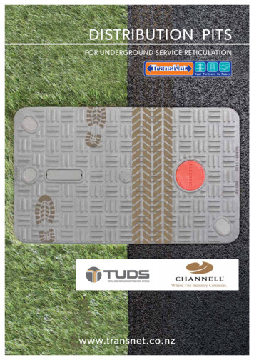
Dell Enterprise Systems Rail Sizing and Rack Compatibility MatrixIntroductionThis document provides information about the mounting features and key dimensions of the rack rails used for mounting manyDellEMC enterprise systems and peripheral devices in a rack enclosure. This document also provides a compatibility summaryfor select DellEMC racks as well as some common third-party racks. Note that the product list is not all-inclusive and updates willbe made as needed.The dimensions provided in this document are for reference only. Some minor deviations due to manufacturing tolerances andvariances should be expected.DellEMC rail kits may not be compatible with racks from other vendors, however, all DellEMC rail kits are designed forcompliance with all EIA-310-D and later revision specifications for 19-inch racks.ConsiderationsPlease pay attention to the footnotes indicated in the tables because they provide important information on using the rails indifferent racks and circumstances.It is assumed that rack mount peripherals and cable bundles do not protrude into the space directly behind the systems.Note that DellEMC rail kits with a Rail Identifier code have been designed to be compliant with the Server System Infrastructure(SSI) Specification for Computer Server Cabinet Enclosures & Racks, which specifies a minimum offset distance for return flangeson the rack mounting flanges to allow sufficient room for mounting the rail kits, as indicated in Figure 1. For more informationabout the Server System Infrastructure (SSI) Specification for Computer Server Cabinet Enclosures & Racks, see the SSI Forum atssiforum.org.Figure 1.Top view of right front EIA mounting flangeSome third-party racks may not meet this requirement, and although DellEMC has made extensive efforts to accommodate asmany third-party racks as possible, it is not feasible to provide a solution for every circumstance.1
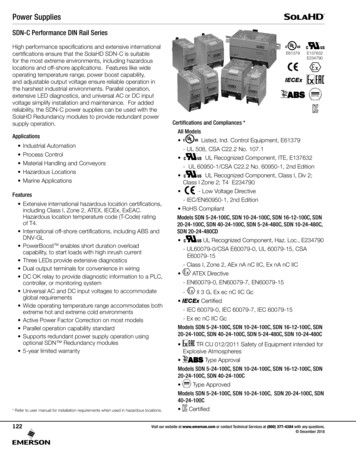
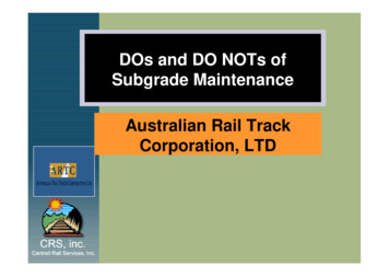
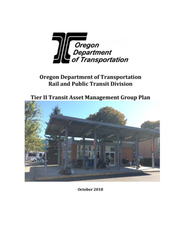
DellEMC Enterprise Systems Rail Sizing and Rack Compatibility MatrixMounting interfaceThe ReadyRails II mounting interface supports tool-less installation in 4-post square-hole and unthreaded round-hole racks aswell as native support for tooled installation in threaded-hole racks. Note that installing this mounting interface in a square-holerack allows the bracket to be placed flush against the mounting post, while installation in a round-hole rack results in a slightoffset of approx. 6 mm from the mounting post, which also results in an approx. 6 mm bezel offset; refer to Figure 2.Figure 2.System offset for round-hole racks6.1mmThe original ReadyRails mounting interface is used for both static and sliding rails, and it supports tool-less installation in 4-postsquare-hole and unthreaded round-hole racks. Static ReadyRails kits also support tooled installation in threaded-hole racks and2-post racks. When installed in unthreaded round-hole racks, the original ReadyRails will also have the 6 mm offset from themounting post that was discussed in the previous ReadyRails II paragraph. In order to install sliding ReadyRails kits into athreaded-hole rack, adapter brackets are required. 1U and 2U adapter bracket kits are available that support systems rangingfrom 1U to 5U in height.The adapter bracket kits include six brackets to accommodate different rail lengths, plus four sets of custom screws in 10-32,12-24, M5 and M6 thread sizes. The design of the brackets has been optimized to limit the forward shift of the system in the rackto only 17.3 mm. Depending on the depth of the rack used and the position of the mounting rails within the rack, it may benecessary to remove the system’s bezel in order to close the front door of the rack. For the front door to close with the systembezel installed, a minimum clearance of 58 mm is needed between the back surface of the door panel and the front face of theEIA flange.The RapidRails mounting interface supports tool-less installation in 4-post square-hole racks only, while the VersaRails mounting interface supports tooled installation in 4-post square-hole and unthreaded round-hole racks. Mounting the VersaRailsin threaded-hole racks is not recommended and is not supported by DellEMC.2
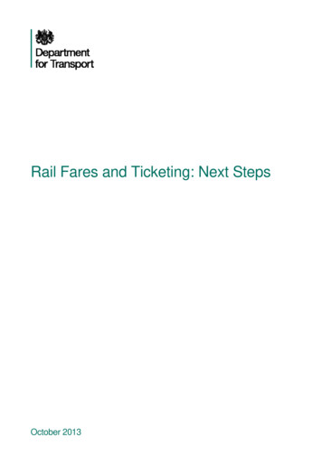
DellEMC Enterprise Systems Rail Sizing and Rack Compatibility MatrixThe Generic mounting interface encompasses all other mounting interfaces outside of the ones listed above. Unless indicated tobe tool-less, tools are required for installation.Rail types - System Installation MethodDrop-in/Stab-in rails are a feature rich rail solution that allows a system to be fully extended out of the rack for service and theuser has the option to install the system into the rail using a drop-in method like the ReadyRails sliding rails, or a stab-in methodlike the ReadyRails static rails. Drop-in/Stab-in rails support CMA or SRB applications. CMA and SRB applications must bedetached in order to remove the inner member from the rails.A “drop-in” design means that the system is installed vertically into the rails by inserting the standoffs on the sides of the systeminto the “J-slots” in the inner rail members with the rails in the fully extended position. The recommended method ofinstallation is to first insert the rear standoffs on the system into the rear J-slots on the rails to free up a hand and then rotatethe system down into the remaining J-slots while using the free hand to hold the rail against the side of the system.A “stab-in” design means that the inner (chassis) rail members must first be attached to the sides of the system and theninserted into the outer (cabinet) members installed in the rack. For systems that are 2U and larger, it is recommended that twopeople perform this operation.Scan the QRL code for documentation andtrouble-shooting information regarding theinstallation procedures for Drop-in/Stab-in railtypes.Sliding rails allow a system to be fully extended out of the rack for service. Most sliding rails support Cable Management Arms(CMAs) which enable the system to be extended out of the rack without disconnecting data/power cables at the rear of thesystem.Unless otherwise indicated, all sliding rails are drop-in sliding rail designStatic rails typically do not support the ability to service the system in the rack and are not compatible with the CMA. However,they do offer more flexibility in the types of racks and installations supported. Generally, there are two types of static rails:stab-in static and L-bracket static.Stab-in static rails require the inner (chassis) rail members must first be attached to the sides of the system and then insertedinto the outer (cabinet) members installed in the rack. For systems that are 2U and larger, it is recommended that two peopleperform this operation.L-bracket static rails do not support the ability to fully extend a system out of the rack into a service position. These railstypically are not compatible with cable management solutions unless otherwise indicated. Typically, equipment supported by Lbracket are customer serviceable from the front or rear of the rack.3
DellEMC Enterprise Systems Rail Sizing and Rack Compatibility MatrixCable Management SolutionsTo help manage the numerous cables associated with rack-mounted servers, a Cable Management Arm (CMA) or Strain Relief Bar(SRB) can be used. An optional CMA is offered with most sliding rails. CMAs attach on either the right or left side without tools.Cable management arm (CMA) is a cable management accessory which connects to the rails behind the system. It allows a fullycabled system to be extended out of the rack into a service position.Strain relief bar (SRB) is a cable management solution, which in most cases, attaches to the back of the rails via the strain reliefbar brackets. Cables from the back of the chassis are placed across the top of the SRB and secured by straps.SRBs are offered for select systems as an optional method for managing cables at the rear of the system due to the potential of acable bundle size that exceeds the capacity of the CMA. The rail depth with a SRB is significantly less than that of a CMA, whichin many cases, enables fitment of the rails in shallow racks. Cable service loops are required for systems on sliding rails to fullyextend out of the rack for service.Note that using a CMA or SRB with a deeper system may interfere with access to power distribution units (PDUs) in certain racks.If a configuration does not require CMA support, then the outer CMA mounting brackets can be removed from some of the slidingrail kits to reduce the overall length of the rails and eliminate potential interference with rear-mounted PDUs or the rack reardoor.Backwards compatibilitySome systems may offer backward compatibility with the rail kits from previous-generation systems. This is not always possible,because changes to chassis features, dimensions or weight can prevent older rail kits from being used with newer systems.Please refer to Table 1 for cross-generational compatibility of DellEMC servers and rails.Table 1.DellEMC server rails compatibility chartBackwards compatibility with 14th generation rails/CMAs15th GenerationproductSliding railsCMAStatic railsR6515 R6525X XR7515 R7525 Backwards compatibility with 13th generation rails/CMAs14th GenerationproductSliding railsCMAStatic railsR240N/AN/A R340X R440X R540/R540xd 4
DellEMC Enterprise Systems Rail Sizing and Rack Compatibility MatrixR640 R740/R740xd R740xd2N/AN/AN/AR840/940xaXXXR940X N/AC4140N/AN/A C64xxN/AN/A T440X N/AT640 N/ABackwards compatibility with 12th generation rails/CMAs13th GenerationproductSliding railsCMAStatic railsR230N/AN/A R330 R430 R530 R630 R730/R730xd R830 R930 N/AT330 N/AT430 N/AT630X N/ABackwards compatibility with 11th generation rails/CMAs12th GenerationproductSliding railsCMAStatic railsR220N/AN/A R320 R420(R210 II) R520 R620XXXR720/R720xdXXXR820XXN/AR920XN/AT320 (T610) (T610)N/AT420 (T610) (T610)N/A N/AT620X - CompatibleX – Not compatible5
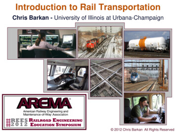
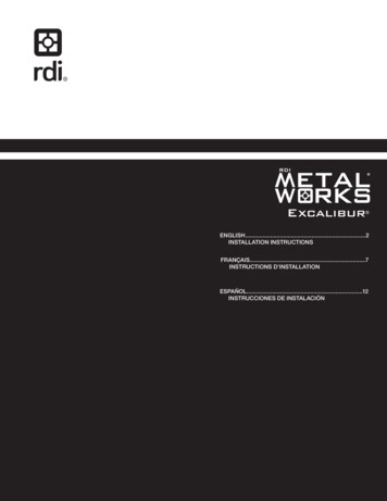
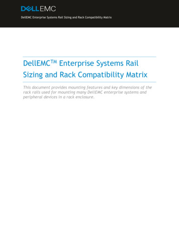
DellEMC Enterprise Systems Rail Sizing and Rack Compatibility Matrix*Only with the previous generation sliding railSelf-Adjusting Slide FeatureFor many 1U and 2U systems, rails have been standardized with a slim design that holds a wide system chassis to accommodatemore features and functions. They also have a self-adjusting slide feature that accommodates different depths of systems,offering compatibility across multiple platform models. Refer to Figure 3 for an illustration of how the self-adjusting slidefeature works.Figure 3.Self-Adjusting Slide FeatureThe rail adjustability range when the rails are installed in a rack is the same regardless of system depth since the feature is notutilized until a system is installed. If the system being installed in the rails requires this feature, the minimum rail adjustabilitylimit is increased by the amount of travel the slide body needs to slide back to support the system. The minimum railadjustability limit is documented in the resources listed at the end of this notice.Users who have systems that utilize the feature might observe a slight amount of additional resistance from a spring in each railwhen the system is almost completely installed in the rack. For most rails, the instance when the resistance is observed iswithin the final 55 mm of translation before the slam latch is engaged with the rail.The rail slide-adjusting feature can be found on both sliding and drop-in/stab-in
about the Server System Infrastructure (SSI) Specification for Computer Server Cabinet Enclosures & Racks, see the SSI Forum at ssiforum.org. Figure 1. Top view of right front EIA mounting flange Some third-party racks may not meet this requirement, and although DellEMC has made extensive efforts to accommodate as many third-party racks as possible, it is not feasible to provide a solution for .