Transcription
Staying Home Corporation2501 Anaconda RoadHarrisonville, MO 64701816-380-2427www.stayinghome.comModel SL19 Installation ManualJune 25, 20191
Preliminary ChecksInstallation Site Requirements115 VAC, 60 Hz, 3-wire grounded outlet within 6' of the top of the staircase.* Some states may require dedicated outlet.Stair angle between 25 and 45 .Indoor installation.Included with ShipmentAluminum track with gear rack and splice bars(4-6) Track mounting bracketsChassis(2) Plastic camsTools RequiredSet of nut driver bitsSet of screwdrivers (phillips)Tape measure3/8" reversible drill w/8" extensionFootrestAllen wrenchesSeatBattery Charger with 6’ cordPortable band saw or hack saw(for cutting stock track)Small levelHeader coverCombination wrench (7/16” & 1/2")Upper and lower track end capsTools to remove handrail if interferes(2) Wireless call/send key fobsSmall parts bagInstallation ManualOwner's Manual2with the travel of the stair lift
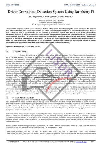
Typical ComponentsFolding ArmrestsUnit Controlunder ArmrestFolding SeatLimit CamManual LoweringAccessTrack BracketChassisFolding FootrestExtrudedAluminum TrackSafety PanOptional Key SwitchLED DiagnosticIndicatorAccess Panel toBatteries, Etc.Circuit Breaker / Reset SwitchInstall Switch3
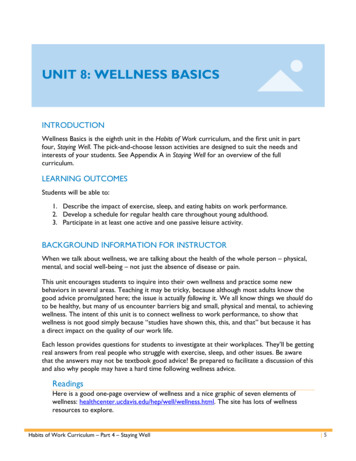
Underside of ChassisTravel Cable insideEnergy ChainUpper Limit SwitchFinal Limit SwitchOverspeed GovernorPinion GearDrive Pinion GearLower Limit Switch4
Identify Track PiecesRed paint on the end of the gear racks indicatesthat end has been precision machined. Onlybutt-up the ends of gear racks that are red. Ifthe end is not painted, it must be put towardthe end of the track.Upper TrackLower Track60" Gear Rack5
Installation Procedures for Stock UnitsTrack Installation: Track and rack should be cut before installing them on the staircaseTracks are packaged in individual boxes. You will generally have 2-3 sections of track with steel gearrack, (4-6) track mounting brackets located in a small parts box located in seat box, and 1-2 sets ofsplice bars already pre-mounted on the track.Note: The upper and lower ends of the track sections are marked top & bottom. The gear rack is alreadyinserted in the gear rack channel of the track.Look up the stairs and determine if the track is to be installed on the left side or right side.The gear rack should always be located on the right side of the track regardless of which side of thestairs the track is mounted.Door Jamb orObstructionMeasure the distance from the top nose of the staircase to thebottom floor and add 7” (note: be sure to verify clearance fromtop nose to any obstruction at the top such as a door or doorframe that would cause the chair to hit or block the seat fromswiveling.) It may be necessary to ramp the track away fromthe obstruction, consult factory for assistance if needed.Cut the track at the top, leaving the factory cuts at all othersections. Cut the gear rack flush with the top of track.6
Left HandInstallationRight HandInstallationGear rack is always onthe right side as you lookup from the bottomApply a light coat of lithium grease on the gear rack and vertical sides of the track .7
Splice Track Pieces TogetherCheck the edges of the outside C-channels for rough edges. If there are any burrs, file them off beforesplicing the trackPosition the splice bars so they are half way inserted into one track.Tighten the set screws in the bars.Tap the large end of the 3/16" pin half way into one of the tracks.Slide the other track onto the splice ensuring that the track pieces align on all sides.Tighten the remaining set screws to lock everything together. Run your finger over the outer edges ofthe tracks to assure there are no significant edges protruding. If there are, separate the track slightlyand realign as required to obtain a smooth transition between the track channels.3/16" Splice PinSplice Bars8
Secure the Track to the Stair TreadsWhen the track is installed, there should be a 1" gapbetween the underside of the track and the stairnosings and 1/4" to 1/2" off the lower landing floor.The track should be at least 4" away from the wallor other obstruction.1"1/4" to 1/2"Install rail brackets by loosening the screws andsnapping each bracket edge into the slot or slidethe brackets on from the top of the rail. The railbrackets are designed to lean the track toward thewall to offset the weight of the unit and user,therefore, the nuts on brackets should be on thestaircase side (toward the middle of the staircase).Place one bracket on first tread, one on the toptread, and one bracket immediately above andbelow each splice. Then use the other brackets tosupport any section of track left unsupported andmeasuring greater than 48".Bracket fitsinto SlotNuts go toward middleof staircaseFasten each bracket to the treads with (4) #14 X2" hex head lag screws.9
Insert the Chassis into the TrackRemove the upper most section of gear rack to allowyou to slide the chassis into the track easily.Glide BlocksEnsure the glide blocks and shim spacers are properlyinstalled on the chassis axles. One shim goes ontoeach axle on the gear rack side only. The oppositeside does not need shims.Failure to have the proper shims in place willcause the pinion gear not to engage in the gearrack properly.The chassis can now be inserted into the top end of thetrack.Feed the travel cable/energy chain inside the track.Make sure the energy chain does not snap apart.1 ShimNo ShimFlip the red RESET/OFF switch to the RESET position. The lift will beep and is now ready to be rundown onto the gear rack using the black INSTALLATION SWITCH on top of the chassis.Run the chassis down the track to the lower limit.Replace the top piece of gear rack in the track.10
With the chassis parked at the bottom limit, slide the energy chain/travel cable down along the inside ofthe track, beneath the gear rack, until there is a small loop under the chassis, beyond the point of wherethe travel cable is attached to the chassis.2-Conductor CableChain Mounting BracketEnergy Chain is positionedunderneath the Gear RackChassis and Trackshown transparentAttachment point of Chain of thebottom side of the ChassisLoopAdjust position of travel cable so there is asmall loop in the Chain.With the chain in position, fasten the chainmounting bracket to the track with (2) self-drilling screws.11
Place the upper limit cam inside the track and secure by tightening the phillips head screw.Place the end plate onto the end of the track whilerouting the travel cable through the slot in the bottom of the end plate. Tighten all (6) set screws inthe end plate.End CapLimit CamTighten the gear rack compression screw.Connect the travel cable to the charger.Plug the charger into a 120V outlet.Gear RackCompression ScrewEnd PlateLoosen the (4) socket head screws on thesides of the chassis (2 on each side).Socket HeadScrewsRemove the front cover from the footrestassembly (two phillips head screws).Front CoverPhillips HeadScrews12
Place the footrest assembly onto the two sockethead screws on the chassis. Use the keyhole patternthat offsets the footrest assembly toward the topend of the chassis.FootrestAssemblyConnect the wire harnesses between the chassis andfootrest assembly.Level the footrest and tighten the (4) socket headscrews (2 in front and 2 on back). Note that the ETLlisting is valid only when the track installed at maximum angle of 45 .WireHarnessConnect the wire harness from the RF receiver tothe mating connector on the backside of thechassis. Tuck the excess wiring into the openingin the chassis and mount the RF receiver to thechassis with the adhesive foam tape.AntennaeAdjust the position of the antennae as necessary.Wire HarnessThe swivel stop is factory set for a left-hand unit. If thelift is installed on the right-hand side of the staircase,move the seat swivel stop screw to the opposite hole ontop of the footrest assembly.RFReceiverSeat Swivel Stop Screw(Shown in LH position)RHpositionPlace the plastic thrust washer onto the swivel pin.Swivel PinThrust Washer13
Place the seat assembly onto the swivel pin. Itmay be necessary to lubricate the swivel pin.Verify the seat swivels the proper direction.Route the wire harness from the seat controlthrough the hole in the back of the footrest vertical plate and connect to the mating connector.Replace the front cover.Turn on the red RESET/OFF switch to power upthe chassis located on the top of chassis.The lift can now be operated by the unit controland the wireless key fobs.FootrestVertical Plate14Route SeatHarness thru hole
RF Remote Call-Send ControlsThe two key fobs (transmitters) have been factory programmed.If you are installing two lifts in the same home, it is not necessary to change the program. However, twolifts cannot be operated from the remote fobs at the same time. Each transmitter and receiver is uniqueand has its own rolling code.If a key fob needs to be programmed:1. Press the program button on the RF receiver 5 timesuntil the letter A is displayed. There should now be aslow flashing dot on the display.2. Press and hold either button on one of the transmittersand then release when the dot flashes faster.3. Repeat step 2 for each additional transmitter.After the last transmitter is programmed, the LED displayRF Receiver #74033AntennaeKey Fob Transmitter#74034LEDDisplayProgram Button15
AUDIO/VISUAL STATUS INDICATIONSThe lift is equipped with a chassis mounted 3-color LED display light to indicate the operating condition of the lift. Accompanying this is an audible alarm that will sound accordingly.STATUS LIGHTAUDIBLE ALARMCONDITIONRED-YELLOW-GREEN1 Second beepPower-up CycleSOLID GREENNoneReady to OperateYELLOW BLINK1/4 Second beep(30 Seconds)Batteries are not being charged(Beeping repeats every 10 minutes )YELLOW PULSE1/2 Second beep(5 Minutes)Low Battery Voltage (under 22.5 volts)2 YELLOW FLASHES1/2 Second beepSeat Swivel Latch Sensor3 YELLOW FLASHES1/2 Second beepFootrest Obstruction Sensor2 RED FLASHES*3 Second beepSensor Fault (2 or more sensors engaged)3 RED FLASHES*3 Second beepFinal Limit4 RED FLASHES*3 Second beepTravel Timeout (Motor running for more than 2-1/2minutes)YELLOW SOLID(30 SECONDS)1/2 Second beep(30 Seconds)Overload (Over 22 amps for 3 seconds)RED SOLID(3 SECONDS)3 Second beepKey turned off while traveling( Optional)OFF (SLEEP)*NoneVery Low Battery Voltage (Under 20.5 Volts for 5minutes)FLASH 2 per secondBLINK 1 per secondPULSE 1 per 10 seconds*Requires power to be cycled OFF/ON.16
Completion ProceduresSERVICE LINE 877.378.4275(Mon-Fri 8:00 – 5:00 CST)Completion ChecklistThe following features must be verified as operational before the stair lift can be released for use:Upper and lower limits: Verify the lift stops automatically at the top and bottom of the track.Charger: Verify that the light on the charger changes from green to amber when the lift is running.Running Clearance: Verify the lift clears all obstructions.Unit Control: Verify control functions in both directions.Call/Send Remotes: Verify both call/send controls operate the lift up and down in the appropriate direction.Track:Important: Top Track End Plate: It is imperative the 6 small set screws under the top track end plate are very tight.Important: Lower Track End Plate: It is imperative the 6 small set screws under the lower track end plate are verytight.Track Mounting Brackets: Verify all track mounting brackets are securely attached to the stair treads, thetrack and at the pivot points.Track Splice: Verify track joints are smooth and free of burrs and gaps.Verify the rack tension screw is tight.Verify chassis gear and rack is tight and no excess play.Verify the gear rack is lubricated with lithium or other all-purpose grease (tube of lubricant is provided)Verify the top track cover is securely fastened to the track.Verify the inside of the track is free of foreign objects.Footrest:Verify the footrest is level.Verify the footrest clears all stair nose.Verify the lift stops when the footrest runs into an obstruction in the up direction.Verify the lift will run down while the footrest is obstructed.Verify the footrest folds up and stays in the up position.Seat:Verify the seat is level and securely fastened.Verify seatbelt & buckle are secure and function.Verify the seat swivels toward the upper landing and locks into position.Verify the lift will not operate when the seat is not locked in the riding position.Verify the seat will fold up and stay in the up position.Verify both arms will fold up and stay in the up position.Clean Up: Verify the stair lift has all grease, dirt, etc. cleaned off.Before leaving the jobsite:Clean up work area.Assist customer on how to use the unit and ride it properly.Demonstrate proper operation, seatbelt use, lubrication and maintenance procedures to the user of the lift andother family members at the residence.Give customer a copy of the Owner's Manual for reference. Please take time to insert your business card orwrite your company name, address and telephone number inside the Owner's Manual in the area provided.17
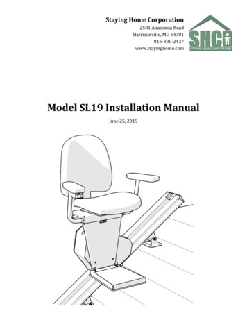
82930ORGKEY SWITCHRF RXYELLOWYELLOWBLUEBLUEYELLOWREDN.O.24V4321INSTALL CONTROLYELLOWGRAY43211234DNUPGREENGREENUP LIMITN.O.STATUSLIGHTREDYELLOWBLUEBLUEBLUE6SEAT CONTROLN.O.N.C.DNUPSWIVEL SEATREDREDFINAL LIMITUP FOOTREST58765DIAGNOSTIC LED- SOLID GREEN - ALL SYSTEMS NORMAL- AMBER BLINK - 1/4 SECOND BEEP FOR 10 MINUTES, BATTERIES NOT BEING CHARGED- AMBER PULSING - LOW BATTERY VOLTAGE- 2 AMBER FLASHES - SEAT SWIVEL LATCH SENSOR- 3 AMBER FLASHES - FOOTREST OBSTRUCTION UPHILL- 2 RED FLASHES - TWO OR MORE SAFETY CIRCUITS OPEN- 3 RED FLASHES - FINAL LIMIT CIRCUIT OPEN- 4 RED FLASHES - TRAVEL TIMEOUT- 5 RED FLASHES - OVERSPEED DEVICE- SOLID AMBER - OVERLOAD- SOLID RED - KEY SWITCH TURNED OFF DURING N8RED120VAC24VDC2AMP34THE INFORMATION CONTAINED IN THISMATERIALDRAWING IS THE SOLE PROPERTY OFSTAYING HOME CORPOTATION. ANYREPRODUCTION IN PART OR AS A WHOLE FINISHWITHOUT THE WRITTEN PERMISSION OFSTAYING HOME CORPORATION ISPROHIBITED.DO NOT SCALE DRAWINGINTERPRET GEOMETRICTOLERANCING PER:DIMENSIONS ARE IN INCHESTOLERANCES:FRACTIONAL 1/16ANGULAR: 0.5 ONE PLACE DECIMAL0.1TWO PLACE DECIMAL0.01THREE PLACE DECIMAL 0.005UNLESS OTHERWISE SPECIFIED: 12VDC-WHITEBLACK 12VDC-PROPRIETARY AND CONFIDENTIALDN LIMIT430-PIN CONNDATE54103SCALE: 1:1 WEIGHT:BSIZE DWG. NO.AREVSHEET 1 OF 1WIRING DIAGRAM - SL19COMMENTS:JBBYStaying Home Corporation2501 Anaconda RdHarrisonville, MO ITLE:JBNAMEB BK K1 2CONTROLLERM M2 110/24/2018DATE1MFG APPR.ENG APPR.CHECKEDDRAWNB B- SREV.2ABCD
Model SL19 Installation Manual June 25, 2019 Staying Home Corporation 2501 Anaconda Road Harrisonville, MO 64701 816-380-2427 www.stayinghome.com. 2 . with the travel of the stair lift. 3 Typical Components Folding Armrests Track Bracket Folding Footrest Folding Seat Safety Pan Limit Cam Extruded Aluminum Track Manual Lowering Access