Transcription
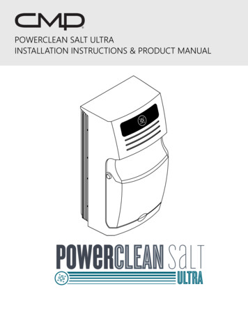
POWERCLEAN SALT ULTRAINSTALLATION INSTRUCTIONS & PRODUCT MANUAL
TABLE OF CONTENTSCongratulations on your purchase of a Powerclean Salt Ultra. You have made a wise decision and will benefit from yourchlorinator for many years to come. Please read through the entire manual before installing your new unit. Your chlorinatormust be installed and operated as specified.A. Safety Instructions & Precautions. 3B. System Sizing. 6C. Installation Procedure. 71. Required for Installation. 72. Installation Location. 73. Control Center Installation. 84. Electrical Installation. 85. Generator Cell Installation.106. System Start-up & Balancing.10D. System Operation. 121. How the Chlorinator Works.122. Salt Requirements.123. Control Center Operation.134. Cold Weather Operation/Winterization .145. Cell Maintenance: How and When to Clean Your Cell.14E. Troubleshooting. 16F. Water Care General Guidelines. 19G. Parts List. 20IMAGES & TABLES IN THESE INSTRUCTIONSpage 6SIZING CHARTpage 6FLOW RATE VS HEAD LOSS CHARTpage 8INSTALLATION LOCATION DIAGRAMpage 9BOTTOM OF CONTROL CENTER IMAGEpage 9WIRING BLOCK DIAGRAMpage 10CELL INSTALLATION EXAMPLE DIAGRAMpage 11WATER BALANCE CHARTpage 11SALT ADDITION CHARTpage 13OPERATION PANEL IMAGEpage 15CELL CLEANING WITH TOOL IMAGE2
A. SAFETY INSTRUCTIONS & PRECAUTIONSIMPORTANT SAFETY INSTRUCTIONS.READ AND FOLLOW ALL INSTRUCTIONSWARNINGTo reduce the risk of injury, do not permit children to use this product unless they are closelysupervised at all times.WARNINGRisk of Electric Shock. Connect only to a grounding type receptacle protected by a ground-faultcircuit-interrupter (GFCI). Contact a qualified electrician if you cannot verify the receptacle isprotected by a GFCI.NOTICEWARNINGCAUTIONDo not bury cord. Locate cord to minimize abuse from lawn mowers, hedge trimmers, and otherequipment.To reduce the risk of electric shock, do not use extension cord to connect unit to electric supply;provide a properly located outlet.[For swimming pool pumps with or without a maximum 3-foot (0.91-m) cord] This chlorinatoris for use with permanently installed pools and may also be used with hot tubs and spas if somarked. Do not use with portable pools. A permanently-installed pool is constructed in or on theground or in a building such that it cannot be readily disassembled for storage and reassembledto its original integrity.CAUTIONThis product can form hazardous gas if not installed or operated correctly.WARNINGAlways follow all local building and electrical codes.SAVE THESE INSTRUCTIONSELECTRICAL HAZARD All Powerclean Salt systems are shipped from the factory wired for 220 Volts. To reduce risk of electrical shock make sure all power to pool equipment area is off prior to any installation or removal ofPowerclean Salt System components. Immediately replace damaged Control Center cord. Do not bury cord. Locate cord to minimize abuse from lawn mowers, hedge trimmers and other equipment. Severe shock or injury will likely occur as a result of drill or drill cord coming in contact with water. Never allow electric drillor cord to come in contact with water. Only plug drill into a Class A (5 Milliampere Trip) protected Ground Fault CircuitInterrupter (GFCI) in accordance with the National Electrical Code Section 680 (USA ONLY). Please see your drill owner’smanual for further safety precautions. Install the Control Center at least 10 feet from the inside walls of a pool to prevent any possibility of the unit coming incontact with water. The Powerclean Salt Chlorinator has been designed with an internal electronic flow sensing tab. This device automaticallyswitches the power to the electrolytic cell “OFF” when the water through the cell stops. To prevent cell damage and/orpersonal injury, do not in any way interfere with this system which has been designed for your protection.3
A. SAFETY INSTRUCTIONSCHEMICAL USE HAZARD To avoid personal injury when working with pool chemicals, always wear rubber gloves and eye protection, and work in awell-ventilated area. Use caution when choosing a location to open and use chemicals as they may damage any surfaceto which they come in contact. The addition of certain chemicals can reduce the effectiveness of chlorine. Always make sure that proper residual chlorinelevels are maintained to avoid personal injury. This product produces chlorine. Individuals with any type of chlorine sensitivity should take the appropriate precautions toavoid injury or illness.WARNINGNOTICEWARNINGWARNINGIMPORTANT SAFETY INSTRUCTIONS PERTAINING TO RISK OF FIRE, ELECTRIC SHOCK, OR INJURYTO PERSONS. READ AND FOLLOW ALL INSTRUCTIONS. Failure to follow safety warnings andinstructions can result in severe injury, death, or property damage.Attention Installer: This manual contains important information about the installation, operationand safe use of this product. Before installing this product, read and follow all warning notices andinstructions which are included. This information should be given to the owner and/or operator ofthis equipment.To reduce the risk of injury, installation and service should be done by a qualified Pool ServiceProfessional, certified electrician or authorized CMP representative.In order to comply with UL1081 Section 53.5 and UL1795 (Hydro-massage bathtubs) Sections 21.1,59.5 and 63.1 and some local electrical codes; “connect only to a circuit that is protected by aground fault circuit-interrupter (GFCI).” Such a GFCI should be provided by the installer and shouldbe tested on a routine basis. To test the GFCI, push the test button. The GFCI should interruptpower. Push the reset button. Power should be restored. If the GFCI fails to operate in this manner,there is a ground current flowing, indicating the possibility of an electric shock. Do not use thesystem. Disconnect the unit and contact a qualified service representative before using.PREVENT CHILD INJURY AND DROWNINGTo reduce the risk of injury; do not permit children to operate this product. Do not let anyone, especially small children,sit, step, lean, or climb on any equipment installed as part of your pool’s operational system. Unless otherwise stated, ALLcomponents of your pool’s operational system should be located at least 3 feet from the pool so children cannot use theequipment to gain access and be injured or drown.EQUIPMENT WATER PRESSURE HAZARDAlways turn pump off prior to installing or removing the Electrolytic cell. Your pump/filter is operated under pressure and thepressure must be released before you begin work. Please see your pump/filter owner’s manual for further instructions. Toavoid cell damage, water pressure in the cell must not exceed 75 PSI. Do not operate electrolytic cell without proper flow orwater circulation. A build-up of flammable gases will result in hazardous conditions.4
A. SAFETY INSTRUCTIONS & PRECAUTIONSCAUTION – FAILURE TO HEED THE FOLLOWING COULD CAUSE DAMAGE TO POOL EQUIPMENT OR PERSONAL INJURY The Powerclean Salt Ultra must be installed and operated as specified in the owner’s manual.Power to the Powerclean Salt Ultra should be turned off before unplugging the Electrolytic cell from the cell housing, orpower supply, to prevent cell damage and low voltage sparks. Scratching or bending plates in the cell housing will reducecell life.DO NOT use any type of lubricant on the O-ring. It is, however, imperative that the O-ring (and the channel it seats into)be kept clean, in order to make a strong seal.High water temperatures above 104 degrees (40 degrees C) or direct sunlight can cause the cell housing exterior plasticto discolor. This is not a warranty claim.Follow installation instructions on page 7 for location and mounting of the Control Center.Visibly inspect the cell frequently to check and prevent the accumulation of pooldebris that (for any reason) may have bypassed the pool filter.Direct sunlight can cause the control center cover to discolor. This is not a warranty claim.The Powerclean Salt Ultra must be installed by a qualified pool professional or certified electrician. If you have any questionsor need assistance in finding a qualified installer, please contact our tech support team at 1-800-733-9060 or emailsupport@c-m-p.com.5
B. SYSTEM SIZING REFERENCERESIDENTIAL SIZING CHARTCELL SIZEPOOL SIZE STANDARDPOOL SIZE HIGH DEMAND*CHLORINEPER DAY320/320EXT20,000 GAL14,000 GAL0.78LB540/540EXT40,000 GAL28,000 GAL1.35LB760/760EXT60,000 GAL43,000 GAL1.88LBTABLE 1 - SIZING CHART* Correct sizing of a chlorine generator is subject to the specifications of each body of water, and should be carefullyevaluated for best results. Where heightened chlorine demand exists due to warmer climates, humidity, high bather load,water features and other environmental factors, the maximum pool size should be reduced by at least 30%.When modifying any plumbing system, it is important to evaluate the total head loss, and any impact that head loss may haveon the design of an existing plumbing system. The following chart will give specific head loss for the Powerclean Salt Cell. Ifyou have any questions, please contact our tech support department.DESIGNED FLOW RATEGPMACTUAL HEAD LOSS20%20.20 Ft Water40%40.41 Ft Water60%601.54 Ft Water80%802.28 Ft Water100%1003.71 Ft WaterTABLE 2 - FLOW RATE VS HEAD LOSS6
C. INSTALLATION PROCEDURE1. REQUIRED FOR INSTALLATIONYour Powerclean Salt Ultra Chlorinator includes the following:1 Control Center1 Ultra Style Cell Housing1 O-Ring1 Jumper Wire1 Electrolytic Cell with Cord and Cap1 Mounting Bracket1 Cleaning Tool1 Owner’s Manual2 Union Nut Tail-piecesThe following items will also be required to install the Powerclean Salt Ultra system:ScrewdriverLevelHacksaw or PVC CutterWire Stripping ToolElectric Drill8AWG Copper Bonding WireMounting ScrewsINSTALLING THE CONTROL CENTER WARNING! When using electrical products, basic precautions should always be followed:be sure to read and follow safety instructions on pages 3 though 5.DANGERRisk of electric shock, which can result in serious injury or death. Before attempting installation orservice, make sure that all power to the circuit supplying power to the system is disconnected/turned off at the circuit breaker. Connect only to a circuit protected by a ground fault circuitinterrupter (GFCI).2. INSTALLATION LOCATIONa.b.c.d.e.f.It is recommended to install the salt cell installed as the last piece of pool equipment in line, on the return to the pool,after the heater. (See illustration 1 on next page)Installing horizontally will ensure the flow sensor remains submerged.If installed vertically, the cell cap must be on top.Always use a check valve before the cell to prevent chlorine backflow.All fittings are 2 inch Socket.NONE: Do not install on pools using a stainless steel liner or stainless steel plumbing.BELOW GRADE INSTALLATION:g. This exists when the water level of the pool is above the height of the pool equipment.h. The system should be wired to the load side of the time clock to power on ONLY when the primary pump is operating.i. If valves are not present to isolate the equipment, one ball valve should be installed on the inlet side of the cell. Thisallows the cell to be removed for cleaning when necessary.j. A one-way check valve should be installed on the outlet side of the cell. This will eliminate the possibility of having a gasbuild-up (which could cause possible cell damage.)k. CAUTION: Failure to follow proper below grade installation procedures may lead to damage to pool equipment.7
C. INSTALLATION PROCEDUREPowerclean SaltUltra CellDEL Ozoneor AOPCheck ValveOZONEINJECTEDCheckValvePlace salt at least 2ft after ozone injection.Ozone or AOP can also be installed on adedicated return linePumpFilterHeaterImage is not to scaleFrom PoolReturn to PoolIMAGE 1 - INSTALLATION LOCATION3. CONTROL CENTER INSTALLATIONa.Using the end of the cell cord as a guide, locate a suitable location for the mounting of the Control Center. The ControlCenter must be mounted on a noncombustible surface.The wall mounting bracket should be fastened to the wall at a height comfortable for operation. Screws or anchors arenot included. Make sure that the bracket is fastened directly onto concrete with the proper anchoring device or into astud in a noncombustible wall surface. Mount the bracket by installing the one screw, and then leveling the bracket, andinstalling the other screw, making sure that the mounting bracket is level and horizontal.IMPORTANT: Do not enclose the Control Center in any box.The Powerclean Salt Ultra Control Center has two mounting bolts installed at the top back of the unit: simply place thehead of the pins in the keyhole slots on the wall bracket, and allow the unit to hang freely.b.c.d.4. ELECTRICAL INSTALLATIONa.The Powerclean Salt Ultra Control Center is shipped wired for 220V. The control center can be converted to 120V in thefield by a pool professional or certified electrician; a wiring diagram for making the conversion in included with eachsystem printed on the box.The system is designed to power on ONLY when the primary pump is operating and should be wired to the load side ofthe time clock.Ground with an 8AWG bonding wire from the lug (Image 2) on the bottom of the Control Center to a grounding rod (thisis necessary to protect the integrity of the electronic systems).A complete wiring diagram is included on the next page (Image 3)NOTE: If installed with VS Pump, run chlorinator on secondary timer and sync the second timer with run time on VSPump. This ensures the system powers on in sync with the pump in low flow situations.b.c.d.e.8
C. INSTALLATION PROCEDUREIMAGE 2 - BOTTOM OF CONTROL CENTERGROUNDTIMER CLOCKSUB PANELLINEGROUND1GROUNDTIMER CLOCKSUB PANELLINE2123344120V ACCONFIGURATION220V ACCONFIGURATIONGROUNDPUMPPUMPIMAGE 3 - WIRING BLOCK DIAGRAM9
C. INSTALLATION PROCEDURE5. GENERATOR CELL INSTALLATIONa.b.Locate pool return line after the heater or filter as shown in Image 1. This is the preferred location for the cell housing.Cut and glue the vertical plumbing risers from the main plumbing into place. Install union nut and tailpiece onto pipe.Use included template to set pipe spacing. Install the cell housing to the top of the risers, making sure the cell housing islevelInstall the O-ring into the receiving channel inside the cell housing, and then slide the cell into the cell housing makingsure the key way on the black plastic base aligns with the matching key in the cell housing.Put the main cap into place and hand tighten only; be sure not to strip the threads.Connect the cell cord to the Control Center. Align the three pins of the cell cord plug with the socket on the ControlCenter bottom (Image 2) and insert the connector until it clicks in place.c.d.e.FLOWPowerclean SaltUltra CellCheckValveIMAGE 4A - HORIZONTAL CELLCheckValveFLOWFLOWFLOWPowerclean SaltUltra CellIMAGE 4B - VERTICAL CELL6. SYSTEM START UP & BALANCINGa.Balance your water chemistry according to the Water Chemistry Parameters (Table 3). Add the proper amount of salt andcirculate 24 hours before starting the Powerclean Salt Ultra.Start system at the 75% Chlorine Output level and operate normally. For the first two weeks, test the water every 2-3 daysfor proper chlorine residual levels. Raise or lower the Chlorine Output by pressing the output control arrows as needed(see operation instructions on page 12), according to your test results. ( See section D-3 for details)If Chlorine Output percentage setting is 100%, and chlorine residuals are still below the 1-3 PPM range, increase theoutput to BOOST, see Troubleshooting on page 16.The rule of thumb for daily run time of the Powerclean Salt Ultra system is 1 hour of operation for every 10 degrees ofambient temperature (i.e. 90 degrees would equal 9 hours of run time).Once chlorine output percentage setting is set, output should only be adjusted for increased chlorine demand situations.b.c.d.e.10
C. INSTALLATION PROCEDUREMEASUREMENTFREE CHLORINEpHTOTAL ALKALINITY (TA)CYANURIC ACID / STABILIZERCALCIUM HARDNESSPHOSPHATESSALT RESIDUALRECOMMENDED LEVELDETAILS1.0 - 3.0 PPMRecommended level for residential pools to keep chlorine at a properrange for sanitization7.2 - 7.6High pH reduces sanitizer efficiency. Low pH damages pool surfaces andirritates skin and eyes80 - 100 PPMProtects pH and prevents rapid pH "bounce"30 - 50 PPMProtects chlorine from destruction by sunlight. Must be added manuallywith salt chlorine systems200 - 400 PPMExcess calcium can increase scaling problems. Low calcium (soft water)can damage surfacesZEROCan deplete free available chlorine4,000 - 4,500 PPMIdeal level for chlorine production. Powerclean Salt systems will operateat 3,000 - 35,000 PPMTABLE 3 - WATER BALANCEPOUNDS OF SALT PER GALLON REQUIRED TO REACH 4,000 - 4,500 PPMPOOL SIZE (GALLONS)CURRENT POOL SALT CONCENTRATION (PPM)800010000 12000140001600018000 20000 220002400026000 28000 30000 32000 34000 36000 38000 kokokokokokokokTABLE 4 - SALT ADDITION CHART11
D. SYSTEM OPERATION1. HOW THE CHLORINATOR WORKSAt System Start Up the pool water should have a 4000-4500 ppm salt residual. Common salt (sodium chloride) is made up oftwo elements, sodium and chloride. As part of the daily filtration cycle, the pool water is passed through the Powerclean SaltUltra electrolytic cell to produce chlorine, which is instantly dissolved into the water.The chlorine destroy bacteria, viruses and algae. When the chlorine is spent it reverts back into dissolved salt, restarting thecycle.WATER PREPARATION AND TIPS ON WATER CHEMISTRYPool water that is not maintained properly will cause damage to the electrolytic cell and possibly void the warranty of thecell. Properly balancing pool water chemistry is the most important aspect of maintaining a swimming pool. Pool water mustbe tested regularly in order to properly maintain its chemical balance. In accordance with The Association of Pool and SpasProfessionals (APSP) standards, we recommend the following water balance conditions be maintained on an ongoing basis toprotect the pool finish and equipment, and ensure a pleasing appearance of the water. The Powerclean Salt Ultra systems arewarranted to operate properly only if these conditions are met.2. SALT REQUIREMENTSa.The Powerclean Salt Ultra operates best with a salt range of 4,000 - 4,500 ppm. The cell will continue to operate with aminimum of 3,000 PPM and up to 35,000 PPM without any adverse effects to the unit.NOTE: HIGH salt level above 8,000 PPM may cause corrosion problems with metallic fixtures, light rings, ladders andhandrails.Only pool grade salt should be used. This can be purchased at pool supply stores and most hardware outlets. NEVER usesalt that contains iodine or anti-caking agents like YPS, which can cause some discoloration of fittings and pool surfacefinishes.NOTE: Do not use rock salt due to its high levels of impurities.b.c.d.WHEN TO ADD SALTe. Salt level should be checked monthly. The salt level should never be allowed to fall below 3,000 PPM.f. Salt level is lowered through dilution (adding fresh water or rainfall), water splashed out of the pool and/or backwashingthe filter. Salt is not lost through evaporation. If the salinity level drops below the recommended salinity range, use Table 4on Page 11 to determine the amount of salt that has to be added to obtain the proper salinity level.g. NOTE: The Powerclean Salt Ultra will stop generating and the Power light will flash when one of the following conditionsexist: cold water (under 60 ), low salt (under 3,000 PPM) or a dirty cell (see Image 4 or Troubleshooting section forinstructions on what to do when the system goes into service mode).CAUTIONDo not operate the Powerclean Salt Ultra with newly poured pool plaster. Check with the poolbuilder or remodeler for specifics on their products before you operate the Powerclean Salt Ultrachlorinator.HOW TO ADD SALT TO THE POOLh. Determine salt level as discussed above. Use Table 4 to calculate the amount of salt needed.i. Power on the pump to circulate the pool water.j. Slowly pour in the salt around the outer perimeter of the pool for quick and even distribution. To avoid clogging the filteror damaging the Control Center and pump, do not add salt through the skimmer or surge tank.k. Brush the pool bottom to distribute the salt evenly and allow water to circulate for 24 hours to dissolve completely. After24 hours, confirm salt level reading.l. Power on the Powerclean Salt Ultra system and set output percentage to desired Chlorine Output level (see BasicOperation Section)12
D. SYSTEM OPERATION3. CONTROL CENTER OPERATIONCONTROL CENTER GUIDEa. Chlorine Output Lights (A) show level of chlorine output as a percentage of system capacityb. Solid Power light (B) indicates the system is operating correctlyc. Service Light (C) indicates a system warning. See Troubleshooting section page 16d. Polarity (D) indicates direction of current; reverses every 6 hours of operation automaticallye. Press Output Controls Up or Down (E) to increase or decrease system outputf. On / Off Switch (F) controls main power to systemAEFDBCIMAGE 5 - OPERATION PANELSYSTEM POWER UPg. Engage Power switch by pressing to “On” position. As the system boots up, the lights will flash for about ten seconds. ThePower light will then remain solid; the Chlorine Output lights will display the selected chlorine output level. One of thePolarity lights will also illuminate, indicating the direction of current.h. Every six hours of system operation the polarity will change automatically, which prolongs the life of the cell andminimizes build up between the cell blades.i. If the power is interrupted (either by the pump turning off or by putting the Power switch into the off position), the systemwill automatically reset to the setting when last powered on.13
D. SYSTEM OPERATIONSYSTEM OUTPUT OPERATIONj. Once the system is in normal operation mode, increase or decrease output with the Output Controls.k. Each adjustment will be indicated at the Chlorine Output Lightsl. When in BOOST MODE (with the red BOOST light illuminated) the system will automatically operate for 72 hours of runtime, and then reduce to the 100% level. Boost Mode should be used to offset “out of the ordinary” conditions: unusualweather or extremely high bather load.m. Recommended Daily Operation: Operate the pool pump at least 1 hour for every 10 degrees of ambient air temperature.4. COLD WEATHER OPERATION/WINTERIZATIONa.In cold water conditions (below 60 F), sanitizer demand is reduced significantly. The Powerclean Salt Ultra will reduce itsrate of production with water temperatures of 59 degrees Fahrenheit and below depending on the condition of the poolwater chemistry.If the water temperature drops too low for the electrolytic cell to produce chlorine, the service light on the control centerwill light up and the cell will stop producing. This is due to the water not being conductive enough for the electrolyticprocess to take place.For colder climate regions with sustained low or freezing temperatures, the Powerclean Salt Ultra Cell should be properlydrained and winterized by a qualified pool professional.b.c.5. CELL MAINTENANCE: HOW AND WHEN TO CLEAN YOUR CELLINSPECTING THE CELLa. Visually check the cell through the clear housing while the system is operating for buildup on the electrodes and the legsattaching the electrodes to the cell base.b. If there is no buildup, there is no need to clean the cell.c. How often cleaning is required depends on the chemistry of the pool water, including the hardness of the water and pH.HOW TO CLEAN THE CELLd. IMPORTANT: Always turn off the pump prior to cleaning the cell. The pump and filter system is operated under pressure,and the pressure must be relieved before you will be able to remove the cell from the cell housing.e. Remove the cell cap (the large blue cap at the end of the clear cell housing) by turning it counter clock-wise.f. Gently pull the cell electrodes out of the housing, being careful not to damage the o-ring.g. Once the cell is removed from the housing, slide the cleaning tool between the blades to remove any calcium build-up .Also clean the legs of the electrodes.h. It is not necessary to “scrape” all build-up from the electrodes. Simply remove any build-up and clean any bridgingbetween individual electrodes.i. Only use the provided tool to clean the cell. Never use a metal tool to clean.j. NOTE: THERE IS NO NEED TO USE ACID FOR THIS PROCESS.k. Take the o-ring out of the cell housing, and remove material or debris from it. Once you have cleaned the o-ring, use atowel or cotton swab to wipe out the channel in the cell housing that the o-ring seats into.l. Replace the o-ring to its channel in the cell housing (DO NOT USE LUBRICANT).m. Install the electrodes into the cell housing, making sure not to disturb the O-ring.n. Return the blue cap to the cell housing and hand tighten in the clockwise direction. Be careful not to over tighten.o. Re-start the pump.14
D. SYSTEM OPERATIONIMAGE 6 - CELL CLEANING WITH TOOL15
E. TROUBLESHOOTINGSITUATIONLow or no chlorine residualin poolUnable to increase chlorineproductionThe cell housing is leakingfrom the cap (bottom ofcell cap or through the cordhole)Water is leaking from thecell plug.16POSSIBLE CAUSECORRECTIVE ACTIONLow stabilizer (Cyanuric acid level inpool water).Add stabilizer to maintain 20-30 PPM perpool professional’s recommendations.Insufficient run time.Increase daily run time. Recommend 1hour of run time per 10 degrees ambienttemp.Chlorine Output percentage set toolow.Increase the Chlorine Output Level (seepage 13 ).Recent increases in weathertemperature without increasing theChlorine Output of the systemIncrease the Chlorine Output Level (seepage 13).Temporary loss of chlorine due toheavy rain, leaves, fertilizer or heavybather load, recent party, or pets usingpool.Set Chlorine Output to BOOST (SuperChlorinate) for 72 hours. Re-check- if stilltoo low, superchlorinate with outsidesource. (Take pool water sample to poolprofessional)Loss of salt due to rain or added water.Test salt level. Add salt using the chart onpage 11Low salt level (less than 3,000 PPM).System Power light is flashing/ servicelight is yellow/ solid.Increase salt level by adding salt accordingto chart on page 11.Cold water, low salt level, or cell is overcalcifiedCheck cell and clean, check saltlevel, check water temperature.O-ring may be improperly seated.Confirm that o-ring has not beenlubricated. Clean the o-ring slot of any dirtor debris. Fully seat the o-ring in into theslot before inserting the cell back into thehousing.Cell cap may be cross threaded.Unscrew cap and confirm thatthe cap screws onto the housingwithout resistance.Water is traveling through a crack inthe cell base and up the cell cord.Contact Tech Support
E. TROUBLESHOOTINGSITUATIONPower light is flashing andservice light is on.POSSIBLE CAUSEPool water needs salt.Test salt level of water. Add salt if necessary.(see chart on page 11)Cell is clogged or dirty.Check and clean cell (see page 14)Water temperature is low.Check water temp, if below 60 degrees,turn system off. See page 14 for detailsInsufficient water flow. Make sure pump is running. Check and correct all valve alignments. Dirty filter: follow filter cleaningprocedures Clea
6 b. system sizing reference residential sizing chart cell size pool size - standard pool size - high demand* chlorine per day 320/320ext 20,000 gal 14,000 gal 0.78lb