Transcription
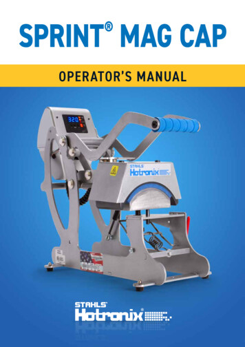
SPRINT MAG CAP OPERATOR’S MANUAL
HOTRONIX SPRINT MAG CAP Safety InstructionsWhen using your heat press, basic precautions should alwaysbe followed, including the following:1. Read all instructions.2. Use heat press only for its intended use.3. To reduce the risk of electric shock, do not immerse the heat press in water or other liquids.4. Never pull cord to disconnect from outlet, instead grasp plug and pull to disconnect.5. Do not allow cord to touch hot surfaces, allow heat press to cool completely before storing.6. Do not operate heat press with a damaged cord or if the equipment has been dropped or damaged.To reduce the risk of electric shock, do not disassemble or attempt to repair the heat press. Take it toa qualified service person for examination and repair. Incorrect assembly or repair could increase therisk of fire, electric shock, or injury to persons when the equipment is used. Power supply cord mustbe disconnected before cleaning or servicing press.7. This appliance is not intended for use by persons (including children) with reduced physical, sensory ormental capabilities, or lack of experience and knowledge, unless they have been given supervision orinstruction concerning use of the appliance by a person responsible for their safety.8. Close supervision is necessary for any heat press being used by or near children. Do not leave equipmentunattended while connected.9. To avoid burns, do not touch hot metal parts or the heated platen during use.10. To reduce the likelihood of circuit overload, do not operate other high voltage equipment on the same circuit.11. If an extension cord is necessary, then a 20-amperage rated cord should be used. Cords rated for lessamperage may overheat. Care should be taken to arrange the cord so that it cannot be pulled or tripped over.12. Keep hands clear of the upper heat press platen during lock down as the pressure may cause injury.13. Heat press should be placed on a sturdy, suitable stand at least 91,5 cm L x 60 cm W x 75 cm H.14. Work area must be kept clean, tidy and free of obstructions.2
Table Of ContentsSafety Instructions2Machine View4Operating Instructions5LED DisplayConnecting the SystemStart Up/Shut DownAdjusting SettingsElectrical Schematic5667-89Replacement Parts List10Parts Location Guide11Contact us12
HOTRONIX SPRINT MAG CAP Machine ViewCircuit BreakerLED DisplayCap HoldDown LeverPower SupplyLift Handle12V MagnetONOFFUpper PlatenPower ON/OFF SwitchLower PlatenPressure Adjustment Knob4
Operating InstructionsLED DisplayDigital DisplayTemperature IndicatorSet IndicatorTime IndicatorDecreasePressure IndicatorMode SelectIncreaseWWW.STAHLS.DE5
HOTRONIX SPRINT MAG CAP Operating InstructionsConnecting the SystemConnect the power cord into a properly groundedelectrical outlet with a sufficient amperage rating (1.1).Voltage230 volt requires a full 10-ampgrounded circuit.Extension cords should be as short as possible and not less than 12 gauge.Heavy duty cords are recommended.Circuits with less than 10 amps or other high demand equipment orappliances (especially more than one heat press machine) plugged in, shouldnot be used.1.1NOTE: If the supply cord is damaged, it must be replaced by the manufacturer,its service agent or a similarly qualified person in order to avoid hazard. UseSJT type, rated 300V for replacement.CAUTION Failure to follow these instructions will cause:1. Erratic controller functions.2. Inaccurate displays and slow heat-up.3. The circuit breaker to disengage.2.1Start Up/Shut DownLocate the packaging bolt on top of press and remove prior to turningon or operating (2.1).Locate the Power ON/OFF Switch on the side of the press, thenturn the Power Switch ON (2.2).NOTE: The Sprint Mag Cap Press is equipped with an Auto Sleep Mode. When themachine is inactive for a period of two hours, it will enter an energy saving sleep mode.To restore to normal operating mode, press any button on the display panel and allowthe heat press to return to the target temperature.62.2
Operating InstructionsAdjusting SettingsAdjust TemperaturePress the Mode Select button in the center of the Control Panel.The (SET) and (TEMP) lights located next to the display will illuminate.Press the ( ) or (-) button to raise or lower the temperature setting.The temperature can be set from 176 F (79 C) to 430 F (220 C).The LED Display will show changes as you make them.Adjust TimeYour heat press has two time settings that will allow you to set different times when atwo-hit application is required. For single-hit applications, simply set both timesettings the same.Once the temperature is adjusted, press the Mode Select button again to advance to Time #1 Mode.The (SET) and (TIME) lights will illuminate, indicating you are in Time #1 Mode.Once you have Time #1 set, push the Mode Select button again to advance to Time #2 Mode. Allthree red LED lights will illuminate indicating you are in Time #2 Mode. Select the desired time andpush the Mode Select button again to exit time settings. All lights will be off and the presswill return to PRINT mode.NOTE: Press the Mode Select button ONCE to advance to Adjust Temperature Mode. Press the Mode Select button A SECOND TIME to advance to Time #1 Mode. Press the Mode Select button A THIRD TIME to advance to Time #2 Mode. Press the Mode Select button A FOURTH TIME to return to Heat Up/Operating Mode.Turn knob clockwise to increase pressure and counterclockwise to decrease pressure.WWW.STAHLS.DE7
HOTRONIX SPRINT MAG CAP Operating InstructionsPressure ReadoutA visual Pressure Readout is located on the lower right side of the LED Display.When the handle is locked into the PRINT position, a pressure number between 0-9 will be displayed.0 indicates no pressure and 9 indicates very heavy pressure.Remember to allow for the thickness of your cap when adjusting the pressure.1 - 3 Light Pressure4 - 7 Medium Pressure8 - 9 Heavy PressureWARNING: Structural damage caused by excessive pressure is not covered under the limited warranty!PressingOnce your equipment has reached the designated temperature: Position the cap and design Lower the cap hold down lever to lock into place Pull lift handle down and begin to heat apply The automatic timing process will beginThe timer will automatically count down and lift the heat platen into the UP position when the print cycle is complete.Note: Please be aware after time is complete, gas shocks will automatically release the platen into the UP position.8
Electrical SchematicUS 120 V VERSIONUS 220 V VERSIONCE 230V VERSIONWWW.STAHLS.DE9
HOTRONIX Replacement Parts ListSPRINT MAG CAP ITEM 435363738394041424445464748515259606162636465PART NAMEPART #Control Housing, STXController Overlay, STXGrommet, 9/32” ID 3/8” ODScrew, Sheet Metal #6 x 1/2”Nut, #6-32 Hex with LockwasherScrew, Pan Phillips #4-40 x 1”Power InletPower SwitchScrew, Machine #6-32 x 1/2”Screw, Machine #6-32 x 1/4”Conduit Fitting, 1/2” Topaz Straight Twist-OnController Kit, STXNut, #4-40 with Tooth WasherController Bracket, STX MAXXTRIACScrew, Machine #4-40 x 3/8”Terminal Block, 5 Contact High VoltageProximity SwitchCircuit Breaker 5A (CAP 6x6)Handle Assembly, STX 6 & CapMagnet Bracket, STX6 & CapMagnetSteel Pin, 1/2” x 6.45”Washer, 1/2” NylonHub Cap 1/2”Steel Pin, 1/2" x 5-7/8"PVC Spacer, 1/2" x 3.30"PVC Spacer, 1/2" x 0.70"JCN - NUTAll Thread PinPVC Spacer, 1/2" x 5"Blue Foam GripShipping Bolt (Thumb Screw), 1/4"-20 x 1/2"Lift Link, STX 6x6 & CapAdjustment Spindle, STX 6x6Knob, Black Plastic 3/8"-16Bronze WasherCap Platen, Standard 3.5" x 6"Silicone Pad, Cap 3.5" x 6" BlueCap Hold DownCap Hold Down Vinyl CoverSpringGas Spring 11x15 & 6x6 & CapBase, STX 6x6 & CapScrew, Pan Phillips #6-32 x 3/4"Ball Stud 10mmNut, Hex Nylok 5/16"-18Acorn Nut 10-32Rubber FootScrew, Button Socket Head #10-32 x t 2317KIT 53-1011-232KIT 1-10731-2246KIT 011-1641-1085 Wear 11111225551ITEM #PART NAMEPART 203204205206207Nut, Nylok #8-32Heater Arm Assembly, STX CapPVC Spacer, 1/2" x 3.80"Steel Pin, 1/2" x 4.69"PVC Spacer, 1/2" x 5/8"ElectromagnetSilicone Pad, 5/16" ID x 1-3/4" OD x 1/4" TWasher, 5/16" SSScrew, Shoulder 5/16" x 1/2" w/ 1/4"-20 ThreadHeat Platen, Cap 120V/220VPin, Clevis 3/8" x 1-5/8"Retaining Clip, Rue RingScrew, SS Phillips #8-32 X 1/4"Temperature ProbeThermostat DiscScrew, SS Sheet Metal #4 X 1/4"Heat Platen Cover, CapConduit, STX MAXX Cap, 13"Washer, Plastic FinishingScrew, Flat Head Phillips #10-24 x 7/16"120V Locking Power Cord220V Power Cord230V European Locking Power CordLower Platen SpacerPlaten Lift KitQuick Change Keyway (Old Style)Screw, Machine #8-32 x 3/8” Black OxideHeater Wire (Not Shown)2-1006-56KIT 16711-21862-16721-1279KIT 211111121
Parts Location Guide24282930313945405160634846 47 Wear PartsWWW.STAHLS.DE11
CONTACT USSTAHLS’ Europe GmbHDieselstraße 6266763 DillingenGermanyTechnical Support &Customer Service 49 (0) 68 31/97 33 0Emailinfo@stahls.deWebstahls.deThis document includes multiple trademarks and describes equipment covered by manypatents that are owned by GroupeSTAHL and/or its subsidiaries. GroupeSTAHL enforcesits rights to protect these intellectual properties. 2021
three red LED lights will illuminate indicating you are in Time #2 Mode. Select the desired time and . 12 Conduit Fitting, 1/2" Topaz Straight Twist-On 1-1353 2 13 Controller Kit, STX Kit 3-6945 1 14 Nut, #4-40 with Tooth Washer 2-1006-51 8 15 Controller Bracket, STX MAXX 2-1661 1