Transcription
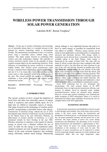
International Journal of Scientific & Engineering Research, Volume 7, Issue 4, April-2016ISSN 2229-5518655WIRELESS POWER TRANSMISSION THROUGHSOLAR POWER GENERATIONLakshmi M.K1, Reenu Varghese2Abstract— In the age of wireless technology and increasinguse of renewable energy there is a constant increase in thedemand for wireless technology which is environmentfriendly. The phenomenon incorporated in here is to transferpower using a renewable source, without using wiredmedium. This paper mainly focused on combining bothwireless and solar technologies together. This principle ofwireless electricity transfer works on the principle of usingcoupled resonant objects for the transferring electricity. If theefficiency of transmitting the power wirelessly is increasedslightly further, then wireless power transmission couldbecome a standard means for charging any electronic gadget,and also if it is by means of a renewable and clean powersource such as solar energy, it would be a cherry on top ofthe cake. The overall goal of this paper is to design andimplement a clean power generation and wireless powertransmission system.Keywords—Resonanceenergy leakage is very important because the goal is tohave as much energy as possible be transferred fromone object to another . Wireless energy transfer can beuseful in such applications as providing power to autonomouselectrical and electronic devices. This energy which istransferred can be derived from a renewable source; the bestavailable option is the Solar Energy. Solar energy isharnessed by the means of Solar Cells. The solar cells aremade of silicon crystals that have been combined with othermaterials in such a way that there are extra electrons in onepart of the cell, and missing electrons in another part of thecell. When the sunlight strikes the cell, photons in the lightknock some of the extra electrons loose from the silicon, andthey flow to the part of the cell that is missing electrons. Thisflow produces an electrical current that eventually reaches theinverter, where it gets converted into usable electricity. Theoverall goal of this paper is to design and implement a cleanpower generation and a wireless power transmission system.Every WPT technology has its own advantages anddisadvantages. The main research themes of all WPTtechnologies focus on improving the transmission efficiency anddistance. In addition, driven by industrial needs, multipletransmitters/receivers design has attracted much attention.However, several open research challenges exist, hindering thepublic acceptance of WPT technologies. Hence, it is crucial tounderstand and address these challenges for paving the way fora brighter future of the WPT ,I. INTRODUCTIONThe current scenario revolves around the depletion offossil fuels and other non renewable sources of energywhich is expensive and cannot reliable upon. So it ishigh time we shifted to renewable sources of energy.This paper focused on the technology of wireless powertransfer, incorporating a renewable source solar energy.Transmission of electrical energy without the use of wiresthat depends upon electrical conductivity was first introducedby Sir Nikola Tesla in the year 1891[1][2]. Witricity, anabbreviation of wireless transfer of electricity, is a termintroduced initially by Dave Gerding in the year 2005.Wireless electricity or witricity is the transfer of electricenergy or power over a distance without the use ofwires. In order for the energy to be transferred safelycoupled resonators are used. Coupled resonators are twoobjects of the same resonant frequency that exchangeenergy efficiently without much leakage. MinimizingII.EXSISTING METHODSIn present days transmission and distribution of power in gridis done through wired medium. One of the major issue in powersystem is the losses occurs during the transmission anddistribution of electrical power. As the demand increases day byday, the power generation increases and the power loss is alsoincreased. The major amount of power loss occurs duringtransmission and distribution. The percentage of loss of powerduring transmission and distribution is approximated as 26%.The main reason for power loss during transmission anddistribution is the resistance of wires used for grid. Theefficiency of power transmission can be improved to certainlevel by using high strength composite over head conductors andunderground cables that use high temperature superIJSER 2016http://www.ijser.org
International Journal of Scientific & Engineering Research, Volume 7, Issue 4, April-2016ISSN 2229-5518conductor[3]. But, the transmission is still inefficient. Accordingto the World Resources Institute (WRI), India’s electricity gridhas the highest transmission and distribution losses in the world– a whopping 27%. Numbers published by various Indiangovernment agencies put that number at 30%, 40% and greaterthan 40%. This is attributed to technical losses (grid’sinefficiencies) and theft [1].Any problem can be solved by state–of-the-art technology.The above discussed problem can be solved by choose analternative option for power transmission which could providemuch higher efficiency, low transmission cost and avoid powertheft. Microwave Power Transmission is one of the promisingtechnologies and may be the righteous alternative for efficientpower transmission.III. WIRELESS POWER TRANSMISSIONThe technology for wireless power transmission or wirelesspower transfer (WPT) is in the forefront of electronicdevelopment[4]. Applications involving microwaves, solar cells,lasers, and resonance of electromagnetic waves have had themost recent success with WPT. The main function of wirelesspower transfer is to allow electrical devices to be continuouslycharged and lose the constraint of a power cord. Although theidea is only a theory and not widely implemented yet, extensiveresearch dating back to the 1850’s has led to the conclusion thatWPT is possible. The three main systems used for WPT aremicrowaves, resonance, and solar cells. Microwaves would beused to send electromagnetic radiation from a power source to areceiver in an electrical device. The concept of resonance causeselectromagnetic radiation at certain frequencies to cause anobject to vibrate. This vibration can allow energy to betransmitted between the two vibrating sources. Solar cells,ideally, would use a satellite in space to capture the suns energyand send the energy back to Earth. This concept would help tosolve the major energy crisis currently concerning most of theworld. These ideas would work perfectly in theory, butconverting the radio frequencies into electrical power andelectrical power to radio frequencies are two main problems thatare withholding this idea to become reality.Wireless power transfer technology can be applied in a widevariety of applications and environments. The ability of ourtechnology to transfer power safely, efficiently, and overdistance can improve products by making them moreconvenient, reliable, and environmentally friendly. Wirelesspower transfer technology can be used to provide:-Automaticwireless charging and use of mobile electronics in car whiledevices are in use and mobile. Direct wireless powering ofstationary devices (flat screen TV’s, digital picture frames,home theater accessories, wireless loud speakers, etc.)eliminating expensive custom wiring, unsightly cables .Etc eliminating disposable batteries and awkward cabling.656IV.VARIOUS SCHEMES OF WIRELESSPOWER TRANSFERThere are many techniques which are being used to achievewireless power transfer. Some of the methods are beingdiscussed below.IV.1. WPT using Microwaves:In the transmission side, the microwave power sourcegenerates microwave power and the output power ismanaged by electronic restrain circuits[5]. The purpose ofthe tuner is to match the impedance between thetransmitting antenna and the microwave source. Theattenuated signals gets divided based on the direction ofsignal propagation by Directional Coupler. Thetransmitting antenna emits the power uniformly throughfree space to the antenna. In the receiving section, aantenna receives the transmitted power and translates themicrowave power to DC power. The impedance matchingcircuit and the filter is provided for setting the outputimpedance of a signal source equal to the rectifyingcircuit. The rectifying circuit have Schottky barrier diodeswhich converts the received microwave power into DCpower.IJSERIV.2. WPT using Magnetic Resonance:In this technique, at first we design an oscillator, whichgenerates the carrier signal to transmit the power.Oscillators are not usually designed to deliver power, thusa power amplifier is added to the oscillator to amplify theoscillating signal[5]. The power amplifier would handover the output power to the transmission coil. Next, areceiver coil is constructed to receive the transmittedpower. However, the power received in the receiver sidehave an alternating current. Thus, a rectifier is needed torectify the AC voltage. Finally, an electric load is attachedto finish the entireV. SOLAR CELLSSolar cells are devices in which sunlight releases electriccharges so they can move freely in a semiconductor andultimately flow through an electric load, such as a light bulb or amotor. The phenomenon of producing voltages and currents inthis way is known as the photovoltaic effect[6]. The fuel forsolar cells—sunlight—is free and abundant. The intensity ofsunlight at the surface of the earth is at most about one thousandwatts persquare meter. Thus the area occupied by the cells in aphotovoltaic power system may be relatively large, and its costIJSER 2016http://www.ijser.org
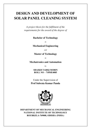
International Journal of Scientific & Engineering Research, Volume 7, Issue 4, April-2016ISSN 2229-5518must be considered in calculating the cost of the electricityproduced. The primary factor that determines whether solar cellswill be used to supply electricity in a given situation is the costper unit output, relative to that of alternative power sources, ofacquiring, installing, and operating the photovoltaic system.Solar cells are already being used in terrestrial applicationswhere they are economically competitive with alternativesources. Examples are powering communications equipment,pumps, and refrigerators located far from existing power lines. Itis expected that the markets for solar cells will expand rapidly asthe cost of power from conventional sources rises, and as thecost of solar cells falls because of technological improvementsand the economies of large-scale manufacture. The first of thesesparticularly those employing fossil fuels— continuesautomatically, in part because the resource is limited. Thesecond—reducing the cost of electricity from solar cellsystems—is the subject of worldwide research and developmentefforts today. To increase the economic attractiveness of thesolar cell option, one or more of the following must be done: Increase cell efficiencies. Reduce cost of producing cells, modules, and associatedequipment,and the cost of installing them.657Fig 5.1 Sketch showing elements of a solar cellV.2.Maximum power point trackingMaximum power point tracking (MPPT) is a technique used withwind turbines and photovoltaic (PV) solar systems to maximizepower output.IJSER Devise new cell or system designs for lower total costper unit power output.V.1. Working of Solar CellThe most important physical phenomena employed in allsolar cells are illustrated schematically in Fig. 5.1. Sunlightenters the semiconductor and produces an electron and a hole—a negatively charged particle and a positively charged particle,both free to move. These particles diffuse through thesemiconductor and ultimately encounter an energy barrier thatpermits charged particles of one sign to pass but reflects those ofthe other sign. Thus the positive charges are collected at theupper contact in Fig. 5.1, and the negative charges at the lowercontact. The electric currents caused by this charge collectionflow through metal wires to the electric load shown at the rightside of Fig. 5.1. The current from the cell may pass directlythrough the load, or it may be changed first by the powerconditioning equipment to alternating current at voltage andcurrent levels different from those provided by the cell. Othersub-systems that may also be used include energy-storagedevices such as batteries, and concentrating lenses or mirrorsthat focus the sunlight onto a smaller and hence less costlysemiconductor cell. If concentration is employed, a trackingsubsystem may be required to keep the array pointed at thesun throughout the day.PV solar systems exist in several different configurations. Themost basic version sends power from collector panels directly tothe DC-AC solar inverter, and from there directly to theelectrical grid. A second version, called a hybrid inverter, mightsplit the power at the inverter, where a percentage of the powergoes to the grid and the remainder goes to a battery bank. Thethird version is not connected at all to the grid but employs adedicated PV inverter that features the MPPT. In thisconfiguration, power flows directly to a battery bank. A variationon these configurations is that instead of only one single inverter,micro inverters are deployed, one for each PV panel. Thisallegedly increases PV solar efficiency by up to 20%. NewMPPT equipped specialty inverters now exist that serve threefunctions: grid-connecting wind power as well as PV, andbranching off power for battery charging.This article about the application of MPPT concerns itself onlywith PV solar. Solar cells have a complex relationship betweentemperature and total resistance that produces a non-linear outputefficiency which can be analyzed based on the I-V curve[7]. It isthe purpose of the MPPT system to sample the output of the PVcells and apply the proper resistance (load) to obtain maximumpower for any given environmental conditions. MPPT devicesare typically integrated into an electric power converter systemthat provides voltage or current conversion, filtering, andregulation for driving various loads, including power grids,batteries, or motors. Solar inverters convert the DC power to AC power and mayincorporate MPPT: such inverters sample the output power(I-V curve) from the solar modules and apply the properresistance (load) so as to obtain maximum power.IJSER 2016http://www.ijser.org
International Journal of Scientific & Engineering Research, Volume 7, Issue 4, April-2016ISSN 2229-5518MPP (Maximum power point) is the product of the MPPvoltage(Vmpp) and MPP current(Impp)658power from the solar panel is sent to the inverter where it isconverted into Alternating current (AC) power.Incremental conductance methodThis method uses the incremental conductance dI/dV to computethe sign of dP/dV . When dI/dV is equal and opposite to thevalue of I/V the algorithm knows that maximum power point hasreached and there it ends and returns the corresponding value ofoperating voltage for MPP. One problem is that it requires manysensors like voltage and current to operate. In this method theMPP is reached by comparing incremental conductance withinstantaneous conductance. If change in voltage is not equal tozero then incremental conductance is compared withinstantaneous conductance. If both are equal, then it getsterminated and returns the desired value. If not, both are madeequal by increasing or decreasing reference voltage. Once theMPP is reached, the point is maintained until change inirradiance, temperature occurs. The problem with Incrementalconductance method is that the operating point keeps onoscillating for larger increment and for smaller increment time totrack MPP is longerVII.SOLAR INVERTER-IJSERVI. MATERIALS AND METHODSThe Photovoltaic module (PV) or Solar panels are installedon the roofs, they convert the sunlight into the directcurrent(DC) power . The charge controller limits the rate atwhich the electric current is added or drawn from the electricbatteries. The batteries being one of the main component ofthe solar power system, the charge controller protects thebatteries from overcharging and also against overvoltage.This surely does increase the life span of batteries.The DCThe block diagram schematic of the Solar inverterclearly shows us that it implements a Phase Locked Looposcillator wit a Power Amplifier and finally a stepup/down transformer connected to the out section .Thebasic function of a Phase Locked Loop oscillator is ,itgenerates a output signal whose phase is related to thephase of the input signal. The oscillator’s function is togenerate a periodic signal. The phase detector comparesthe phase of that signal with the phase of the inputperiodic signal and adjusts the oscillator to keep thephases matched. The power amplifier as the namesuggests is used for a greater level of amplification of thesignal. The transformer which is connected to the out sectionof the amplifier can be used for stepping up orsteppingdown the signal, which can done according the application.This Alternating current is then made to flow in the ACline[8]. The power from these AC lines is then transferredwirelessly for powering the domestic devices. Here theprinciple of witricity comes into picture. Witricity is based onstrong coupling between electromagnetic resonant objects totransfer energy wirelessly between them. This differs fromother methods like simple induction, microwaves, or airionization. The system consists of transmitters and receiversthat contain magnetic loop antennas critically tuned to theIJSER 2016http://www.ijser.org
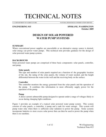
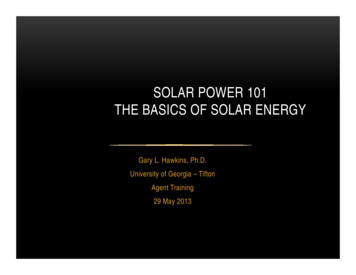
International Journal of Scientific & Engineering Research, Volume 7, Issue 4, April-2016ISSN 2229-5518659same frequency. Due to operating in the electromagnetic nearfield, the receiving devices must be no more than about aquarter wavelengths from the transmitter[9] .Unlike the farfield wireless power transmission systems based on travellingelectro-magnetic waves, Witricity employs near fieldinductive coupling through magnetic fields similar to thosefound in transformers except that the primary coil andsecondary winding are physically separated, and tuned toresonate to increase their magnetic coupling. These tunedmagnetic fields generated by the primary coil can be arrangedto interact vigorously with matched secondary windings indistant equipment but far more weakly with any surroundingobjects or materials such as radio signals or biological tissue.Fig 8.2 WorkingSTEP 3:- The energy of the oscillating magnetic fieldinduces an electrical current in the receiving coil, lighting thebulb [D].IJSERVIII. WORKING.STEP 1:- A circuit [A] attached to the wall socket convertsthe standard 60-hertz current to 10 megahertz and feeds it tothe transmitting coil [B]. The oscillating current inside thetransmitting coil causes the coil to emit a 10-megahertzmagnetic field.Fig 8.3 WorkingIX. BLOCK DIAGRAMFig 8.1 Working.STEP 2:- The receiving coil [C] has the exact samedimensions as the sending coil and thus resonates at the samefrequency and, in a process called magnetic induction, picksup the energy of the first coil's magnetic field.Fig 9.1 Block DiagramIJSER 2016http://www.ijser.org
International Journal of Scientific & Engineering Research, Volume 7, Issue 4, April-2016ISSN 2229-5518IX.1Working of TransmitterThe input from mains is given to the power and frequencycontroller.[10] The output of this system is given toMOSFET/IGBT. The main purpose of using MOSFET/ IGBTis to convert DC to AC and also for amplifying square waveat the gate input. The voltage given to the transmitting coilgenerates magnetic field around it. The capacitor is connectedto the coil parallel and hence the resonating circuit is formed.Until the resonant frequency of receiving coil matches withthe resonant frequency of the transmitting coil magnetic fieldwon’t get induced in the receiving coil. For this purpose ofmatching the resonant frequency we used different values of“L” and “C” for resonant frequency matching purpose. Tomatch the resonant frequency of the receiver and thetransmitter coil we used the switches to vary the time periodsof the square wave by which we are controlling the frequencyat output.IX.2Working of ReceiverAs the receiving coil comes in the range of the magnetic fieldof the transmitting coil, the voltage across the transmittingcoil gets induced in the receiving coil because of mutualinductance and matching of resonance frequency Thereceived voltage is in AC form, we have to convert it into DCfor DC load hence we used a rectifier circuit which providesconstant DC at the output for driving the load. And if the loadis ac load then we can give direct output to it.[11]660Where,L Inductance of Coil in HenrysN Number of turns in Coilμ Permeability of air (core material)A Area of coil in square metersl Average length of coil in metersEfficiency: During the transferring of energy there are someof the losses which takes place which reduces the efficiencyThere are hysteresis losses, eddy current losses ,attenuation,etc. which are responsible for the same.Less Range: As witricity is under the research sector, therange of wireless transferring of energy is still not upto themark.Solar efficiencySolar efficiency refers to the amount of light that can beconverted into usable electricity.Solar efficiency is dependent on 2 parametersSolar cell efficiency-Solar cell efficiency is the amount oflight that the individual solar cell coverts into electricity. It isthe ratio of the electrical output of the solar cell to theincident energy in the form of sunlight. This is calculated bydividing a cell's power output (in watts) at its maximumpower point (Pm) by input light (E, in W/m2) and the surfacearea of the solar cell (Ac in m2).IJSERȠ X. CALCULATIONThe transmitter is supplied with 18 volts AC and the currentcirculating in it will induce an electromotive force in thereceiving coil that will drive the light bulb. Theelectromagnetic wave is used to radiate energy with itsoscillating electric and magnetic fields. To make sure thefield stays strong, the two sides will be made to resonate atthe same magnetic frequency of 40 kHz. For calculating theresonant frequency we used the following formula:Where,F resonant frequency.L inductance value of coil.C capacitance value of coil.𝑃𝑚𝐸 𝐴𝑐Solar panel efficiency: - Solar panel efficiency is theamount of light that the entire module converts intoelectricity. The efficiency of solar panel is less than that ofsolar cell, due to the spacing which is present in between thecells and because of the glass covering over the panel whichreflects some of the sunlight.How to improve the efficiency of the solar panel:-Increasing the amount of electric current produced by thesolar panel can be done by augmenting its light surface withaluminum nanostructures. Another way to increase theelectric current produced by solar panel is by studying thelight receiving surface of Gallium Arsenide (GaAs) deviceswith aluminum nano cylinders. This magnified the scatteringof light in the visible part of the spectrum which dominatesthe energy in sunlight, the scattered light then travels alonger path so that more photons can be absorbed andconverted into current.X.1 Formula For Finding InductanceXI. CONCLUSIONN2 ϻAL lThe concept of wireless power transmission throughrenewable power generation is presented . Mainly focused onIJSER 2016http://www.ijser.org
International Journal of Scientific & Engineering Research, Volume 7, Issue 4, April-2016ISSN 2229-5518providing clean and efficient power transmission throughwireless medium, this would offer a major advancement inthe field of solar and wireless technology. Avoidance ofcables in power transfer reduces high cost affairs. Wirelesstechnology can be useful for providing power to autonomouselectrical and electronics devices .This energy which istransferred can be derived from a renewable source, here weuse solar energy. Solar energy is harnessed by means of solarcells. If the efficiency of transmitting power wirelessly isslightly increased , then wireless transmission become astandard means of charging any electronic gadgets. Alsosolar energy adds more efficiency to this scheme.REFERENCES[1] Nikola Tesla, My Inventions, Ben Johnston, Ed., Austin,HartBrothers, p. 91,1982[2] Nikola Tesla, “The Transmission of Electrical EnergyWithout Wires as a Means for Furthering Peace,” Electrical Worldand Engineer. Jan. 7, p. 21, wireless-power[4]transmissionIJSER[5] Wenzhen Fu, Bo Zhang, Dongyuan Qiu, "Study on Frequencytracking Wireless Power Transfer System by Resonant Coupling," PowerElectronics and Motion Control Conference, pp. 2658-2663, May 2009.[6] http://www.eecs.berkeley.edu/ hu/solar cells pages 0-40.pdf[7] https://en.wikipedia.org/wiki/Maximum power point tracking[8] https://en.wikipedia.org/wiki/Solar inverter[9] er-types-of-solarpanel-inverters/[10] B. Renil Randy, M.Hariharan, R. Arasa Kumar “Secured ”DOI:10.5121/ijist.2014.4315[11] Xiaolin Mou,” Wireless Power Transfer: Survey and RoadmapStudent Member”, IEEE and Hongjian Sun, Member, IEEE The researchleading to these results has received funding from the EuropeanCommission’s Horizon 2020 FrameworkProgramme (H2020/20142020) under grant agreement No. 646470, SmarterEMC2 Project,18feb 2011IJSER 2016http://www.ijser.org661
is done through wired medium. One of the major issue in power system is the losses occurs during the transmission and distribution of electrical power. As the demand increases day by . research dating back to the 1850's has led to the conclusion that WPT is possible. The three main systems used for WPT are microwaves, resonance, and solar .