Transcription
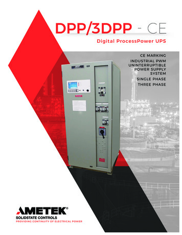
DPP/3DPP - CEDigital ProcessPower UPSCE MARKINGINDUSTRIAL PWMUNINTERRUPTIBLEPOWER SUPPLYSYSTEMSINGLE PHASETHREE PHASEPROVIDING CONTINUITY OF ELECTRICAL POWER
DPP/3DPPCE MARKINGIndustrial Pulse Width ModulatedUninterruptible Power Supply SystemDPP SINGLE PHASE 5-40 kVA3DPP THREE PHASE 10-80 kVAThe Digital ProcessPower(DPP) Uninterruptible PowerSupply (UPS) system fromAMETEK Solidstate Controls is atrue on-line, double conversionUPS system that providescontinuous, clean, regulated powerfor critical AC loads. Designedspecifically for process control andindustrial applications, the DPPsystems utilize state of the artPulse Width Modulation (PWM)technology. PWM incorporateshigh power IGBT semiconductorsand digital control for enhancedcommunications, monitoring,control and diagnosticscapabilities.Also essential to the DPP designis the use of fiber optic cablesfor control and communications;allowing for better isolation andfaster, more accurate signalsbetween processors. The DPPdesigns also include an LCDpanel and user-friendly touchscreen display for the ultimate inuser control. CE Marking (ConformitéEuropéenne) indicates thatthese UPS systems comply withthe essential requirements ofthe European health, safetyand environmental protectionlegislation The inclusion of the CE Markingalso ensures adherence to IEC60240 Parts 1, 2 & 3 T rue on-line, doubleconversion UPS P rovides continuous, clean,regulated power for criticalAC loads H igh power IGBT semiconductorsand digital control F iber optic cables used forcontrol and communications L CD panel and user-friendlytouch screen display D igital ProcessPower has loweraudible noise
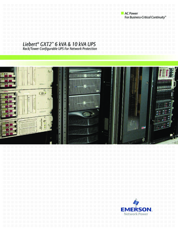
Enhanced Color DisplayOur user panel hardware and software have been redesigned, using proprietaryelectronics and the latest touchscreen technology available in the market.New benefits include: A larger, full color LCD display High-speed communication, via an enhanced USB connection Proprietary communication protocols provide accelerated communications withmultiple external systems Future-focused architecture allows for continued technology enhancements andimplementation Improved reliability via proprietary technology available only to AMETEKSolidestate ControlsPROCESSPOWERUPS SYSTEMLCD ANDTOUCH SCREENUSER PANELShown with optionalindicator lightsThe Power Behind the ProcessKeypad Controls and Switches Float/Equalize Initialization with Light Battery Test Initialization Inverter to Load with Light Bypass to Load with Light Static Switch Reset Retransfer Latching Alarm Reset Audible Alarm Silence Display On Inverter Enable (On/Off) Switch*Standard LED Indicators: UPS Normal and UPS TroubleStandard LCD Panel Indicators Equalize Time Remaining Charger Status (OK/Fail) Float/Equalize Status Inverter Status (OK/Fail) Synchronism Status (In/Out of Sync) S tatic Switch Position(Inverter or Bypass) M anual Bypass Position(Normal or Bypass) Bypass Status (OK/Fail)
DPP Specifications0.8 Load Power Factor at Rated kVA 120 VDC (60 Lead Acid Battery PP020-3DPP030-3DPP040-3Rated OutputPowerEfficiencyAC Input/Freq. AC Amps per Phase1Max DCCurrentAC Output Amps1kVAkWAC-DCDC-AC480/60208/60380/50@ 1.75 61Weight20.8 Load Power Factor at Rated kVA 240 VDC (120 Lead Acid Battery Cells)ModelNumberDPP030-3DPP040-3Rated OutputPowerkVA3040EfficiencykW2432AC-DC93%94%AC Input/Freq. AC Amps per ax DCCurrent@ 1.75 VPC128171AC Output 17,04621,3251.0 Load Power Factor at Rated kVA 120 VDC (60 Lead Acid Battery PP020-3DPP030-3Rated AC-DC92%92%92%92%93%93%AC Input/Freq. AC Amps per /6035477093139187380/502026395176102Max DCCurrent@ 1.75 VPC5582109164219328AC Output 24,1511.0 Load Power Factor at Rated kVA 240 VDC (120 Lead Acid Battery Cells)ModelNumberDPP030-3DPP040-3Rated OutputPowerkVA3040EfficiencykW3040AC-DC93%94%AC Input/Freq. AC Amps per Max DCCurrent@ 1.75 VPC161214AC Output 19,99226,657Model Coding“DD”“EE”“FF”“GG”AC Input Volts (code)DC Bus Volts (code)AC Output Volts (code)Freq (code)208 – (20)480 – (48)380 – (38)600 – (60)120 – (12)240 – (24)120 – (12)220 – (22)240 – (24)60 – (60)50 – (50)1Circuit Breakers are sized at a minimum of 125% of rated current.2Unit weights correspond to a 60 Hz unit. Contact us for 50 Hz unit weight.3 “HH”Output Power Factor(code)0.8 – (K)1.0 – (W) complete model number includes the AC input voltage, DC bus (link) voltage, AC output voltage, system frequency, output power factor, andAUPS configuration. To “build” a model number, use the “code” in the matrix shown above, following the example format: DPP010-DD-EE-FF-GGH-I-J; where DD AC Input Voltage; EE DC bus voltage; FF AC Output Voltage; GG System Frequency; H Output Power Factor (‘K’ for 0.8; ‘W’ for1.0); I 6(S) or 12(T) Pulse Charger design; J UPS configuration (‘F’ for Float, ‘P’ for Parallel Redundant).For Example: A 20 kVA with 480 VAC input; 120 VDC bus voltage; 120 VAC output; 60 Hz; 0.8 output power factor; 6 pulse charger; Float systemwould have the following model number: DPP020-48-12-12-60-K-S-F. For custom systems and for units which do not have a configurable modelnumber, insert a ‘C’ in the model number as follows: DPP020CSizes are subject to change. Top mounted cooling fans require 0.5 in (13 mm) additional height. Certain optional features and/or combinationsmay require larger cabinets.“I”“J”Charger Design (code)Config Code (code)6-Pulse – (S)12-Pulse – (T)Float – (F)Parallel (P)Cabinet Dimensions Inches MillimetersStyleGTD1XGTD2XHxWxD79 x 32 x 3679 x 54 x 36HxWxD2,007 x 813 x 9142,007 x 1,372 x 914
General Specifications – Optional FeaturesGeneral Specifications –Standard FeaturesMetering and System Measurements(Opt. #)Alarms (LCD)(Option #)AC Input Power (Voltage, Frequency, Current)(111)Charger Overload(119)System MeasurementsHigh DC Disconnect(2)(Displayed on LCD Panel)Bypass Input )Total Number of Battery DischargesBypass Input Voltage(113)High/Low Bypass Source Voltage(7/6)Total Operational Time on BatteriesOutput Power (kVA, kW, Power Factor)(114)High/Low AC Output Voltage(9/8)Average Time on Battery per Discharge% Inverter Loading(115)AC Power Failure(26)ACOutputOverload(40)Historical Min/Max Battery VoltageInverter Output cent Min/Max Battery VoltageCircuit Breaker(Opt. #)Out-of-Sync(43)Total Operation Time on UPS65 kAIC AC Input and Bypass Input(82/85)Inverter Fuse Blown(44)Total Operation Time on BypassInverter Output (Non-Automatic)(17)Inverter Off Frequency(45)Bypass Off Frequency(46)Total Operation Time on InverterAC Output (18)Battery Near Exhaustion(60)Metering (Displayed on LCD Panel)Battery High Interrupt Breaker(86)Low AC Input Voltage(68)DC VoltageMiscellaneous (Opt. #)High DC Voltage(5)DC Battery Current ( /-)Rectifier Configuration(34)MBS to Bypass(84)Charger Output Blocking Diode(29)AC Output VoltageAC Input CB Open(101)ChargerOutputRippleFilter(59)Bypass Input CB Open(103)AC Output CurrentLatching Alarms(28)AC Output CB Open(104)AC Output FrequencyLamp Test(35)High AC Input Voltage(124)Charger/Rectifier Output CurrentESI (Essential System Indicator) Panel(123)Communications(Option #)(132)Battery Voltage (with Rectifier Configuration) Alarm TestModbus RTU (RS485 Connection)(187)PrechargeCircuit(122)Circuit BreakersEthernet Webpage(187)Emergency Power Off(129)AC Input (14 kAIC, minimum)Modbus TCP(187)20% Spare Terminals(96)Consult Us for Additional Communications OptionsBattery Input (10 kAIC, minimum)Drip Shield(65)LED Indicators(Color)(Option #)Lifting Eye Bolts(105)Bypass Input (14 kAIC, minimum)Padlockable Circuit Breakers(93)In Sync(Green)(SNK)Alarms - All displayed on LCD Alarm PanelPCB Confrormal Coating(127)AC Input Available(Green)(14)with options for LEDs and RelaysFungusandMoistureProof(70)45Bypass Available(Green)(15)R Red LED A Amber LED Y Relay(Opt #)Parallel Redundant ConfigurationInverterAvailable(Green)(47)Fan FailureR, Y(120)12 Pulse Charger (10% Reflected Harmonics)ChargerAvailable(Green)(118)Charger FailureR, Y(69)14Remote External MBSAdditional LED Indicators (1 green, 9 red allowed)Low DC VoltageR, Y(11)5Additional Relay Contacts (Max of 13 allowed)Low DC DisconnectR, Y(107)Battery Breaker OpenR, Y(57)General Specifications – PerformanceBattery DischargingR, Y(BDC)Bypass Supplying Load A, YBattery Charger/RectifierStatic SwitchOver TemperatureR, Y(10)AC InputST/SW SCR FailureR, Y(SWF)Bypass Voltage 120, 220, 240 VACNominal Voltage2 208, 380, 415, 480, 600 VACBypass FailureR, Y(BPF)Inversely paired set of SCRs (one setInverter FailureR, Y(58)Switch TypeInput Range 10% (- 15% without discharging)per leg)IGBT DesaturationFrequency 50 or 60 Hz 5%Failure Mode Automatically fails to BypassOverload ShutdownRetransfer BlockedDC OutputTransfer Time Make Before BreakSystem Diagnostics –DC Bus Voltage(s) 110, 120, 220, 240 and 360 VDCSync Capture Range 0.5% to 1.5%Displayed on LCD Alarm PanelRegulation 1%1 Hz/sec to 10 Hz/secSlew RateLoss of System Communication(s)(adjustable)Ripple Voltage 2% with battery connectedPower Supply Failure(s)125% continuousSized to recharge a 30 minuteStandard RelaysThe following alarms also include one set ofnormally open and normally closed relaycontacts rated for 120 VAC at 8 amps(30 VDC at 8 amps; 125 V at 300 mil):UPS Trouble (Summary), BypassSupplying Load, UPS CommunicationsFailure (Summary)Applicable Standards,Codes and RegulationsCE MarkingNEMA PE-1ANSIANSI/NFPA 70IEEEUL/C-UL (UL1778)Unit Manufactured in ISO9001 Certified Facility150% for 10 minutes200% for 1 minute1,000% for 1 cycleManual Bypass Switch1Voltage 120, 220, 240 VACbattery to 95% of its rated capacityCapacity within 8 hours, while simultaneouslysupplying power to a fully loadedinverterFloat/Equalize 5% AdjustabilityOverload CapabilityInverterMounting Inside UPS/InverterDC InputNominal Voltage 110 V/55 (96-128 VDC)Range/ #of Cells 120 V/60 (105-140 VDC)(Lead Calcium Type) 220 V/110 (192-256 VDC)240 V/120 (210-280 VDC)EnclosurePositions Two600 VAC, rotary drum, make-beforeConstructionbreak typeTransfer Time Zero in both directions125% continuous150% for 10 minutesOverload Capacity200% for 1 minute1,000% for 1 cycleEnvironmentalAmbient Temperature 23 to 104oF (-5 to 40oC)Relative Humidity 0-95% non-condensingOperating Altitude 10,000 feet (3,048 meters)AC OutputInverter/UPS Ratings 5-40 kVAPower Factor 0.8 or 1.0AC Output Voltage2 120, 220, 240Regulation 1 %Voltage Adjustment 5 %Frequency 50 or 60 Hz; 0.1%Crest Factor 3:1Audible Noise3 65-72 dB(A) @ 4.9 feet (1.5 meter) typicalTotal Harmonic 100% linear load 3%Distortion (THD) 100% non-linear load 5%Transient Response 5% (0-100% load)Recovery Time 50 millisecond to 1%100% - continuousOverload Capacity 125% - 10 minutes150% - 1 minuteMechanicalCooling Aided Convection or ForcedAir, depending on kVA ratingand design (fans standardfor 40 kVA units and above)Cable Entry Top or Bottom Entry StandardCabinet Rating NEMA 1 / IP-20(IP-21 with addition optionaldrip shield)Mean Time Between 205,000 HoursFailure (MTBF)Internal Manual Bypass Switch is normally removed when aRemote Manual Bypass Switch is selectedCustom Input and Output Voltages available – Consult Us3Addition of drip shield may increase the noise by 1-3 dB(A)1 2
3DPP Specifications0.8 Load Power Factor at Rated kVA 120VDC (60 Lead Acid Battery Cells)Rated Output3PH AC Input/Freq ACEfficiencyModel NumberPowerAmps Per Phase1kVAkWAC-DC DC-AC 208/60 480/60 600/60 3%87%1375947753DPP040-3403293%87%181786399Max DCCurrent@ 1.75 VPC881311752633503PH AC Output AmpsPer 001,5001,9502,050kg499590680885930Heat Loss(BTU/hr)6,80710,21012,88019,32125,7610.8 Load Power Factor at Rated kVA 240VDC (120 Lead Acid Battery Cells)Rated Output3PH AC Input/Freq AC AmpsEfficiencyModel NumberPowerPer Phase1kVAkWAC-DC DC-AC 208/60 480/60 600/60 3Max DCCurrent@ 1.75 VPC1281712142573423PH AC Output AmpsPer 02,0502,1502,5503,400kg8859309751,1571,452Heat Loss(BTU/hr)17,04621,32526,65731,98842,6501.0 Load Power Factor at Rated kVA 120VDC (60 Lead Acid Battery Cells)Rated Output3PH AC Input/Freq AC AmpsEfficiencyModel NumberPowerPer Phase*kVAkWAC-DC DC-AC 208/60 480/60 600/60 93%87%181786399Max DCCurrent@ 1.75 VPC1101642193283PH AC Output AmpsPer tyleGTD1XGTD1XGTD2XGTD2XWeight2
Efficiency AC Input/Freq. AC Amps per Phase 1 Max DC Current AC Output Amps UPS Cabinet Style Weight2 Heat Loss (BTU/ kVA kW AC-DC DC-AC 480/60 208/60 380/50 @ 1.75 VPC 120 220 240 lb kg hr) DPP005-3 5 4 92% 87% 11 25 14 44 42 23 21 GTD1X 765 347 3,403 DPP007-3 7.5 6 92% 87% 16 37 20 66 63 34 31 GTD1X 930 422 5,105 DPP010-3 10 8 92% 87% 21 48 26 88 83 46 42 GTD1X 1,100