Transcription
U . S. Department of CommerceNational Bureau of StandardsResearch Paper RP1824Volume 39, September 1947Part of the Journal of Research of the National Bureau of StandardsValidity of the Cosine-Fourth-Power Law of IlluminationBy Irvine C. GardnerThe cosine-fourth-power law states that th e irra dia nce 1 a t a n y p oin t in the imageformed by a photographi c lens, in th e absence of vig nettin g , is equal t o Eo cos' {3, wh ere E ois the irra diance at the center o f the fi eld , and {3 is the a ngle between the axis of the lens andthe con juga te chief ray in th e object space. Althou g h not us ua ll y so st a ted , this law in volve sth e addition a l ass umpt ion th at the lens is free from dist ortion. \,yit h this a ss umpt ion ,t he la w applies rigorous ly when t he dia phragm is between th e lens a nd object a nd theobject is a t an infinite d ist a nce. If the diaphragm is betwee n t he lens a nd th e image plane,t here m ay be cases in which th e irra di a nce fa lls o ff les ra pid ly f rom t he center of the fi eldoutward than is p redicted by t he cos in e-fourth -po\\'er la w. A t ype of negat ive di st ort ionis d efin ed for wh ich the irrad ia nce is un ifo rm o ve r t he entire image. Wh en t he di aphragmis within t he lens syste m (t he m ore common co ndi t io n for pho tog raphic le nses) , o ne mus tk now t he dist ortion of the po rtion of the lens fo llo wing th e di aph rag m before a d efi nitest atem e nt regardin g the irrad ian ce of th e image ean be ma de. The departures fromexactness of the cos ine-fourth-powe r la w a rise p a rt ly beca use t he efl"ective a rea of theentrance pupil is a fun ction of t he obliquity of the inc ident chi ef ray. A m et hod is givenfor mcaRuri ng this vari a tion in effecti ve a rea.1. IntroductionThe cosine-four th-power law may be stated asfollows: In th e absence of vi gnet ting, th e irradiance (or the effective exposure) for differ ent partsof the image form ed by a photographic obj ectivevaries as the four th power of th e co inc of theangl e between Lhe axis and th e chief ray proceeding from the conjugate obj ec t area. Th e desirability of and the economic advantage r esul tingfrom the u 0 of photographic obj ective of extremely wid e angle has mad e it important to reinvestigate the validity of this law b ecause, unlessthe consequ ences of the cosine-fourth-power lawcan b e evaded , n egatives made with extremelywid e angle photographic obj ec tives will vary tosuch an extent in density from center to edge th a ttheir usef ulness is greatly r es tricted. Although thecosine-fourth-power law is commonly set forth asI T hroughou t the text or this papcr t he terms irradiance a nd radiance asd efi ned by t he Optical Socicty or America (J. Opt. Soc. Am . 3 , 184, 1944)will be uscd in stead or t he old er terms illumination a nd brightness . Illumi·nation and briglltness usually rela te to rad ia nt energy as evaluated in termsor the lumin osity ru net ion, a consid erat io n wh ich does n ot a ppl y wh endealing with a n imagc to be recorded by photograph y. All t he relationsinvolved in th is paper arc geometrical, and hence t he eq uations apply withequal rigor, whe t her a pplied t o radiant energy, radiation evaluated in t ermsor theluminosity runction, or radiatio n evaluated in terms or photograp hicsensitivi t y.Cosine-Fourth -Power Lawa precise s tatement of fac t, for most pho tographiclenses it is, at b est, an approxima te r ela tion.Slus areff 2 has publish ed a paper of fund am en talimportance in connection wi th thi subj ec t, inwhich h e demonstrates the importance of the ab errations of the pupils, a eh aracteristic that has b eenneglected in previous treatments of the cosinefOllJ"th-power law. H e concludes tha t th e irradiance of th e marginal parts of th e field can b e increased significantly b eyond that predicted by theco ine-fourth-power law by on e of the followingthree optical devices : appropriate ab errations ofthe entrance pupil ; the introd Llc tion of n ega tivedistortion; and the use of a strongly curved concave image field with a concave phoLographiC'plate. R eiss 3 has taken exception to some of them ethods of computation employed by Slussareffbut accepts the limited validity of the cosinefourth-power law and the importance of th e ab errations of the pupils. In the present di scussionthe derivations of Slussareff and R eiss will b ebrieHy r ep eated, and the treatment extend ed to·cases not previouslv consider ed.2J . Phys. USS R 4, 537 (1941) .Opt . Soc. Am . 35, 283 (1945) .3J.213
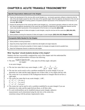
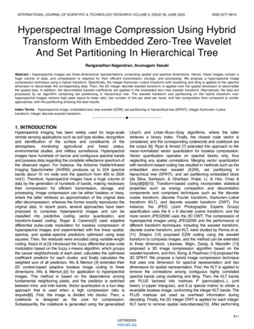
. --------II. Magnification Ratios and Distortion ofPupilssIf dF is the rad iant flux proceeding from oneelementary area, dA , to a second, dA' (see fig . 1),its magnitude is given by the equations, dAdA'dF B cos a cos a - -2r B COS adQ'dA BCOSs'e--- d A'(1 )dAa'dQdA'where B is the radiance of the radiating surface,r is the distance between the two elem entaryareas, a is th e angle between the radiu s VE'ctorand N , the normal to dA, and a' is the similarangle between the radius vector and N', thenormal to dA'. In the second and third equations,dQ' is the solid angle s ubtend ed by the area dA'at dA and dQ is the solid angle s ubtended bydA at dA'. The quantities dA and dA' entersymmetrically in these equations, and dF maybe assumed to represent th e flux proceeding ineither direction between the two elementaryareas, provid ed that th e appropriate value ofB is used. If the normals to the two elementaryareas are parallel, a a' and eq 1 becomesBdF 2 cos 4 adAdA',e(2)where e is t he distance between the parallel planescontaining dA and dA'.In figure 2 a photographic objective is represen ted with the conj ugate areas dA and dA' in thedA2. GeometTical variables governing the transfer ofradiant ene7'gy from the elementary area dA in the objectspace to the conjugate area dA' in the image space.FIGUREobj ect and image spaces resp ectively . At SandS', arc two additional planes normal to the axisof the lens, one b eing in the obj ect space and theother in the image space. The shaded pencil includes all rays proceedin g: -from dA through thelens to dA'. The cross sections of this pencil, inthe planes Sand S' are dS and dS', respectively.If, for the moment, absorption and reflectionlosses in the lens are neglect ed , B is the same foreach of the four elementary areas under consideration and the flux through all the cross sections ofthe pencil is the same. Therefore, applying eq 2,one may writeB4dAdS--- B,4'dA'dS' ,e2' cos {3e12 co" {3wh ere {3 is the angle between the elemen tary pencilin the object space and the normals to the parallelelements of surface dS and dA. In the imagespace, {3' is the corresponding a ngle. F rom eq 3dS' e'2 dA cos4 {3dS e dA' cos4 {3"dA'1. Geometrical variables that determine the fluxradiated from one elem entaTY aTea 10 a second.214(4)If it be assumed that the photographic lens is freefrom distor tion , dA/dA' l /}.;J2, where .LV! is themagnification. Equation 4 ca n, therefore, bewri ttenrFIGUR8(3)dS' / dS C cos 4 f3/ cos 4 {3',(5)where C e'2/e2}.;J2 is a constant independent of {3and {3'. It will now b e assumed that Sand S'arc th e planes of the entran ce and exit pupils, inwhi ch case dS and dS' are conjugate elementaryareas in the entran ce and exit pupils, r espectively.Journal of Research
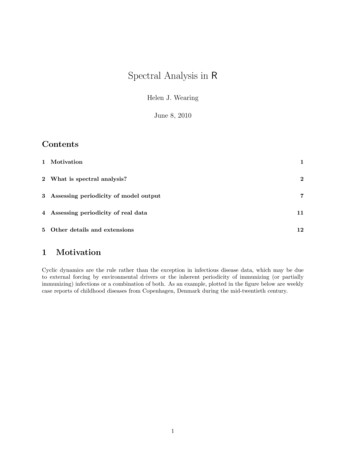
Eq uation 5 now h as a twofold interpretation. Ifit be assumed that the conjugate areas dA andciA' remain fixed , the ratio cos4 {3/cos 4 {3' will , ingeneral, b e different for differ ent pairs of conj ugateareas in the entrance and exit pupils. It followsthat the exit pupil will be a distorted image of theentrance pupil. If, on the other hand , dS andcIS' are assumed to be two conjugate elem entaryareas that con tain the axial points of the planesSand S', the rays making angles {3 and {3' withth e axis are chief rays. If now the positions ofdA and dA' are allowed to vary within the obj ectand image planes, the ratio cos 4 {3!cos 4 {3' will , ingeneral , not b e constant, and this indicates thatt he areal magnification at the axial point of th eexit pupil , with resp ect to the entrance p upil, is afunction of the inclination of the chief ray. Theseconclusions are in confli ct with dedu ctions basedon first-ord er imagery, and th e departures are ofthe same order as the variations of irradiance inthe image plan e w ith which we arc con cerned .Consequently, it is n ecessar y that th ese departuresfrom first order imagery no t b e n eglected whencomputing th e irradiance in differen t parts of thefield of a photographic objective.III. Irradiance at Any Point in ImagePlaneIf either m ember of eq. 3 is integrated overa rea of the correspond ing pupil, one obtainstotal flux through th e elementary area dA' inimage space. Dividing by dA', one obtainseq uationE e2BJ.VPfi!fcos 4 {3dS Be'2S'cos 4 {3'dS',theth etheth eIV. Special Illustrative Examples1. Diaphragm Follows the LensFor this example it is b ett er to integrate thethird m ember of eq 6 b ecause of the simpler limitsfor the integration. If the ap erture of the diaphragm is circular, of radius a, and if {3 is theangle between the axis and the chi ef ray passingthrough th e po in t under con ideration , the integralis seen to be id en tical with that .giving the irradian ce produ ced by a di sk of radius a and of uniformbrigh tness B at a poin t distant e' from the di skand at a di stance e' tan {3 from th e axis. Theexact valu e of this integral , as given by Foote 4may b e written in the formE 7r: [1 - (1 (x2: : a2)2)-!}(7)wh er e a is the diameter of the disk, k is th e di stan ceof the selected point from the plane of th e disk,and x is th e distance of th e point from th e axi .Th ese magnitudes a nd th eir eq uivalents in the(6)where E is the irradiancc. For a ny point in thefi eld of th e lens, for which vignetting does no tocc ur, either integration will give the correct valueof the irradiance. The angles {3 and {3' aredifferent for different po ints in the pupil areas Sand S', respectively, and arc also functions of th epoint in the field for which th e irradiance is b eingcomputed . Care must b e used in selecting theappropriate boundary for the area over which theintegration is extended . If the pupil over whiellone integrates is an actual physical diaphragm ,t h e integration is extend ed over th e aperture andthe limits of in t egration arc th e sam e for all pointsof th e field. On the oth er h a nd, if the pup il is animage of a diaphragm positioned som ewh ere elseCosine-Fourth-Power Lawin the optical system, eq 4 indicates that the areaover which th e integration is to b e performed , ingeneral , will be a function of the point in th e fieldfor which the irradiance is sought. The correctarea over which th e integration should extend isthe cross section of the complete pencil lying inthe pupil plane. Equ3,tion 6 will now be appliedto sp ecial cases that admit of general treatm ent.3. Geometrical quantities involved in computingI.he irmdiance produced by a disk of radius a and ofuniform mdiance at a distance e' }Torn the disk and at adistance e' tan {3' fl'om its axis.FIG UREpresent notation ar e shown in fig lire 3. If () isdefined as tan -la/k and {3 is defin ed as t:m - lx/k,eq 7 can b e written7rB [(4'tan 2 ())- J .E T 1- 1 4 cos {3o (1- tan2 () cos2 {3 )2(8) Bul. BS 12, 583 (J915) S263.215
With this notation the aperture ratio of the lensis 1 :N, where N 1/ (2 sin 8). For a point on theaxis, .B 0, and eq 8 reduces to th efamiliar equation(9)If cq 8 is expandcd wi t h reference to th e exponent - 1/2 b y th e binomial theorem and thefirst two term s of th e expansion retained , oneobtai ns th e eq uatiOtlBE'I --7r4' (tan 8cos {30 \ 1 - t ,an 2 8 cos 2 {3'0)2 (10)Equation 10 is not recommended for computational purposes, bu t it does show that the irradian ce produced by a uniformly irradiated disk ata point off the axis varies approximately as thefourth power of the cosin e of the angular displacement of the point from th e axis. B y thear gumcnt of th e preceding paragraph, it followsth at when a photographic objectivc h as the diaphragm between it and the image plan e, th e irradiance of the field vari es approximately as th e fourthpower of th e cosine of th e angle b etween the axisand th e ch ief ray in th e image space.An estimate of the degree of this approximationis afford ed by table 1.I. - Comparative val ues of iT radiance (or effectiveexposure) in the field of a photographic objective as afunction of relative ap ertuTe and angular distance f3 fromthe center of fie ld when the diaphragm is between the lensand the image planeT ABLEr-0020 30 40 Aperture ratio1.81:412---------- --------1.0001.000 cos' 20 1.002 cos' 30 1.004 cos' 40 1.0001.007 ros' 20 1.013 cos' 30 1.018 cos' 40 1.0001.027 cos' 20 1.0·)2 cos' 30 1.076 cos' 40 In this table, th e values of the irradiance havebeen compu ted by m eans of eq . 7, which is exact,for aperture ratios 1 :8, 1 :4, and 1:2 and for thevalues 0, 20, 30, and 40 d egrees. The computedvalues ar e expressed as th e product of cos4 {3 and anumerical coefficient. It will b e noted that thecoefficients of cos 4 .B are greater than 1 for pointsnot on the axis, indicating that the irradiance ofth e image falls off less rapidly than cos 4 .B . If alens is so d esign ed th at the second principal planelies between the lens and the focal plane, th e216diaphragm may b e placed in the second prinCIpalplane, and {3 will equal .B . In such a case, oneh as a lens in which th e irradiance of the im agedecreases from th e cen ter of th e field outward at arate somewhat less than that indicated by th ecosine-four th-power law, although th e departureis not of sufficient magni tude to b e of great importance photographically. It docs, however,sh ow conclu sively th at t h e cosine-fourth-powerlaw do es not r epresent a limi ting condition ofm aximum attainable uniformi ty of image irradiance. If the diaphragm precedes th e secondprincipal plane, {3 is greater than {3 , and th edeparture from th e cosin e-fourth-power law willbe still gr eater.2. Dia phragm Precedes the LensFor this example the first integral of eq 6 isth e one more conveni en t to apply. This integralrepresen ts t h e irradiance produced by a disk ofradius b, where b is th e radius of the entrance pupiland of brightness B/M2 at a distance e2 In mostcases encountered in practice, the obj ect will beat a distance of several focal lengths in fron t of th elens, and consequently th e numerical aperture ofthe incid ent pencil will be much less (N gr eater)than the values assumed in the preceding case .Referring to table I } it is evident that the irradiance will b e more n early proporti onal to th e fourthp ower of th e angle (m easured in the object space)th an for the preceding example. If, for example,the obj ect is 10 fo cal length s' distan t , th e apertureratio is approximately 1: ION. For a 1: 2 lells,the aperture ratio in t:te obj ect space, t herefore,becom es 1: 20, and it is clear that the departuresfrom th e cosine-fourth-power law will b e muchless th an those tabulated for the preceding example.3. Diaphragm Precedes the Lens, Object a tInfinite DistanceThis is a particular limiting case of the preceding example. When the first integral of eq 6 isapplied , it is discovered that e b ecomes infinite and1.1 ;[ becomes zero in the limit as th e di stan ce to th eobject increases. The limiting value of the productMe is r equired. If c denotes the distance fromthe first principal fo cus to the plane of the en tran cepupil,(11)M j / (e c)and(12)M e je/(e c).Journal of Res earch
It follows thatlim M e fe co(13)With the object at infinity, {3 is constant over theentrance pupil. From eq 6(14)and this example presents an instance in which thecosine-fourth-power law, as stated in th e introduction to thiE treatment, is precisely followed .4. Diaphragm in Plane of First Principal Focus,Object at Infinite DistanceThis is a particular case of example 3. Theimagery is telecentric in the image space, and allchief rays arc normal to the focal plane. As {3 equals zero for all parts of the image surface, ithas at times b een mi stakenly assumed that theirradiance will be uniform. It is evident thatthere is no thing in eq 6 to support this conclusion. The application of the first integral of eq 6gives the l'esult that has been obtained in thepreceding example and iJldicates the irradiancevaries as cos 4{3. If the second integral i applied,it mu st b e remembered that the exit pupil isinfinitely large and at an infinite distan ce. Thevalue of e' also become infinite and t he integralremains finite. Although it is true that {3 iszero for all th e pencils, test measuremen ts willindicate that th e solid angles included by thep encils at differ ent distances from th e center ofthe field are not equal but vary in accordance witheq 5, and consequ ently a correct evaluation oft he two integral of eq 6 gives identical resul ts.5 . Dia phragm Precedes Lens, Object at InfiniteDistance, Distortion PresentR eferring to the first in tegral of eq 6, when th ereis distortion the areal magnification, ]y[2 is afunction of {3 and must r emain wi thin the integral.If one writes(15)wher e .1ldg is th e areal magnification at the centerof the field, eq 6 becomes(16)and th e field is uniformly irradiated. I n thepresence of distortion, the linear magnification isCosine-Fourth- Power Lawnot the square root of the areal magnification. Fora system possessing rotational symmetry, it canbe shown that eq 15 is satisfied, providedr' Moe sin {3,(17)where r' is the radial distance from the center ofthe image plane to the image of an object pointdistant e tan {3 from the axis. Applying the condition that e b ecomes infinite, eq 16 becomesE BS/f,(18)where f is th e focal length corresponding to thescale of th e image in th e neighborhood of the axialpoint. Equation 17 can therefore be writtenr'-fsin {3.(19)For an undistorted image, th e correspondingequation isr" j tan {3.(2 0)Consequently, for an obj ect point at the ang ulardistance {3 from the axis, the linear distortion isf (sin (3-tan (3), which is negative and co rrespond sto " barrel shaped" disLortion. The ratio ofradial magnification of corresponding points in thedistor ted and undi tOtted images is dr' /dr" co 3{3.In general , when negative disto rtion is present,even thou gh it do es not follow eq 16 precisely, th eirracliance over t he fi eld is more nearl y lIniformthan when di sto rtion is absen t.6 . Diaphragm Between C omponents of Lens.M ost photographic objectives are des igned withth e diaphragm within th e optical system, and eq 6cannot b e applied in th e ge neral manner of thepreceding examples because neither the entrancenor exit pupil is a physical diaphragm, and theregion over which either integration must b e extended is a function of the position chosen in theimage field. It will be assumed that th e lens system is di vid ed into two parts, a and b of fo callengths f a and fb, th e subscrip t a r eferring to thepart of the lens b etween the object a nd diaphragm,and b to the part following the di aphragm. Equation 6 will be applied to th e part of t he lens consisting of the diaphragm and the part b. Theequation b ecomesE B/e2 I sa cos 4{3,t dSlld b(2 1)'217
wher e Set refers to the ar ea of the diaphragm, {3et isth e angle b etween a ray and th e lens axis in thespace occupied by th e diaphragm, and M b is th eareal magnification for th e part of the system under consideration. (It is assumed that the imageformed by t he first par t of th e system, whichserves as th e obj ect for th e sccond part, is stigmatic.) If th e rays passing through t he diapluagm and proceeding to any given point in th eimage fi eld are parallel, f3a is a cons tant over th ear ea of th e diaphragm , and eq 21 b ecomesE B/e2 cos4I Mbs 1f3dddS.(22)E ven if th e rays passing through the diaphragmare no t parallel, for most lens sy st ems in use, theinterm ediate image is r emote, and the aper tureratio of the beam is small. Consequently, as isshown by r efer ence to table 1, eq 22, while notrigorously exact, will b e a good approximation.The areal magnification lo.:fb will b e a constant ifpart b of the lens system introduces no distortion.In gen eral, however , par t b is a positive lens systempreceded by a diaphragm, and the distortion forsuch a sy stem is frequently n egative. As has been, mentioned , the effect of negative distortion is toincr ease t he irradiance of the peripher al part of theimage as compared with the central part. Formost photographic sys tems f3d is greater th an f3.Consequently, th e factor cos 4 f3et indicates a morerapid decr ease of irradiance from the center outward than would be predicted by the fac tor cos 4 f3 .Ther efore, in eq 22 , the factors 11M b and cos 4 f3etindica te departures from the cosine-fourth-powerlaw in opposite directions, and a system with aninternal diaphragm must b e carefully analyzedbefore it is possible to say in which direction theirradiance deviates from the cosine-fourth-powerlaw. In particular, if the portion of th e lens thatfollows t he diaphragm is free from distortion, M bis a constan t and, as is shown by eq 22, th e irradiance varies as t he fourth power of the angle bet ween the chief ray and the lens axis in th e spaceoccupied by th e diaphragm .V. Effect of Light Losses Introduced byconsiderably greater . Actually, the losses by r eflection and absorption for any elemen t of a len ssystem are functions of the angle at which thepencil of ligh t is inciden t. These losses, t her efore,are functions of {3 or {3' of eq 6, and if they are tob e correctly taken into account , the transmissioncoefficien t should be within t he integral sign.D eriving an analytical expression for th e loss byabsorption or reflection as a fun ction of the angleof inciden ce, involving th e curvatures of the several surfaces and th e variations in thickncss of th elens elemen ts introduces so many complica tions,however , that it is usual to consider the transmittance as independent of {3 or {3 ' and to write it infront of the integral sign , as a factor multipliedinto B. This gives r esults satisfactorily accuratefor most photometric qu estions that arise in conn ection with a photographic obj ective. When t het ransmission factor is written in front of the integral sign of eq 6, the magnitude of the factor doesno t affect the indicated variations in the irradianceof t he field that have been derived in the severalexamples of section IV. N eith er does the n eglectof th e effects of absorp tion and r eflection introduceany error in the geometric r elations that have beenderived between entrance and exit pupils.One can use a filter that is denser in the cen terand becomes more transparent from t he centeroutward. If such a filter is placed some distancefrom a pupil plane, t h e t ransmitted beams irradiating t h e cen tral parts of the field pass throughth e denser parts of th e filter while th e more obliqueb eams that irradiate the .p eripheral parts of th efi eld pass through th e outer less dense parts of th efil ter. Such a filter acts sel ectively to make th eirradiance of th e field more uniform. Unless onehas an abundance of light this is an undesirablem ethod for increasing the uniformity of irradianceb ecause it r educes the average irl'adiance andt herefore increases th e len gth of the requiredexposure. To compute the effect of such a fil ter ,the analy tical expression for i ts transmittance,as a function of {3 (or (3 ') should b e introduced intothe in tegrals of eq 6.Reflection or AbsorptionVI. Experimental Method for MeasuringPupilsIn the preceding examples it has been assumedt hat the len s is free from losses by r eflection andabsorp tion. In an uncoated len s system su chlosses are seldom less than 30 p ercent and may beWh n a pupil is the image of a diaphragm formedby a portion of the lens syst em , its size and shap ecan be most r eadily determined by a pho tographicmethod. If, for example, the size and shape of th e21 8Journa l of Res earch
entrance pupil are to be determined, a camera maybe placed in fron t of the l ens of which the pupilis to be measured and the diaphragm photographedthrough the parts of the lens that come b etweenthe actual physical dia,phragm and the objectspace. If the camera system is center ed on the axisof the lens and directed axially toward the diaphragm, one obtains the pupil corresponding to{3 O. If, now, the camera r emains fix ed and thelens under test is rotated through the angle (30about an axis in the plane of the entrance pupiland at the right angles to th e optical axis of thelens, one obtains the pupil corresponding to (3 (30'The images of the entrance pupils arc meas ured onthe resulting n egatives by means of a planimeterand multiplied by a suitable scale factor to determine the area of t he entrance pupil. The diaphragm aperture can b e irradiated to be pho tographed by a ground glass and lamp placed backof the lens. This m ethod of meas uremen t givesth e area of th e entra nce pupil as a ff ccted byvignetting if presen t. To similarly m eas ure theexit pupil, th e diaphragm is photographed througbthe back component of the lens und er test.The method of the preceding paragraph is satisfactory for most purposes but is not rigo rou slyaccurate b ecause, for th e oblique positions, different parts of th e pupil are at differ en t distancesfrom the lens and are reproduced to differentscales r esultin g in a distortion. This can beeliminated by using a telecentric systcm as shownin figure 4. The lens for which th e en trancepupil is to be determined i shown at A. Theentrance pupil, which is t he image of the d iaphragm formed by the first two elem en ts of th eHDiagrammatic sketch of arrangements of partsfor experimental determin:Ltion of the dimensions of anentrance pupil of a photographic objective.FIG URE 4.Cosine-Fourth-Power Lawsystem , is represented at B. Actually, for thecase illustrated, the entrance pupil would bewithin the lens, but it is shown h er e in front ofthe lens to emphasize its position in the obj ectspace. At C th ere is a lens, preferably correctedfor chromatic aberration, which has the sm alldiaphragm D in its second focal plane. L ens Gand image plane H schematically indicate thecam era with which the photograph is made. Thediaphragm at D should in r eality be the entrancepupil of the lens .G. In the obj ect space of lensC th e chief rays are parallel, and th erefore thedifferen t parts of the entrance pupil are r eprodu ced to th e same scale. This arrangementgives a correct determination of the entranr:epupil when the object is at an infinite distan ce.VII. Computational Method for Determining Diameters of PupilsTo determin e t he size of eith er en trance or exitpupil by compu tation is a tedious process. If theentrance pupil is to b e determined for the angle(30, a poin t in the obj ect plane distan t e tan (30 fromthe axis is chosen , a nJ rays from this point aretraced into th e lens as far as th e particular spacein which t he physical diaphrag m is locat-.od . Bys uccessive tests a series of rays ar e finally foundthat intersect th e edge of the diaphragm. Thetracing mllst be done trigonometrically a nd , skewrays are required. After a sufficient number ofrays intC'rsC'c tin g the edge of th e di aphragm havebeen traced, one can construct th e surface thatencloses all th e rays of the transmitted p encil.The cross section form ed by th e intersection ofthis surface with th e plan e of th e entrance pupild efines the entranc e pupil COITe ponding to (30'If there is vignetting, the rays must b e tracedthrough th e entire system and th e size of th emaximum transmitted b eam determ ined. Todetermine the exit pupil, one traces rays in asimilar manner, proceeding from the seleetedimage point in the r everse direction through thelens.WA SHI NGT ON,.M ay 7, 1947.219
The cosine-fourth-power law states that the irradiance 1 at any point in the image formed by a photographic lens, in the absence of vignetting, is equal to Eo cos' {3, where Eo is the irradiance at the center of the fi eld, and {3 is the angle between the axis of the lens and