Transcription
http://www.diva-portal.orgThis is the published version of a paper published in Applied Sciences: APPS.Citation for the original published paper (version of record):Paul, S., Morales-Menendez, R. (2019)Chatter Mitigation in Milling Process Using Discrete Time Sliding Mode Control withType 2-Fuzzy Logic SystemApplied Sciences: APPS, 9(20): 4380https://doi.org/10.3390/app9204380Access to the published version may require subscription.N.B. When citing this work, cite the original published paper.Permanent link to this version:http://urn.kb.se/resolve?urn urn:nbn:se:oru:diva-77448
appliedsciencesArticleChatter Mitigation in Milling Process Using DiscreteTime Sliding Mode Control with Type 2-FuzzyLogic SystemSatyam Paul 112*and Ruben Morales-Menendez 2, *School of Science and Technology, Örebro University, Örebro 70182, Sweden; satyam.paul@oru.seSchool of Engineering and Sciences, Tecnológico de Monterrey, Monterrey 64849, NL, MexicoCorrespondence: rmm@tec.mxReceived: 2 August 2019; Accepted: 11 October 2019; Published: 16 October 2019 Abstract: In order to achieve a high-quality machining process with superior productivity, it is veryimportant to tackle the phenomenon of chatter in an effective manner. The problems like tool wearand improper surface finish affect the milling process and are caused by self-induced vibrationtermed as chatter. A strategy to control chatter vibration actively in the milling process is presented.The mathematical modeling of the process is carried out initially. In this paper, an innovativetechnique of discrete time sliding mode control (DSMC) is blended with the type-2 fuzzy logic system.The proposed active controller results in a significantly high mitigation of vibration. The DSMCis linked to the time-varying gain which is an innovative approach to mitigate chattering. Thetheorem is laid down which validates that the system states are bounded in the case of DSMC-type-2fuzzy. Stability analysis is carried out using Lyapunov candidate. The nonlinearities linked with thecutting forces and damper friction are handled effectively by using the type-2 fuzzy logic system.The performance of the DSMC-type-2 fuzzy concept is compared with the discrete time PID (D-PID)and discrete time sliding mode control for validating the effectiveness of the controller. The betterperformance of DSMC-type-2 fuzzy over D-PID and DSMC-T1 fuzzy in the minimization of millingchatter are validated by a numerical analysis approach.Keywords: sliding mode control; vibration control; fuzzy logic1. IntroductionSelf-generated vibration in the machining process degrades the quality of the finished productand should be given due consideration as it is an important factor associated with manufacturingindustries [1]. The self-induced vibration termed as chatter is an important phenomenon which effectsthe machining process resulting in dimensional inaccuracy and minimization in the removal rate ofthe material (MRR). The chatter phenomenon also results in low quality finish with significant toolwear [2]. The chatter in the milling process generates a significant amount of vibration which incurs animproper finish due to the change in surface roughness resulting in less production and high deliverytime [3].Machining chatter can be mitigated by utilizing three different techniques. The first option isthe utilization of stability lobe diagram (SLD) where the parameters of the machine are choose fromoutside the stability lobes thus compensating the chattering phenomenon [4] . The second optionis to tweak the regenerative effect with the approach of machine parameter change in a continuousmanner. The main methodology associated with the second option is spindle speed variation (SSV) [5].The third option is the alteration of machine tool dynamics for expanding the chatter boundary byimplementing active or passive strategies. The most common type of passive devices used for vibrationAppl. Sci. 2019, 9, 4380; doi:10.3390/app9204380www.mdpi.com/journal/applsci
Appl. Sci. 2019, 9, 43802 of 20mitigation of the machining process are tuned mass damper (TMD) and dynamic vibration absorber(DVA) [6]. Yang et al. [7] have depicted an innovative concept for the mitigation of chatter in themilling process by making use of TMD. The main positive aspect of passive devices is it is very muchflexible with easy instillation, also it is of low cost and does not make the system unstable. However,the main constraint encountered by passive devices is the necessity to tune it accurately at particularfrequencies for superior vibration mitigation. So it is not always advantageous to use passive devicesdue to minimal robustness while handling changing machining conditions. The active control systemis a combination of suitable controllers, efficient sensors and dampers which, when implemented,improves the performance of machining with less vibration in the machine tool [8]. The technique ofactive damper control by implementing the methodology of direct feedback velocity is depicted in theworks of Ganguli et al. [9]. The innovative mechanism of active damper for the mitigation of chatterwhich is justified experimentally has been investigated by Harms et al. [10]. An effective mechanism isproposed in [11] involving an electrostrictive approach in combination with an active damper. Thecontrol law was established by using the technique of linear quadratic Gaussian (LQG) which provedto be efficient in terms of robustness and productivity. A concept involving a predictive model foractive control of chatter vibration with input constraints is suggested in the work of Zhang et al. [12].Chen et al. [13] developed an adaptive algorithm on the basis of Fourier series for active controlof chatter. Weremczuk et al. [14] proposed an algorithm to control milling chatter using an activeapproach and harmonic excitation methodology. Alharbi et al. [15] implemented the concept of PIDcontroller for chatter mitigation in the milling process.Cutting forces associated with the machining process involve nonlinearities [16]. The presenceof nonlinearities in a cutting force model is an important aspect and should be analyzedthoroughly [17–19]. Exhaustive research unveils that nonlinear modeling is an area of great interest andshould be given importance. Moradi et al. [20] demonstrated that the cutting forces are a combinationof square as well as cubic polynomial terms which are nonlinear in nature.In situations where the model of the milling procedure is unknown, fuzzy logic comes in veryhandy and effective. Fuzzy logic has earned great research reputation due to its capacity to dononlinear mapping thus maintaining robustness and simplicity. Liang et al. [21] proposed an innovativetechnique to control chatter in end milling by utilizing the concept of fuzzy logic system. Stabilityanalysis along with uncertainty compensation of the milling process was carried out efficiently bySims et al. [22]. An effective LMI approach was utilized for the development of static output feedbackcontroller for nonlinear systems described by a continuous-time T-S model [23]. An output PDC(OPDC) controller is proposed and the quadratic Lyapunov technique is implemented to extractthe asymptotic stability of the OPDC controller. A type-2 fuzzy logic system performs significantlybetter than type-1 fuzzy logic system due to its possession of additional DOF which is known asa footprint of uncertainty [24,25]. The concept and methodical approach associated with type-2fuzzy was demonstrated in the work of Liang and Mendel [26]. The most effective way to handleuncertainities is the implementation of type-2 fuzzy logic because it performs better than type-1 fuzzylogic [27]. Hassani et al. [28] utilized an immeasurable premise variable for detecting the faults inT-S fuzzy systems. In order to tackle the uncertainties in a suitable manner, interval type-2 fuzzy setswere introduced. Moreover, a comparison between robust unknown input fault detection observers(UIFDO) and an existent reference is carried out to validate that the interval type-2 T-S fuzzy model issuperior to type-1. In the work of Paul et al. [29], it is demonstrated that the type-2 fuzzy PD/PIDcontroller performed better than the classical fuzzy PD/PID controller in the control of vibration of thestructure. An innovative concept involving type-1 and type-2 fuzzy logic systems are proposed forpitch angle controlled wind energy systems as an application for the performance investigation. Theresults show that the type-2 fuzzy logic system offers better performance in comparison to type-1 fuzzylogic systems [30]. A comparison between type-1 fuzzy and type-2 fuzzy logic controllers implementedin laser tracking systems was carried out by Bai et al. [31]. The simulation results validated that thetype-2 fuzzy controller outperformed the type-1 fuzzy controller. The exhaustive research reveals that
Appl. Sci. 2019, 9, 43803 of 20type-2 fuzzy is superior to type-1 fuzzy. This fact initiate the research motivation of implementingtype-2 fuzzy controllers for chatter attenuation. The numerical analysis validated that the results wereimproved by the incorporation of a type-2 fuzzy logic system.Sliding mode control (SMC) is a superior control mechanism for vibration attenuation in millingtools since SMC exhibits the same movement pattern as that of the tool vibration pattern. SMCis most suited for nonlinear systems due to its specific design criteria [32]. An SMC controllerhandles the external noises and fluctuations associated with the parameters with greater effectiveness.Moradi et al. [33] investigated the chatter phenomenon in the turning process and proposed SMCfor chatter attenuation. A synergistic combination of proportional-integral (PI) control and fuzzysliding mode control (FSMC) was proposed by Zhao et al. [34]. In their work, fuzzy logic isutilized to compensate the nonlinearities whereas the PI control is implemented for chatter control.Ma et al. [35] developed an active sliding mode control strategy to mitigate the chatter in the turningprocess utilizing the concept of dynamic output feedback sliding surface combined with an adaptivelaw for noise approximation. A model based on an adaptive neuro-fuzzy inference system (ANFIS)and a novel fuzzy sliding mode controller (FSMC) was developed to control the vibration on vehiclethe suspension system [36]. An efficient controller based on adaptive hybrid control of interval type-2fuzzy controller in combination with a new modified sliding mode control is developed to control thevibration in magnetorheological mount [37]. Discrete time sliding mode control (DSMC) is an efficientcontroller for vibration attenuation due to its criteria of sampling period which is an important aspectin vibration control.Proportional-integral derivative (PID) control has been widely applied in industrialprocesses [38,39]. It is an important control strategy because it demonstrates superior capabilitieswithout the knowledge of the model and also due to its simplicity, as well as being incorporated withdistinct physical meanings. Alharbi et al. [? ] implemented the concept of PID controller for chattermitigation in the milling process. So in this paper, the PID controller is considered as a potentialcontroller for the comparison with the developed controller.This work is carried out by implementing the third option “active control of chatter”. In the firstinstance along x and y components, the mathematical modeling of the milling process is done. Then thenonlinearities are identified for efficient compensation. The actual outcomes of active vibration samper(AVD) was simulated using Matlab/Simulink for chatter suppression. The modeling is accomplishedby taking into consideration the dynamics of AVD. Discrete time sliding mode (DSMC) generatesthe control signals which are used for the suppression of chatter. DSMC is combined with type-2fuzzy logic (DSMC-T2 fuzzy) for efficiency. The implementation of the type-2 fuzzy system ensuresthat the nonlinearities are compensated in an effective manner. The approach of Lyapunov stabilityanalysis is implemented to prove that the DSMC-T2 fuzzy controller is a stable one. The chatterattenuation is achieved by the combined action of DSMC-T2 fuzzy with AVD. The wide significance ofthe concept and methodology is validated using numerical analysis. The results of the DSMC-T2 fuzzyare compared with discrete time sliding mode control with type-1 fuzzy (DSMC-T1 fuzzy) and discretetime PID (D-PID) to prove the effectiveness of the most suited controller. The numerical analysisresults validate that the methodology of chatter control can be implemented effectively in the real timemilling system. This can be achieved by designing and developing an AVD and placing it on the top ofthe milling spindle.2. Modeling of the Milling Process with Active ControlIn case of a milling tool with n evenly spaced teeth which is almost flexible to the rigid workpiece,a generalized 2-degrees of freedom mathematical model is [40,41]:Mm ẍc (t) Cm ẋc (t) Km xc (t) Fm (t)(1)the equivalent mass, damping and stiffness matrices are illustrated by the terms Mm , Cm andKm , respectively.
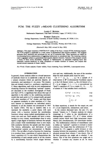
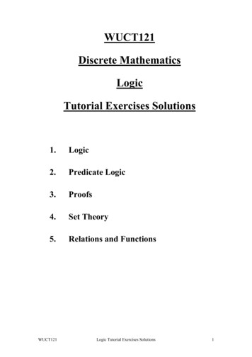
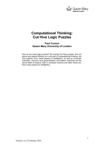
Appl. Sci. 2019, 9, 4380"Mm 4 of 20mmx00mmy#" 2 2, Cm cmx00cmy#" 2 2, Km k mx00k my# 2 2(2)Again, xc (t) [ x y] T illustrates the displacement of the tool along x and y components.Fm (t) [ Ff x Ff y ] T illustrates x and y component cutting forces. Along the x and y axes, the newform of Equation (1) is:"#"# "#"# "#"# "#Ff xmmx0ẍcmx0ẋk mx0x (3)0mmyÿ0cmyẏ0k myyFf ywhich generates:mmx ẍ cmx ẋ k mx x Ff xmmy ÿ cmy ẏ k my y Ff y(4)It is utter necessary to elaborate the dynamics of the cutting forces along the x and y components.Figure 1 illustrates the dynamics of the milling process [42,43]. The closed form equations representingthe nonlinear cutting forces along x and y components are illustrated as [20]:(ζ 1 x3 η1 y3 ζ 2 x2 η2 y2 ζ 3 x η3 y 3γ1 x2 y 3γ2 x y2 2γ3 x y γ4)(ζ 1 x3 η1 y3 ζ 2 x2 η2 y2 ζ 3 x η3 y 3γ1 x2 y 3γ2 x y2 2γ3 x y γ4 )NFx 2πFy N 2π(5)2πwhere x x (t τ ) x (t) and y y(t τ ) y(t). The time delay is illustrated as τ nΩ,Ω spindle speed (rad/s). If we consider the present and previous tool period instances, then it isrepresented by [ x (t) y(t)] and [ x (t τ ) y(t τ )] , respectively. Considering the start immersion angleas 0 and the exit angle as π2 , The calculation of the coefficients for half-immersion up-milling is: 1δ1 34 πξh 1 , ζ 2 i3 [ξ 2 2δ2 ] ,η2 31 [δ2 2ξ 2 ] , ζ 3 12 ξ 3 21 πδ3 ,hihihiη3 12 δ3 12 πξ 3 , γ1 14 δ1 41 πξ 1 , γ2 14 ξ 1 41 πδ1 ,ζ1 ζ 1 14 14 ξ 1 34 πδ1 , η1 η3 12 γ3 13 [δ2 ξ 2 ] , γ4 [ξ 4 δ4 ] δ1 34 πξ 1 , η1 41 ξ 1 34hπδ1 , ζ 2 , 13i[ δ2 2ξ 2 ] ,η2 h14(6) 2δ2 ] , ζ 3 12 δ3 12 πξ 3 ,hihi, γ1 14 ξ 1 41 πδ1 , γ2 14 δ1 41 πξ 1 ,13i[ ξ 2ξ 3 12 πδ3γ3 13where 0 is the start immersion angle andcutting force coefficients.[ξ 2 δ2 ] , γ4 [ δ4 ξ 4 ]π2is the exit angle. Moreover, ξ 1 , ξ 2 , ξ 3, ξ 4, δ1 , δ2 , δ3 , δ4 are theFigure 1. Illustration of milling process dynamics [42,43].
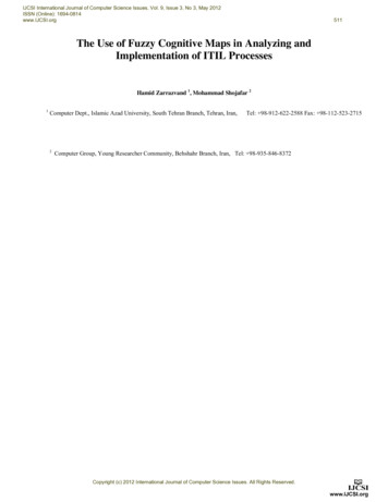
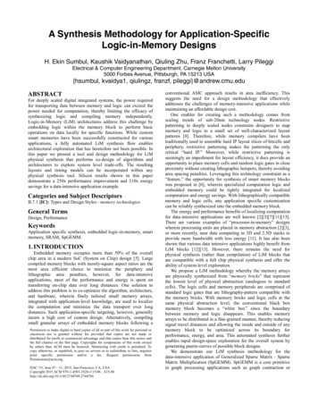
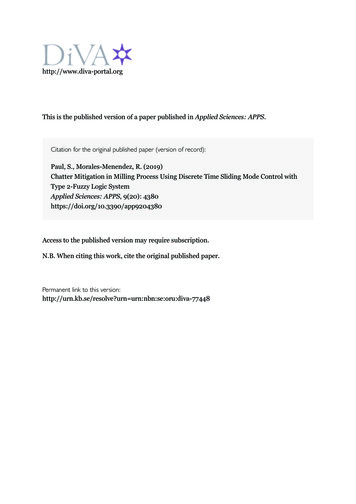
Appl. Sci. 2019, 9, 43805 of 20Active Vibration Damper (AVD) for Active Control MechanismAs seen from Figure 2, AVD is placed on the top of the spindle to minimize the tool chatteringgenerated by the external force. The main mechanism behind AVD is that it works as a linear servoactuator. A linear actuator converts the rotary motion of the motor to the required linear motion.The position of the AVD is at the center of mass (CM) and it makes an inclination ϕ with CM.It is considered to be an effective placement due to the mitigation of spacing problem of the AVD.The efficient placement of damper is cost effective, thus mitigating the requirement of two dampers.The combination of the modeling equation and control force uc yields:Mm ẍc (t) Cm ẋc (t) Km xc (t) Fm (t) uc dc(7) Tthe control signals impinged on the damper along both axes and is illustrated by uc ucx , ucy 2 1 ; dc dcx , dcy 2 1 is the combined damping-fricton effect resolved along two axes. Nowwith the control signals the closed loop Equation (1) can be illustrated as:mmx ẍ cmx ẋ k mx x Ff x ucx dcxmmy ÿ cmy ẏ k my y Ff y ucy dcy(8)f d md ( g̈i γ̈i )(9)The damper force f d is:where md mass of the damper, g̈i acceleration of the damper, γ̈i tool acceleration. Moreover,γ̈i2 ai,x ai,y implies the relative accelerations of the tool associated with both the axes. Now, f d canbe resolved along the x and y components as follows:fd γ̈i md ( g̈i cos ϕ ai,x )cos ϕai,yai,xcos ϕ sin ϕor f d md ( g̈i sin ϕ ai,y )sin ϕ(10)ẍi,x ai,x g̈i cos ϕ, ẍi,y ai,y g̈i sin ϕwhere ϕ, ẍi,x and ẍi,y represent the angle of the damper, relative acceleration of the damper along the xcomponent and the relative acceleration of the damper along y component, respectively. Now, f d isrepresented mathematically:fd mdmdsin ϕ g̈i ai,y(cos ϕ g̈i ai,x ) cos ϕsin ϕ(11) TThe control action along the x and y directions represented by uc ucx ucy is given by: Tuc mdi ẍi,x mdi ẍi,y(12)It is very important to consider the damper friction, which can be resolved as:dcx Λ ẋi,x Γmd g tanh [Υ ẋi,x ] dcy Λ ẋi,y Γmd g tanh Υ ẋi,y(13)where Λ, Υ and Γ are termed as damping coefficients associated with the Coulomb friction [44],Moreover, dc [dcx dcy ] T . Taking into consideration Equations (8) and (13), the combination of thecontrol methodology with the closed loop system is given by:mmx ẍ cmx ẋ k mx x Ff x ucx Λ ẋi,x Γmd g tanh [Υ ẋi,x ] mmy ÿ cmy ẏ k my y Ff y ucy Λ ẋi,y Γmd g tanh Υ ẋi,y(14)
Appl. Sci. 2019, 9, 43806 of 20 In Equation (14), the nonlinear terms are Λ ẋi,x Γmd g tanh [Υ ẋi,x ] , Λ ẋi,y Γmd g tanh Υ ẋi,y , Ff xand Ff y . The intelligent technique is incorporated to deal with the involved nonlinearities.Figure 2. AVD on Spindle Top.3. Discrete Time Sliding Mode Control with Type-2 Fuzzy CompensationGenerally the overall stiffness of machine tools is computed using the static loading test.The stiffness calculated by the static test, however, in general cases shows hysterics characteristics.This is due to the fact that the contact area of the bearing changes as the load direction changes [45,46].The stiffness has been modeled considering it to be a nonlinear in nature and is demonstrated effectivelyin [14]. The hysteric behavior can be handled effectively using the Bouc-Wen model. The behavior ofthe structure can be modeled using Bouc-Wen method which separates Equation (15) into two parts(elastic and inelastic) as [47]:f ρ,i eρi k ρi xρi (1 eρi )k ρi φρi(15)representing the positive numbers by ρ. The function illustrating nonlinearties (φρi ) is:φρi 1 haλ ẋηρi ρi ρi ρiηl 1iaρi vρi γρi ẋρi aρiηl 1ivρi aρi sign( ẋρi aρi )] κ ẋρii(16)In the above equation, the positive numbers are κ, λρi , γρi , αρi , n and η. Moreover, ηρi and vρirepresent the stiffness degradation control factor and strength degradation control factor, respectively.R t ẋρi aρiThe term, Eρi (1 αρi ) 0dt is defined as dissipated hysteretic energy in normal conditions. ρi ρi1 ηρiMoreover, (λ γ ). The stiffness f will be considered as nonlinear. The continuousρiρiρikntime model of the milling process, which is a closed loop system from Equation (14), is illustrated as:Mm ẍc (t) Cm ẋc (t) fkn (x) Fm (t) uc (t) dc(17)It is very important to discretize the milling process model for digitalization and to make itappropriate for the design of computer based control. For this, the following steps are implemented:V1 (t) xc and V2 (t) ẋc . The model represented by Equation (17) is illustrated as a state spacemodel by:Ż (t) AZ
Logic System Satyam Paul 1 and Ruben Morales-Menendez 2,* 1 School of Science and Technology, Örebro University, Örebro 70182, Sweden; satyam.paul@oru.se 2 School of Engineering and Sciences, Tecnológico de Monterrey, Monterrey 64849, NL, Mexico * Correspondence: rmm@tec.mx Received: 2