Transcription
Submitted toSouthern IndianaGas & Electric Companydba Vectren PowerSupply, Inc. (SIGECO)One Vectren SquareEvansville, IN 47708Submitted byAECOM9400 Amberglen BoulevardAustin, Texas 78729December 21, 2018CCR Certification:Initial Inflow Design Flood ControlSystem Plan§257.82for theSedimentation Pondat theA.B. Brown Generating StationRevision 0
AECOMCCR Certification: Initial Inflow Design Flood Control System Planfor the Sedimentation Pond at the A.B. Brown Generating StationiTable of ContentsTable of ContentsExecutive Summary .11Introduction . 1-11.1Purpose of This Report . 1-11.2Brief Description of Impoundment . 1-11.2.11.2.2234Inflow from Plant Operations and Stormwater Runoff . 1-2Outlet Structures . 1-2Hydrologic Analysis . 2-12.1Design Storm . 2-12.2Rainfall Data . 2-12.3Runoff Computations . 2-1Hydraulic Analyses . 3-13.1Process Flows . 3-13.2Storage Capacity . 3-13.3Discharge Analysis . 3-1Results . 4-14.1Inflow Analysis . 4-14.2Outflow Analysis . 4-24.3Inflow Design Flood . 4-24.4Discharge . 4-35Conclusions . 5-16Certification . 6-17Limitations . 7-1December 21, 2018
AECOMCCR Certification: Initial Inflow Design Flood Control System Planfor the Sedimentation Pond at the A.B. Brown Generating StationiiTable of ContentsTablesTable ES-1 – Certification SummaryTable 1-1 – CCR Rule Cross Reference TableTable 4-1 - Summary of Hydrologic and Hydraulic Analysis – 25-Year, 24-Hour StormTable 4-2 - Summary of Outlet Devices – 25-Year, 24-Hour StormAppendicesAppendix AFiguresFigure 1 – Location MapFigure 2 – Site MapFigure 3 – Drainage Area MapAppendix BHydrologic and Hydraulic CalculationsDecember 21, 2018
AECOMCCR Certification: Initial Inflow Design Flood Control System Planfor the Sedimentation Pond at the A.B. Brown Generating StationES-1Executive SummaryExecutive SummaryThis Coal Combustion Residuals (CCR) Initial Inflow Design Flood Control System Plan (Inflow Flood ControlPlan) for the Sedimentation Pond at the Southern Indiana Gas & Electric Company, dba Vectren Power Supply,Inc., A.B. Brown Generating Station has been prepared in accordance with the requirements specified in theUSEPA CCR Rule under 40 Code of Federal Regulations §257.82 (a).This Inflow Flood Control Plan meets all requirements as summarized in Table ES-1.Table ES-1 – Certification SummaryReportSectionCCR Rule ReferenceRequirement SummaryRequirementMet?CommentsInitial Inflow Design Flood Control System Plan4.1§257.82 (a)(1)Adequately manage flow intothe CCR unit during andfollowing the peak discharge ofthe inflow design floodYesCCR unit has the storagecapacity to handle theinflow design flood4.2§257.82 (a)(2)Adequately manage flow fromthe CCR unit to collect andcontrol the peak dischargeresulting from the inflow designfloodYesThe outlet devices of theCCR unit control the peakdischarge from the inflowdesign flood4.3§257.82 (a)(3)Required Inflow design flood forIncised ImpoundmentYesInflow design flood utilizedwas the 25 year event4.4§257.82 (b)Discharge handled inaccordance with §257.3 – 3YesCCR unit discharges inaccordance with theexisting NPDES permitThe Sedimentation Pond is an incised impoundment, hence a hazard potential classification was not performed.Hence, per §257.82 (a)(3), the inflow design flood is the 25-year flood for an incised impoundment. In accordancewith the requirements of §257.82 (a)(3), an Inflow Flood Control Plan was developed for the Sedimentation Pond.This was accomplished by evaluating the effects of a 24-hour duration design storm for the 25-year Inflow DesignFlood (IDF) to evaluate the Sedimentation Pond’s ability to collect and control the 25-year IDF of 5.65 inches,under existing operational and maintenance procedures.December 21, 2018
AECOMCCR Certification: Initial Inflow Design Flood Control System Planfor the Sedimentation Pond at the A.B. Brown Generating StationES-2Executive SummaryThe results for the Sedimentation Pond indicate that the CCR unit has sufficient storage capacity and outletdevices to adequately manage inflows and collect and control outflows during peak discharge conditions createdby the 25-year IDF.December 21, 2018
AECOMCCR Certification: Initial Inflow Design Flood Control System Planfor the Sedimentation Pond at the A.B. Brown Generating Station1-1Introduction1 Introduction1.1Purpose of This ReportThe purpose of the Initial Inflow Design Flood Control System Plan (Inflow Flood Control Plan) is to document thatthe requirements specified in 40 Code of Federal Regulations (CFR) §257.82 have been met to support thecertification required under each of the applicable regulatory provisions for the A.B. Brown Generating StationSedimentation Pond. The Sedimentation Pond is an existing coal combustion residuals (CCR) surfaceimpoundment as defined by 40 CFR §257.53.The A.B. Brown Station has a Type III Restricted Waste Site (RWS) Landfill facility that is utilized for the disposalof Flue Gas Desulfurization (FGD) residuals. The Sedimentation Pond currently collects and stores runoff solelyfrom this Landfill facility. The following table summarizes the documentation required within the CCR Rule and thesections that specifically respond to those requirements of this plan.Table 1-1 – CCR Rule Cross Reference TableReport SectionTitleCCR Rule Reference4.1Inflow Analysis§257.82 (a)(1)4.2Outflow Analysis§257.82 (a)(2)4.3Inflow Design Flood§257.82 (a)(3)4.4Discharge handled in accordance with §257.3 – 3§257.82 (b)Analyses completed for the hydrologic and hydraulic assessments of the Sedimentation Pond are described inthis report. Data and analyses results in the following sections are based on spillway design information shown ondesign drawings, topographic surveys, information about operational and maintenance procedures provided bySouthern Indiana Gas & Electric Company, dba Vectren Power Supply, Inc. (SIGECO), and limited fieldmeasurements collected by AECOM. The analysis approach and results of the hydrologic and hydraulic analysespresented in the following sections were used by AECOM to confirm that the Sedimentation Pond meets thehydrologic and hydraulic capacity requirements of the rules referenced above for CCR surface impoundments.1.2Brief Description of ImpoundmentThe A.B. Brown Station is a coal-fired power plant located approximately 10 miles east of Mount Vernon in PoseyCounty, Indiana and is owned and operated by SIGECO. The station is situated just west of the VanderburghPosey County line and north of the Ohio River with the Sedimentation Pond positioned on the north side of thegenerating station.December 21, 2018
AECOMCCR Certification: Initial Inflow Design Flood Control System Planfor the Sedimentation Pond at the A.B. Brown Generating Station1-2IntroductionThe A.B. Brown Station operates a Type III Restricted Waste Site CCR landfill, and stormwater from the landfill ismanaged via a perimeter ditch system. One of the reaches of the perimeter ditch system collects and conveyscontact flow from the southern end of the landfill in a clockwise direction to the lined Sedimentation Pond. TheSedimentation Pond, constructed in 2015, is approximately 1.3 acres in size, and manages and treats contactstormwater produced from the active cell portions of the landfill. The liner system for the Landfill SedimentationPond consists of an 80 mil geomembrane covered with a 16 ounce non-woven geotextile, underlining a geogridand 6 inches of #9 crushed stone over the entire geogrid. The pond liner is overlain with a layer of 6 inch D50 riprap. Supernatant from the Landfill Sedimentation Pond is conveyed to the Capital Pond via an overflow pipe.1.2.1Inflow from Plant Operations and Stormwater RunoffThe Sedimentation Pond will be operational through the life of the Type III Restricted Waste Site CCR landfill. Theprimary purpose of the Sedimentation Pond is to collect contact stormwater runoff from the landfill. TheSedimentation Pond discharges to a collection manhole via an 18” HDPE pipe during normal operatingconditions. No process water discharge from the A.B. Brown Station is conveyed to the Sedimentation Pond. TheSedimentation Pond also receives water that drains from the waste in the landfill.Upstream areas that contribute runoff are captured by the Stormwater Runoff Pond to the north. Approximately41.6 acres of the active landfill area drain to the Sedimentation Pond.1.2.2Outlet StructuresThe Sedimentation Pond has two outlet devices, one acting as the primary outlet device and the other acting as asecondary outlet device. The primary outlet device is located on the northern embankment of the SedimentationPond. It is a 24-inch diameter HDPE riser pipe inlet with staggered slots and has an overflow invert elevation of400.0 feet. The riser inlet connects to an 18-inch diameter HDPE pipe at an invert elevation of 397.50 feet thatdischarges into the collection manhole. The slots on the riser are located at a spacing of 1-foot center to centeralong the riser’s length. The secondary outlet device is a flat bottom broad crested rectangular weir that is 20 feetwide and has an invert elevation of 404.0 feet. The total length of the weir is approximately 850 feet.December 21, 2018
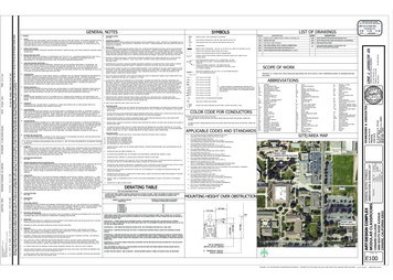
AECOMCCR Certification: Initial Inflow Design Flood Control System Planfor the Sedimentation Pond at the A.B. Brown Generating Station2-1Hydrologic Analysis2 Hydrologic Analysis2.1Design StormThe Sedimentation Pond is an incised impoundment; hence a hazard potential classification was not performed.Hence, per §257.82 (a)(3), the inflow design flood is the 25-year flood for an incised impoundment. In accordancewith the requirements of §257.82 (a)(3), an Inflow Flood Control Plan was developed for the Sedimentation Pondwhich indicates that the inflow design flood is the 25-year return frequency design storm event.2.2Rainfall DataThe rainfall information used in the analysis was based on the National Oceanic and Atmospheric Administration(NOAA) Atlas 14, Volume 2, Version 3 which provides rainfall data for storm events with average recurrenceintervals ranging from 1 to 1,000 years and durations ranging from 5 minutes to 60 days. The design stormrainfall depth, obtained from the NOAA website, is 5.65 inches for the 25-year, 24-hour storm. The Indiana HuffThird Quartile rainfall distribution used by AECOM is appropriate to use for storms up to the 1,000-year, 24-hourflood at the project site.2.3Runoff ComputationsThe drainage areas for the Sedimentation Pond were determined using a computer-aided design (CAD) analysisof topographic surveys completed in 2018. Approximately 41.6 acres of the active landfill area drain to theSedimentation Pond. In addition to rain that falls directly into the pond, there are no upstream areas thatcontribute runoff to the impoundment. See Figure 3 in Appendix A for the Drainage Area Maps.Runoff was calculated using the SCS Curve Number Method, where curve numbers (CN) were assigned to eachsubcatchment based on the type of land cover and soil type present. Using the USDA Natural ResourcesConservation Service (NRCS) Web Soil Survey, the soil type of the site was determined to be a mixture of soiltypes AIE, AIC3, UnB2 and Ud. The hydrologic soil group associated with each soil type was used. The soilsurvey listed soils AIE and AIC3 as Hydrologic Soil Group B and UnB2 and Ud as Hydrologic Soil Group C. CNvalues for the land cover were selected from the CN Table available in HydroCAD. This data was obtained fromthe SCS NRCS Technical Release-55 (TR-55) publication. Areas that were classified as Hydrologic Soil Group Chad 50-75% Grass Cove and determined to have a CN value of 79. Areas that were classified as Hydrologic SoilGroup B had 50% Grass Cover and 50%-75% Grass Cover and their CN values were determined to be 79, and69 respectively. The water surface was determined to have a CN value of 98.The time of concentration is commonly defined as the time required for runoff to travel from the mosthydrologically distant point to the point of collection. Calculations for the time of concentration for each subwatershed were performed in HydroCAD and are included in Appendix B.Stormwater runoff from the 25-year rain event into the Sedimentation Pond has an inflow of 15.30 cfs and inflowvolume of 10.94 acre-feet. Refer to Appendix B for HydroCAD results.December 21, 2018
AECOMCCR Certification: Initial Inflow Design Flood Control System Planfor the Sedimentation Pond at the A.B. Brown Generating Station3-1Hydraulic Analysis3 Hydraulic Analyses3.1Process FlowsThe Sedimentation Pond impoundment’s primary purpose is to collect and store runoff and water that drains fromthe waste areas from the Type III Restricted Waste Landfill facility. No additional flows from the surrounding areaor the A.B. Brown Station process flows enter the Sedimentation Pond.3.2Storage CapacityThe storage volumes for the Sedimentation Pond were determined using a computer-aided design (CAD) analysisof topographic surveys completed in 2018. The volume of storage was calculated by estimating the incrementalstorage area present for multiple elevations within the updated topographic surface supplied by SIGECOrepresentatives. The incremental storage area was input as a prismatic storage to develop incremental storagevolumes which was then used to calculate a cumulative storage volume in HydroCAD. The volume of storagewithin the Sedimentation Pond from normal pool elevation of 397.50 feet to the top of embankment elevation of404.0 feet is 5.53 acre-feet. Although the water surface elevation normally operates at an elevation of 397.50 feet,the water surface level can fluctuate. For the purpose of this hydraulic analysis, the water surface elevation wasassumed to be steadily maintained at an operating level of 397.50. Refer to Appendix B for further storagevolume details.3.3Discharge AnalysisA hydraulic model was created in HydroCAD 10.00 to assess the capacity of the pond to store and convey thestorm flows. HydroCAD has the capability to evaluate each pool within the network, to respond to variabletailwater, pumping rates, permit flow loops, and reversing flows. HydroCAD routing calculations reevaluate thepond’s discharge capability at each time increment, making the program an efficient and dynamic tool for thisevaluation.The analyzed scenario assumes a starting water surface elevation of 397.50 feet with its uppermost embankmentat 404.0 feet. The peak elevation caused by the 25-year rain event is 401.04 feet. Therefore, the facility does notcause a discharge of pollutants into waters of the United States and is in compliance with the requirements of theNPDES under section 402 of the Clean Water Act.December 21, 2018
AECOMCCR Certification: Initial Inflow Design Flood Control System Planfor the Sedimentation Pond at the A.B. Brown Generating Station4-1Results4 ResultsThe hydrologic and hydraulic conditions of the Sedimentation Pond were modeled with the peak discharge of the25-year storm event.Regulatory Citation: 40 CFR §257.82 (a);-The owner or operator of an existing or new CCR surface impoundment or any lateral expansion of aCCR of a CCR surface impoundment must design, construct, operate, and maintain an inflow designflood control system as specified in paragraphs (a)(1) and (2) of this section.4.1 Inflow AnalysisRegulatory Citation: 40 CFR §257.82 (a); (1) The inflow design flood control system must adequately manage flow into the CCR unit during andfollowing the peak discharge of the inflows design flood specified in paragraph (3).Background and AssessmentRunoff to the impoundment from the active landfill area is the total inflow to the Sedimentation Pond. Using theHydroCAD model, the total inflow was stored and routed through the outlet devices of the Sedimentation Pond todetermine the peak water surface elevations.Table 4-1 summarizes the water surface elevations of the Sedimentation Pond prior to and after the inflow designflood.Table 4-1 - Summary of Hydrologic and Hydraulic Analysis25-Year, 24-Hour StormCCR UnitBeginning WSE(feet)Sedimentation Pond397.501Peak WSE(feet)Top of EmbankmentElevation (feet)401.04404.0Freeboard AbovePeak WSE(feet)2.96Notes:1WSE Water Surface Elevation used for hydraulic analysisConclusion and RecommendationNo modifications are necessary or recommended to this unit for compliance with the CCR Rule.As there is adequate storage within the Sedimentation Pond to manage the inflow design flood as well as thecontact water from the landfill, there is no anticipated overtopping of the Sedimentation Pond embankment, whichmeets the requirements in §257.82 (a)(1).December 21, 2018
AECOMCCR Certification: Initial Inflow Design Flood Control System Planfor the Sedimentation Pond at the A.B. Brown Generating Station4-2Results4.2 Outflow AnalysisRegulatory Citation: 40 CFR §257.82 (a); (2) The inflow design flood control system must adequately manage flow from the CCR unit to collect andcontrol the peak discharge resulting from the inflow design flood specified in paragraph (3) of this section.Background and AssessmentRunoff to the impoundment arises from the Type III Restricted Waste Site Landfill facility to produce the totalinflow to the Sedimentation Pond. Using the HydroCAD model, the total inflow was stored and routed through theoutlet devices of the Sedimentation Pond to determine the peak flowrate and velocity through the outlet devices.Table 4-2 summarizes the peak flowrates and velocities through each of the outlet devices.Table 4-2 - Summary of Outlet Devices25-Year, 24-Hour StormInvert ElevationPeak FlowrateVelocity at PeakFlowrateOutlet DeviceType and Size(feet)(cfs)(fps)Riser Pipe18” HDPE397.5013.557.67Top of Embankment20’ wide crestedrectangular weir404.0--Conclusion and RecommendationNo modifications are necessary or recommended to this unit for compliance with the CCR Rule.As the Sedimentation Pond outlet devices manage the discharge of the inflow design flood and the runoff andwaste drainage flows from the Type III Restricted Waste Site Landfill without the peak water surface elevationovertopping the Sedimentation Pond embankment, the pond meets the requirements in §257.82 (a)(2).4.3 Inflow Design FloodRegulatory Citation: 40 CFR §257.82 (a); (3) The inflow design flood is:-(i) For a high hazard potential CCR surface impoundment, as determined under §257.73(a)(2), theprobable maximum flood;-(ii) For a significant hazard potential CCR surface impoundment, as determined under §257.73(a)(2), the1,000-year flood;-(iii) For a low hazard potential CCR surface impoundment, as determined under §257.73(a)(2), the 100year flood; or-(iv) For an incised CCR surface impoundment, the 25-year flood.December 21, 2018
AECOMCCR Certification: Initial Inflow Design Flood Control System Planfor the Sedimentation Pond at the A.B. Brown Generating Station4-3ResultsBackground and AssessmentThe calculations for the inflow design flood are based on the hazard potential given to the impoundment. Thedifferent classifications of the impoundment hazard potential are high, significant, and low. A hazard potentialclassification is not required if the impoundment is incised.Conclusion and RecommendationAs the impoundment was incised, the 25-year design storm was utilized in the analysis, which meets therequirements in §257.82 (a)(3).4.4 DischargeRegulatory Citation: 40 CFR §257.82 (b);- Discharge from the CCR unit must be handled in accordance with the surface water requirements under:§257.3 – 3.Background and AssessmentThe discharge for the Sedimentation Pond goes to the Collection Manhole which eventually drains to the CapitalPond to the north. Since the Sedimentation Pond doesn’t drain directly to a permitted NPDES outfall and does notrelease environmental contaminants to the waters of the United States it meets the requirements under section402 of the Clean Water Act to meet the CCR rule.Conclusion and RecommendationNo modifications are necessary or recommended to this unit for compliance with the CCR Rule.December 21, 2018
AECOMCCR Certification: Initial Inflow Design Flood Control System Planfor the Sedimentation Pond at the A.B. Brown Generating Station5-1Results5 ConclusionsThe Inflow Flood Control Plan of the Sedimentation Pond adequately manages flow into the CCR unit during andfollowing the peak discharge of the 25-year frequency storm event inflow design flood. The inflow design floodcontrol system of the Sedimentation Pond adequately manages flow from the CCR unit to collect and control thepeak discharge resulting from the 25-year frequency storm event inflow design flood. Therefore, theSedimentation Pond meets the requirements for certification.The contents of this report, specifically Section 1 through Section 4, represent the Initial Inflow Design FloodControl System Plan for this site.December 21, 2018
AECOMCCR Certification: Initial Inflow Design Flood Control System Planfor the Sedimentation Pond at the A.B. Brown Generating Station7-1Limitations7 LimitationsBackground information, design basis, and other data have been furnished to AECOM by SIGECO, whichAECOM has used in preparing this report. AECOM has relied on this information as furnished, and is notresponsible for the accuracy of this information. Our recommendations are based on available information fromprevious and current investigations. These recommendations may be updated as future investigations areperformed.The conclusions presented in this report are intended only for the purpose, site location, and project indicated.The recommendations presented in this report should not be used for other projects or purposes. Conclusions orrecommendations made from these data by others are their responsibility. The conclusions and recommendationsare based on AECOM’s understanding of current plant operations, maintenance, stormwater handling, and wastehandling procedures at the station, as provided by SIGECO. Changes in any of these operations or proceduresmay invalidate the findings in this report until AECOM has had the opportunity to review the findings, and revisethe report if necessary.This hydrologic and hydraulic analysis was performed in accordance with the standard of care commonly used asstate-of-practice in our profession. Specifically, our services have been performed in accordance with acceptedprinciples and practices of the geological and geotechnical engineering profession. The conclusions presented inthis report are professional opinions based on the indicated project criteria and data available at the time thisreport was prepared. Our services were provided in a manner consistent with the level of care and skill ordinarilyexercised by other professional consultants under similar circumstances. No other representation is intended.While the CCR unit adequately manages the inflow design flood, SIGECO must perform routine maintenance onthe CCR unit to continually manage flood events without failure. Outlet devices should be cleared of debris thatcould block or damage the device. Pipes and intake structures should be monitored and repaired if deteriorationor deformation occurs. All grass lined slopes should be examined for erosion and repaired if damaged. Rip-raplined channels should be inspected for stones that have shifted or bare spots that have formed. Replace rip-rapas needed.December 21, 2018
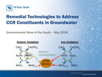
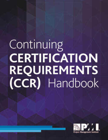
AECOMCCR Certification: Initial Inflow Design Flood Control System Planfor the Sedimentation Pond at the A.B. Brown Generating StationAppendix AFiguresFigure 1 – Location MapFigure 2 – Site MapFigure 3 – Drainage Area MapDecember 21, 2018
9400 Amberglen BoulevardAustin, TX 78729-1100512-454-4797 (phone)512-454-8807 (fax)SOUTHERN INDIANAGAS AND ELECTRICCOMPANYdba VECTREN POWERSUPPLY, INC.One Vectren SquareEvansville, IN 477081-800-227-1376 (phone)A.B. BROWNGENERATING STATIONMT. VERNON, INTYPE III RWS LANDFILL(FGD LANDFILL)IDF CERTIFICATIONSEDIMENTATION PONDSEDIMENTATION PONDISSUED FORCERTIFICATIONUPPER ASH POOLISSUED FOR BIDDINGISSUED FOR CONSTRUCTIONA.B. BROWNGENERATING R ASH POOL60442676AECOM PROJECT NO:DRAWN BY:AGDESIGNED BY:AGJMMCHECKED BY:DATE CREATED:PLOT DATE:12/15/2018AS SHOWNSCALE:ACAD VER:2014SHEET TITLELOCATION MAP010002000SCALE IN FEET3000FIGURE 1
9400 Amberglen BoulevardAustin, TX 78729-1100512-454-4797 (phone)512-454-8807 (fax)CAPITAL PONDFGD LANDFILLCLOSED LANDFILLAREASOUTHERN INDIANAGAS AND ELECTRICCOMPANYdba VECTREN POWERSUPPLY, INC.One Vectren SquareEvansville, IN 477081-800-227-1376 (phone)SEDIMENTATION PONDA.B. BROWNGENERATING STATIONMT. VERNON, INIDF CERTIFICATIONSEDIMENTATION PONDISSUED FORCERTIFICATIONISSUED FOR BIDDINGISSUED FOR CONSTRUCTIONDATEBYDATEBYREVISIONSNO.A.B. BROWNGENERATING STATIONDESCRIPTIONDATEUPPER ASH POOLAECOM PROJECT NO:60442676DRAWN BY:AGDESIGNED BY:AGJMMCHECKED BY:DATE CREATED:PLOT DATE:12/15/2018AS SHOWNSCALE:ACAD VER:LOWER ASH POOL2014SHEET TITLESITE MAP0300600900SCALE IN FEETFIGURE 2
9400 Amberglen BoulevardAustin, TX 78729-1100512-454-4797 (phone)512-454-8807 (fax)0200400800SOUTHERN INDIANAGAS AND ELECTRICCOMPANYdba VECTREN POWERSUPPLY, INC.One Vectren SquareEvansville, IN 477081-800-227-1376 (phone)SCALE IN FEETA.B. BROWNGENERATING STATIONMT. VERNON, INFGD LANDFILLDRAINAGE AREA 41.6 ACRESIDF CERTIFICATIONSEDIMENTATION PONDISSUED FORCERTIFICATIONISSUED FOR BIDDINGISSUED FOR ESEDIMENTATION PONDWATER AREA 1.3 ACRESAECOM PROJECT NO:60442676DRAWN BY:AGDESIGNED BY:AGCHECKED BY:JMMDATE CREATED:PLOT DATE:12/15/2018AS SHOWNSCALE:ACAD VER:2014SHEET TITLEDRAINAGE AREA MAPFIGURE 3
AECOMCCR Certification: Initial Inflow Design Flood Control System Planfor the Sedimentation Pond at the A.B. Brown Generating StationAppendix BHydrologic and Hydraulic CalculationsNOAA Precipitation DataSoils DataHydroCAD OutputDecember 13, 2018
NOAA Precipitation Data
Soils Data
United StatesDepartment ofAgricultureNaturalResourcesConservationServiceA product of the NationalCooperative Soil Survey,a joint effort of the UnitedStates Department ofAgriculture and otherFederal agencies, Stateagencies including theAgricultural ExperimentStations, and localparticipantsCustom Soil ResourceReport forPosey County,IndianaDecember 10, 2018
PrefaceSoil surveys contain information that affects land use planning in survey areas.They highlight soil limitations that affect various land uses and provide informationabout the properties of the soils in the survey areas. Soil surveys are designed formany different users, including farmers, ranchers, foresters, agronomists, urbanplanners, community officials, engineers, developers, builders, and home buyers.Also, conservationists, teachers, students, and specialists in recreation, wastedisposal, and pollution control can use the surveys to help them understand,protect, or enhance the environment.Various land use regulations of Federal, State, and local governments may imposespecial restrictions on land use or land treatment. Soil surveys identify soilproperties that are used in making various land use or land treatment decisions.The information is intended to help the land users identify and reduce the effects ofsoil limitations on various land uses. The landowner or user is responsible foridentifying and complying with existing laws and regulations.Although soil survey information can be used for general farm, local, and wider areaplanning, onsite investigation is needed to supplement this information in somecases. Examples include soil quality assessments ls/health/) and certain conservation and engineeringapplications. For more detailed information, contact your local USDA Service p?agency nrcs) or your NRCS State SoilScientist (http://www.nrcs.us
Report Section Title CCR Rule Reference 4.1 Inflow Analysis §257.82 (a)(1) 4.2 Outflow Analysis §257.82 (a)(2) 4.3 Inflow Design Flood §257.82 (a)(3) . is 5.65 inches for the 25-year, 24-hour storm. The Indiana Huff Third Quartile rainfall distribution used by AECOM is appropriate to use for storms up to the 1,000-year, 24-hour flood at .