Transcription
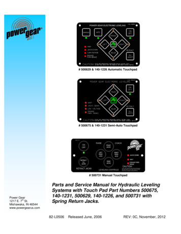
# 500629 & 140-1226 Automatic Touchpad# 500675 & 140-1231 Semi-Auto Touchpad# 500731 Manual TouchpadPower Gearth1217 E. 7 St.Mishawaka, IN 46544www.powergearus.comParts and Service Manual for Hydraulic LevelingSystems with Touch Pad Part Numbers 500675,140-1231, 500629, 140-1226, and 500731 withSpring Return Jacks.82-L0506Released June, 2006REV: 0C, November, 2012
Thank you for buying our Power Gear product! Before servicing this leveling system read this manual carefully and payattention to the "notes" and "warnings". Remember that all leveling systems can be dangerous if used improperly. Also keep inmind safety, and use the leveling system in accordance with the operating instruction manual and common sense. Thismanual has been prepared for the service of the spring return jacks leveling system. Its purpose, aside from recommendingstandard service procedures and routine service requirements, is to promote safety through the use of accepted servicepractices. Read, understand and follow the safety instructions and notes of this manual and all safety messages on thecomponents. It is recommended that all users of this equipment become familiar with the controls, components, and operationof this product before servicing the leveling system. Study this manual before servicing or operating, and keep it handy forfuture reference.TABLE OF CONTENTSPage 2:Table of ContentsPage 3:Warning/Before You Service the CoachPage 4:System DescriptionPage 5:Recommended Fluids/Preventive MaintenancePage 6:General Operation InstructionsPage 7-9:Metal Tank Hydraulic Pump AssembliesPage 10-11:Plastic Tank Hydraulic Pump AssembliesPage 12:Hose Identification GuidePage 13:Hydraulic FittingsPage14-19:Touch Pad and Control Box ConnectionsPage 20-21:Wiring DiagramsPage 22-28:Troubleshooting GuidePage 29:Warranty2
BEFORE YOU SERVICE THE COACHWARNING DO NOT USE THE POWER GEAR HYDRAULIC LEVELING SYSTEM (OR AIRSUSPENSION) TO SUPPORT VEHICLE WHILE UNDER COACH ORCHANGING TIRES. THE HYDRAULIC LEVELING SYSTEM IS DESIGNED ASA ‘LEVELING’ SYSTEM ONLY. TIRE REPAIRS SHOULD BE PERFORMED BYA TRAINED PROFESSIONAL. ATTEMPTS TO CHANGE TIRES WHILESUPPORTING THE VEHICLE WITH THE HYDRAULIC SYSTEM COULDRESULT IN DAMAGE TO THE MOTOR HOME AND/OR CAUSE SERIOUSINJURY OR EVEN DEATH. KEEP PEOPLE CLEAR OF COACH WHILE LEVELING SYSTEM IS IN USE. NEVER LIFT THE WHEELS OFF THE GROUND TO LEVEL THE COACH.DOING SO MAY CREATE AN UNSTABLE CONDITION. NEVER EXPOSE HANDS OR OTHER PARTS OF THE BODY NEARHYDRAULIC LEAKS.HIGH PRESSURE OIL LEAKS MAY CUT ANDPENETRATE THE SKIN CAUSING SERIOUS INJURY. DO NOT USE A HIGH PRESSURED WASH/RINSE SYSTEM ON ANY OF THECOMPONENTS ASSOCIATED WITH THE LEVELING SYSTEM. THISINCLUDES THE PUMP, PUMP MOTOR, WIRING HARNESS, CONTROL, ANDTOUCHPAD. THE USE OF A HIGH PRESSURE WASH/RINSE SYSTEM WILLVOID THE WARRANTY.CAUTION - PARK THE COACH ON A REASONABLY SOLID SURFACE OR THEJACKS MAY SINK INTO GROUND. ON SOFT SURFACES, USE LOADDISTRIBUTION PADS UNDER EACH JACK.CAUTION - CHECK THAT POTENTIAL JACK CONTACT LOCATIONS ARE CLEAROF OBSTRUCTIONS OR DEPRESSIONS BEFORE OPERATION.3
BEFORE YOU OPERATE THE SYSTEM:1. Make sure jack cylinder paths from the coach to the ground are clear andfree of obstructions.2. Make sure that the coach does not have objects leaning against the sides ofit. As the coach will rise when the jack cylinders engage the ground and startto lift, moving the coach.3. Place blocks under the jack cylinder foot pads for soft or low ground issues.Use as many blocks as needed to bring the depression, equal to or abovethe surrounding ground level.4
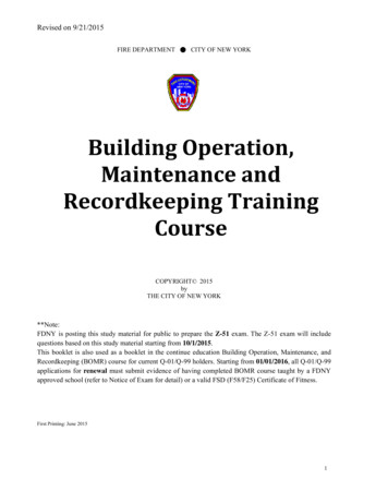
MAJOR COMPONENT DESCRIPTIONSYSTEM DESCRIPTION - The Power Gear electro-hydraulic leveling system consists of the followingmajor components:(A) Touch Pad that is located inside the cab area of the coach. The touch pad communicates the inputfunctions to the control box and receives status signals from the control. The available touch padsare: Manual touch pad (Part # 500731). Does not use a separate control box. Semi-Automatic touch pad (Part #'s 500675 or 140-1231). These use a separate control box. Automatic touch pad (Part #'s 500629 or 140-1226). These use a separate control box.(B) Control Box which has an internal leveling sensor and levels the coach to a calibrated point; it ismounted upside down inside a water proof location in the center of the coach. Contact the O.E.Mfor exact location. The control box communicates with the hydraulic pump assembly and the touchpad. A new or replacement control box does not have a stored level point; this must be set afterinstallation. See reference documents for calibration procedure. The available control boxes are: Semi-Automatic control box (Part #'s 500674 or 140-1230). Automatic control box (Part #'s 500630, 140-1227, 1010001284, 1010001002 and 9010000156).(C) Hydraulic Pump Assembly that consists of these components: motor, motor starter solenoid,pump, reservoir tank and manifold assembly. The manifold assembly has leg valve assemblies anda dump valve assembly. There is a manual override leg or dump valve with a trailer style connectoror a packard style connector. There is also a non-override leg or dump valve with a trailer styleconnector or a packard style connector.(D) Hydraulic Hoses are used to connect the hydraulic pump assembly to the jack leg cylinders. Thehoses are rated according to the output pressure of the pump assembly.(E) Jack Leg Cylinders with either internal or external springs that are rated at a lifting capacityappropriate for your coach. Each jack has a large 10" diameter (78.5 square inch) shoe formaximum mating area on different surfaces. External spring jacks have a spring that is mountedexternally and connected both to the top at the jack bracket and to the shoe of the jack. Internalspring jacks have a spring welded to the inside top of the jack and connected to the top of thechrome rod.D) Hydraulic HosesItem AC) Hydraulic Pump AssemblyE) Jack Leg Cylinders5Item BTouch Pad and Control Box
RECOMMENDED HYDRAULIC FLUIDSThe fluids listed here are acceptable to use in your pump assembly. Contact the coach manufactureror selling dealer for information about what specific fluid was installed in your system.Please consult factory before using any other fluids.In most applications, Type A automatic transmission fluid (ATF, Dexron III, etc.,) will work satisfactorily. Mercon V is also recommended as an alternative fluid for Power Gear leveling systemsoperating in environments with large temperature swingsOperating in cold temperatures (less than -10 F) may cause the jacks to extend and retract slowly. Forcold weather operation, fluid specially-formulated for low temperatures may be desirable, Mobil DTE 11M, Texaco Rando HDZ-15HVI, Kendall Hyden Glacial Blu, or any Mil. Spec. H5606hydraulic fluids are recommended for cold weather operation.PREVENTATIVE MAINTENANCE PROCEDURESTo retain the quality for the leveling system use genuine Power Gear parts and service assistance. Forthe correct part or information for a particular leveling system always mention the part number listed onthe major components label before contacting Power Gear or the OE.M. Also know the year, make,and model of the RV you are working on for further assistance.WARNING:Your coach should be supported at both front and rear axles with jack stands beforeworking underneath, failure to do so may result in personal injury or death.1. Check the fluid level every month. Fill the reservoir with the jacks in the fully retractedposition. On vertical pump assemblies, the fluid should be within 1/4 inch of the fill port lipand checked only with all jacks retracted. On horizontal pump assemblies, the fluid levelshould be up to the weep hole on the side of the reservoir tank and checked only with alljacks retracted.2. Change fluid every 24 months.3. Inspect and clean all hydraulic pump electrical connections every 12 months.4. Remove dirt and road debris from jacks as needed.5. If jacks are down for extended periods, it is recommended to spray exposed chrome rodswith a silicone lubricant every seven days for protection. If your coach is located in a saltyenvironment (within 60 miles of coastal areas), it is recommended to spray the rods every 2to 3 days.6. Jacks equipped with grease fittings at the bottom of the cylinder should be greased withlight weight lithium grease using a hand pump style grease gun only. 2 or 3 pumps shouldbe sufficient for every 20-30 uses.7. Do not use a high pressured was/rinse system on any of the components associated with theleveling system. This includes the pump, pump motor, wiring harness, control and touchpad.THE USE OF A HIGH PRESSURE WASH/RINSE SYSTEM WILL VOID THE WARRANTY.6
GENERAL OPERATING INSTRUCTIONSTO EXTEND THE JACKS:1. Start the engine of the coach; this will insure proper voltage to the fuse which feeds the motorstarter solenoid and control box. This fuse is provided by the O.E.M.; contact them for locationand size. The batteries provide voltage to the hydraulic pump assembly and control box forcorrect operation. Some controls require a minimum of 13.1VDC to come out of "WAIT"mode.2. Power the touch pad on by pressing the ON/OFF button. The LED will light up under thebutton indicating the touch pad is on. The touch pad will communicate with the control box topower the touch pad on; the control box will now be ready to accept the next input function.3. Choose the function of manually leveling (MAN button) or automatically leveling (AUTObutton) the coach by selecting the corresponding button. Press the AUTO button and it will dump the air (if using the 4 pin AUX connector on thecontrol box, and it is programmed accordingly) and the system will level the coach to thecalibrated point stored in the control box. Press and hold the MAN button for 5 seconds until the LED is lit under the button and it willdump the air (if using the 4 pin AUX connector on the control box, and it is programmedaccordingly). Use the 4 directional buttons to extend the jacks. Pressing right button willoperate the right rear jack; pressing left button will operate the left rear jack. Pressing thefront button will operate both front jacks. Pressing the rear button will operate both rearjacks. The touch pad communicates with the control box to energize the leg valve(s) to extend thejack(s) and level the coach.4. Turn off the touch pad. The touch pad stops communicating with the control box.5. Turn off the ignition. The control box removes the power for the touch pad.TO RETRACT THE JACKS:1. Start the engine of the coach, this will insure proper voltage to the fuse which feeds the motorstarter solenoid and control box. This fuse is provided by the O.E.M.; contact them for locationand size.2. Power the touch pad on by pressing the ON/OFF button. The LED will light up under thebutton indicating the touch pad is on. The touch pad will communicate with the control box,and will now be ready to accept the next input function from the touch pad.3. Press and release the RETRACT ALL JACKS button. The touch pad communicates with thecontrol box to energize the leg valves and the dump valve on the hydraulic pump assembly.The jack springs pull on the foot pads and push the fluid back into the reservoir tank of thehydraulic pump assembly.4. When the jacks are fully retracted the "jacks down" light on the touch pad will go off. When thefloat switch rises to the "open" position in the reservoir tank of the pump assembly, this iscommunicated to the control box, which then turns off the jacks down light on the touch padwithin 20-30 seconds.7
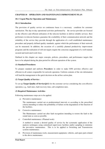
VERTICAL METAL TANK PUMP ASSEMBLIES2003 - 20081102113948675ITEMPART ESCRIPTIONComplete power unit (1.5 gal. capacity)Complete power unit w/manual override knob on end of valvesComplete power unitComplete power unitValve manifold assembly (used w/ pump # 500893)Valve manifold assembly (used w/ pump # 500721)Valve manifold assembly (used w/ pump # 500911)Valve manifold assembly w/manual override valves (used w/ 500888)2800302Motor Bearing4800036STank replacement service kit (2.0 gal only)07-1238130-1214130-1214030-104007-1239Fill plugBreather cap/dip stick (used with pump # 500911 only)Push-in breather cap and dipstickGrommet, push-in breather capDrain plugSee T.I.P. sheet 82-L0512 for fluid sensor/float switch IDSee T.I.P. sheet 82-L0509 and 82-L0510 for testing the fluid sensor orfloat switchPump harnessPump harness w/packard connectorDump valve assembly w/o manual overrideDump valve assembly w/manual override knob on end of valvesMotor starter solenoidAir breatherPump/motor assembly (used with pump assembly # 500893) (obsolete)Pump/motor assembly (used with pump assembly # 500721)Pump/motor assembly (used with pump assembly # 500888) (obsolete)Pump/motor assembly (used with pump assembly # 500911) (obsolete)Leg valve assembly w/trailer connectorLeg valve assembly w/packard connector and manual override knob onend of valve1 - 118, 96571110131, 2, 4, 5, 38130-1162130-11895000995004398QTYAPPLICATION12003 - 200811999 - present12003 - present11999 - present11999 - present111999 - 20081112003 - present11994 - present1111111999 - present1999 - 20081999 - 20082003 - present2003 - 20052003 - 200831994 - present
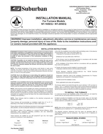
HORIZONTAL METAL TANK PUMP ASSEMBLIES2003 - 200664132Weep HoleTHE DIFFE RE NCE IS IN THE DETAILSHYDRAULIC POWER UNIT5level 9P/N:SIZ E:S/N:MISHAWAKA, INDIANA500812“A”8ITEMPART 05000975004407DESCRIPTIONComplete 3-valve pump assy.1.0 gal. capacity w/manual override knob on end of valves (obsolete)1.6 gal. capacity w/manual override knob on end of valves1.0 gal. capacity w/o manual override valves (obsolete)Complete 4-valve pump assy.1.5 gal. capacity w/o manual override valves (obsolete)1.0 gal. capacity w/o manual override valves (obsolete)1.4 gal. capacity w/o manual override knob on end of valves1.4 gal capacity w/manual override knob on end of valves (obsolete)1.0 gal capacity w/manual override knob on end of valves1.4 gal capacity w/manual override knob on end of valvesManifold assembly w/manual override valvesManifold assy. pump #’s 500773 & 500781Manifold assy. pump #’s 500925 & 501000Manifold assy. pump # 501013Manifold assembly w/o manual override valvesManifold assy. pump #’s 500910 and 500920Leg valve assembly w/trailer connectorLeg valve assembly w/packard connector and manual override knob onend of valveSee T.I.P. sheet 82-L0512 for fluid sensor/float switch IDSee T.I.P. sheet 82-L0511 for testing the fluid sensor or float switchBreather cap and dipstickPush-in breather cap and dipstick (pump assy. 500781)Grommet, push-in breather cap1.0 gal. reservoir (obsolete)1.4 gal. reservoir (obsolete)Pump harnessMotor Bearing onlyPump/motor assy. for power unit assy’s 500773 and 500825Pump/motor assy. for power unit assy 500781Pump/motor assy. for power unit assy’s 500910 and 501000 (obsolete)Pump/motor assy. for power unit assy’s 500920 and 500925Motor starter solenoidDump valve assembly w/o manual overrideDump valve assembly w/manual override knob on end of valves9“A”QTY11.0”9.0”11.0”1112003 - present2003 - 20062002 - 952003 - 20062003 - 20062003 - 20062004 - 20062004 - 20061112003 - present2003 - present2004 - present1332003 - present1994 - present111111111111111APPLICATION1994 - present2002 - present2003 - present2003 - present2003 2003 2002 - present2002 - present2003 - 20052003 - 20052003 - 20082003 - present1994 - present1994 - present1994 - present
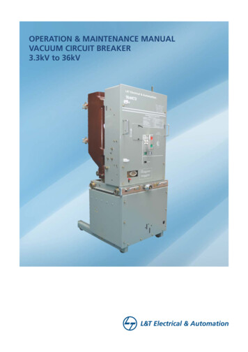
3 OR 4 JACK LEG VALVE ASSEMBLY1999 - PRESENTValve manifold assemblyITEM1,3,41,3,6581-7PART 4500772500960500959DESCRIPTIONRear hose connector kitFront hose connector kitLeg valve assembly w/trailer connector (Shown)Leg valve assembly w/packard connector and manual override knobon end of valve (Not shown)O-ring kitValve manifold assembly, pump # 500893Valve manifold assembly, pump # 500721Valve manifold assembly, pump # 500888Valve manifold assembly, pump # 500773 & 500781Valve manifold assembly, pump # 500925 & 501000Valve manifold assembly, pump # 501013*”F” port has 2 springs10QTY1111APPLICATION1999 - present1999 - present1994 - present111999 - present1999 - present12003 - present
VERTICAL PLASTIC TANK PUMP ASSEMBLIES17863452ITEMPART #1-835100001593510000160351000016135100001626, 86, 86, -10405Not shown500335Not DESCRIPTIONComplete 4-valve pump assembly1.5 gal. capacity w/manual override knob on end of valves1.5 gal. capacity w/manual override knob on end of valves1.5 gal. capacity w/manual override knob on end of valves1.5 gal. capacity w/manual override knob on end of valvesManifold assembly w/manual override valvesValve manifold assembly (used w/ pump # 3510000159)Valve manifold assembly (used w/ pump # 3510000160)Valve manifold assembly (used w/ pump # 3510000161 and 3510000162)Motor and bearingFor plastic tank replacement kit information see T.I.P. sheet 82-L0518Push in breather capGrommet, push in breather capSee T.I.P. sheet 82-L0512 for fluid sensor/float switch IDSee T.I.P. sheet 82-L0509 and 82-L0510 for testing the fluid sensor or floatswitchPump harness w/trailer style connector (for pump assy. # 3510000159)Pump harness w/packard style connector (for pump assy. # 3510000160,3510000161 and 3510000162)Dump valve assemblyDump valve assembly w/packard style connectorMotor starter solenoidQTYAPPLICATION11112008 - present2008 - present2008 - present2008 - present111111112004 - present2007 - present2007 - present1999 - present2012 - present2007 - present2004 - present111997 - present12007 - present1112006 - present2006 - present1999 - present2008 - presentPump /motor / tank assy.1500099Leg valve assembly w/trailer connector31994 - present500439Leg valve assembly w/packard connector and manual override knob on endof valve31994 - present11
HORIZONTAL PLASTIC TANK PUMP ASSEMBLIES48356217ITEM1-8PART 1976,81231010000991800302453010001126030-1040Not shown141-0015016Not 1000001135100001438500439Not shown6DESCRIPTIONComplete 4-valve pump assy.2.0 gal. capacity w/manual override knob on end of valves2.0 gal. capacity w/manual override knob on end of valves2.0 gal. capacity w/manual override knob on end of valves1.5 gal. capacity w/manual override knob on end of valvesManifold assembly w/manual override valvesValve manifold assembly (used w/pump # 1010000917)Valve manifold assembly (used w/pump # 1010000918 and3510000013)Valve manifold assembly (used w/pump # 3510000152)Motor and bearingFor plastic tank replacement kit information see T.I.P. sheet 82-L0518See T.I.P. sheet 82-L0512 for fluid sensor/float switch IDSee T.I.P. sheet 82-L0511 for testing the fluid sensor or float switchPush in breather capGrommet, push in breather capPump harness (used on pump assemblies # 1010000917,3510000013)Pump harness (used on pump assembly 1010000918)Pump harness (used on pump assembly 3510000152)Dump valveDump valve w/packard connectorMotor starter solenoidPump /motor / tank assy. (2.0 gal)Pump /motor / tank assy. (1.5 gal)Leg valve assembly (09-1140 and 09-1139)Leg valve assembly w/packard connector and manual override knobon end of valve12QTYAPPLICATION11112007 - present2007 - present2006 - present2008 - present12003 - present12003 - present1112007 - present1999 - present2012 - present112007 - present2004 - present12004 - present111111132005 - present2007 - present2006 - present2006 - present1999 - present2006 - present2008 - present31994 - present
HOSE IDENTIFICATION GUIDE1/4" Hose #080-XX XXX - IIHose fitting at each endLetterABCDEFGDefinition#4 37 deg female swivel end, 7/16-20 thread perS.A.E. J514/J.I.C#6 37 deg female swivel end, 9/16-18 thread perS.A.E. J514/J.I.C90 deg short bend tube, #4 37 deg female swivel7/16-20 thread per S.A.E. J514/J.I.C90 deg short bend tube, #6 37 deg female swivel9/16-18 thread per S.A.E. J514/J.I.C45 deg short bent tube, #4 37 deg female swivel7/16-20 thread per S.A.E. J514/J.I.C#4 37 deg male rigid end 7/16-20 thread per S.A.E.J514/J.I.C#6 37 deg male rigid end 9/16-18 thread per S.A.E.J514/J.I.CExample: Hose assembly # 080-AA264-II: The 080 indicates a 1/4" hose diameter "AA" indicates it uses a # 4 37 deg femaleswivel end fittings on both ends. The overall length of the hose is 264" long.3/8" Hose #08- X XXX X XXCR Curbside RearCF Curbside FrontRR Roadside RearRF Roadside FrontHose fitting at each endLetterABCDEFGT TopB BottomN N/ADefinition#4 37 deg female swivel end, 7/16-20 threadper S.A.E. J514/J.I.C#6 37 deg female swivel end, 9/16-18 threadper S.A.E. J514/J.I.C90 deg short bend tube, #4 37 deg femaleswivel 7/16-20 thread per S.A.E. J514/J.I.C90 deg short bend tube, #6 37 deg femaleswivel 9/16-18 thread per S.A.E. J514/J.I.C45 deg short bent tube, #4 37 deg femaleswivel 7/16-20 thread per S.A.E. J514/J.I.C#4 37 deg male rigid end 7/16-20 thread perS.A.E. J514/J.I.C#6 37 deg male rigid end 9/16-18 thread perS.A.E. J514/J.I.CExample: Hose assembly # 08-A360TRR: The 08 indicates 3/8" hose diameter "A" indicates it uses a #4 37 deg femaleswivel end fittings on both ends The overall length of the hose is 360" long TRR indicates it connects to the top port ofthe roadside rear jack.13
HYDRAULIC 0-1268WO11380070-1262Reducers:070-1263070-125814
MANUAL TOUCH PAD CONTROL500731 touchpad control (front view)2004-Present500731 touchpad control (rear view)123ITEMNOTE1Not shownPART #DESCRIPTIONQTYAPPLICATION12004 - present12004 - present12004 - present5013-161Auxiliary harness connector5021-XXXPump harness connectorNot shown2141-0005XXXPump harness (with fuse)5010-XXXNot shown3Main power connector5018-XXX“-XXX” length of harness in inchesNote: See TIP Sheet # 204 for calibration instructions.Item #1 – Auxiliary Harness ConnectorItem #3 – Main Power ConnectorPin #1Pin #2Pin #3Pin #4Fill output to the airbag valve. Energized with 12vdc tofill airbags.Fill output to the airbag valve. Ground to fill airbags.Dump output to the airbag valve. Energized with 12vdcto dump airbags.Dump output to the airbag valve. Ground to dumpairbags.Item #2 – Pump Harness ConnectorPin #1Pin #2Pin #3Pin #4Pin #5Pin #6Pin #1Pin #2Pin #3Pin #4Pin #5Pin #6Pin #7Pin #8Ground input.Float switch input. See TIP sheets 82-L0509, 82-L0510and 82-L0511 to determine proper signals.Output to motor starter solenoid. Energized with 12vdcwhen the front/rear/left/right button(s) are pushed.Output to dump valve. Energized with 12vdc when the"retract all jacks" button is pushed.Output to roadside rear leg valve. Energized with 12vdc when left or rear button or retract button ispushed.Output to curbside rear leg valve. Energized with 12vdc when right or rear button or retract button ispushed.Output to front jack leg valve. Energized with 12vdcwhen front button or retract button is pushed.Input from motor starter solenoid. Energized with 12vdc to supply power to the touchpad control15Input from park brake. Has continuity toground when the park brake is engaged.Input from neutral safety switch. Canmeasure as either 12vdc or ground.Not used.Not used.Input from ignition. Energized with 12vdc when the coach is running.Input from neutral safety switch. Canmeasure as either 12vdc or ground.
SEMI-AUTOMATIC TOUCHPAD & CONTROLS500675 touchpad Obsolete – use 500675S kit2002-2005500674 control box Obsolete – use 500674S kit1342ITEMNOTEPART #DESCRIPTIONQTYAPPLICATION5020-XXXNot shown1Main power connector12002 - present5018-XXXNot shown25019-XXX Touch pad harness connector Obsolete12002 - 2005Not shown 5013-1613Auxiliary harness connector12002 - presentNot shown 5021-XXX4Pump harness connector12002 - presentSemi-auto control kit (touchpad, control box, touchpad harness)5006732002 - presentNote: See TIP Sheet # 152 for calibration instructions.“-XXX” length of harness in inchesItem #1 – Main Power ConnectorItem #3 – Auxiliary Harness ConnectorPin #1Pin #2Pin #3Pin #1Pin #2Pin #3Pin #4Pin #5Pin #6Input from park brake. Hascontinuity to ground when the parkbrake is engaged.Input from neutral safety switch.Can measure as either 12vdc orground.Not used.Not used.Input from ignition. Energized with 12vdc when the coach is running.Input from neutral safety switch.Can measure as either 12vdc orground.Pin #4Pin #1 Output to thetouchpad. Transmitsignal 5-7vdc.Pin #2 Input from thetouchpad. Receivesignal 5-7vdc.Pin #3 Power ( 12vdc) outputto the touchpad.Pin #4 Ground output to thetouchpad.Dump output to the airbag valve. Energized with 12vdc todump airbags.Dump output to the airbag valve. Ground to dumpairbags.Item #4 – Pump Harness ConnectorPin #1Pin #2Pin #3Pin #4Item #2 – Touch Pad Harness ConnectorFill output to the airbag valve. Energized with 12vdcto fill airbags.Fill output to the airbag valve. Ground to fill airbags.Pin #5Pin #6Pin #7Pin #8Ground input.Float switch input. See TIP sheets 82-L0509, 82-L0510 and 82L0511 to determine proper signals.Output to motor starter solenoid. Energized with 12vdc whenthe front/rear/left/right button(s) are pushed.Output to dump valve. Energized with 12vdc when the "retractall jacks" button is pushed.Output to roadside rear leg valve. Energized with 12vdc whenleft or rear button or retract button is pushed.Output to curbside rear leg valve. Energized with 12vdc whenright or rear button or retract button is pushed.Output to front jack leg valve. Energized with 12vdc when frontbutton or retract button is pushed.Input from motor starter solenoid. Energized with 12vdc tosupply power to the touchpad control16
SEMI-AUTOMATIC TOUCHPAD & CONTROL 2006-Present140-1231 touchpadITEMNOTE140-1230 control boxPART #1324DESCRIPTIONQTYAPPLICATION5020-XXXNot shown1Main power connector12002 - present5018-XXXNot shown 141-0045XXX2Touch pad harness connector12005 - presentNot shown 5013-1613Auxiliary harness connector12002 - presentNot shown 5021-XXX4Pump harness connector12002 - presentSemi-auto control kit (touchpad, control box, touchpad harness)5006732002 - presentNote: See TIP Sheet # 152 for calibration instructions.“-XXX” length of harness in inchesItem #1 – Main Power ConnectorPin #1Pin #2Pin #3Pin #4Pin #5Pin #6Input from park brake. Hascontinuity to ground when the parkbrake is engaged.Input from neutral safety switch.Can measure as either 12vdc orground.Not used.Not used.Input from ignition. Energized with 12vdc when the coach is running.Input from neutral safety switch.Can measure as either 12vdc orground.Item #3 – Auxiliary Harness ConnectorPin #1 Fill output to the airbag valve. Energized with 12vdc tofill airbags.Pin #2 Fill output to the airbag valve. Ground to fill airbags.Pin #3 Dump output to the airbag valve. Energized with 12vdc to dump airbags.Pin #4 Dump output to the airbag valve. Ground to dumpairbags.Item #4 – Pump Harness ConnectorPin #1Pin #2Pin #3Pin #4Item #2 – Touch Pad Harness ConnectorPin #5Pin #6Pin #1 – Output to the touchpad.Pin #1 Output to the touchpad. TransmitTransmit signal 5-7vdc.signal 5-7vdc.Pin #2 – Input from the touchpad.Pin #2 Input from the touchpad. ReceiveReceive signal 5-7vdc.signal 5-7vdc.Pin #3 – Power ( 12vdc) output toPin #3 Power ( 12vdc) output to thethe touchpad.touchpad.Pin #4 – Ground output to thePin #4 Ground output to the touchpad.touchpad.Pin #7Pin #8Ground input.Float switch input. See TIP sheets 82-L0509, 82-L0510 and 82L0511 to determine proper signals.Output to motor starter solenoid. Energized with 12vdc whenthe front/rear/left/right button(s) are pushed.Output to dump valve. Energized with 12vdc when the "retractall jacks" button is pushed.Output to roadside rear leg valve. Energized with 12vdc whenleft or rear button or retract button is pushed.Output to curbside rear leg valve. Energized with 12vdc whenright or rear button or retract button is pushed.Output to front jack leg valve. Energized with 12vdc when frontbutton or retract button is pushed.Input from motor starter solenoid. Energized with 12vdc tosupply power to the touchpad control17
AUTOMATIC TOUCH PAD & CONTROL2002-2005500630 control box Obsolete – use 500630S500629 touchpad Obsolete – use 500629S1342ITEMNOTE12Not shownNot shownPART #DESCRIPTIONQTYAPPLICATION5020-XXXMain power connector12002 - present5019-XXXTouch pad harness connector Obsolete12002 - 2005500771Not shown 5007873Auxiliary harness connector12002 - present5013-XXXNot shown 5021-XXX4Pump harness connector12002 - presentAutomatic control kit (touchpad, control box, touchpad harness)500643s12002 - present“-XXX” length of harness in inchesNote: See TIP Sheet # 153 for calibrationItem #1 – Main Power ConnectorPin #1Pin #2Pin #3Pin #4Pin #5Pin #6Input from park brake. Hascontinuity to ground when the parkbrake is engaged.Input from neutral safety switch.Can measure as either 12vdc orground.Not used.Not used.Input from ignition. Energized with 12vdc when the coach is running.Input from neutral safety switch.Can measure as either 12vdc orground.Item #3 – Auxiliary Harness ConnectorPin #1 Fill output to the airbag valve. Energized with 12vdc tofill airbags.Pin #2 Fill output to the airbag valve. Ground to fill airbags.Pin #3 Dump output to the airbag valve. Energized with 12vdc to dump airbags.Pin #4 Dump output to the airbag valve. Ground to dumpairbags.Item #4 – Pump Harness ConnectorPin #1Pin #2Pin #3Pin #4Item #2 – Touch Pad Harness ConnectorPin #5Pin #1 Output to the touchpad.Transmit signal 5-7vdc.Pin #2 Input from the touchpad.Receive signal 5-7vdc.Pin #3 Power ( 12vdc) outputto
of this product before servicing the leveling system. Study this manual before servicingor operating , andkeep it handy for future reference. TABLE OF CONTENTS . Page 2: Table of Contents . Page 3: Warning/Before You Service the Coach . Page 4: System Description . Page 5: Recommended Fluids/Preventive Maintenance