Transcription
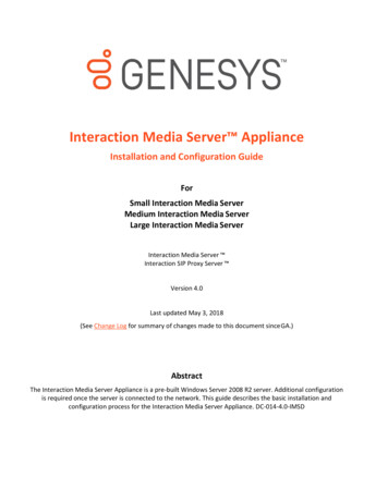
Journal of Superconductivity and Novel Magnetism (2022) 6286-6ORIGINAL PAPERCoulomb Interaction Engineering at YBa2Cu3O7 ı‑SrTiO3 InterfaceF. La Mattina1· R. Erni1 · M. D. Rossell1 · G.‑L. Bona1 · A. Shengelaya2,3Received: 28 March 2022 / Accepted: 10 May 2022 / Published online: 10 June 2022 The Author(s) 2022AbstractIt has been proposed by Müller and Shengelaya that underdoped ultrathin layers of copper-oxide high-temperature superconductors (HTSs) sandwiched between high-dielectric-constant insulator layers could manifest increased superconductingcritical temperature Tc. To check this hypothesis, we investigated structural and transport properties of YBa2Cu3O7 𝛿 (YBCO)thin films sandwiched between SrTiO3 (STO) layers. Scanning transmission electron microscopy (STEM) showed that ahigh-quality interface is formed between YBCO and the top STO layers. An increase of Tc up to ΔT 20 K was observed atthese interfaces in case of underdoped YBCO films.Keywords HTC · Cuprates · Dielectric · Epitaxial thin film · Transition metal oxides · Interface · Coulomb engineeringPACS 74.20.-z · 74.62.-c · 74.62.Dh · 74.72.-h · 74.78.Bz · 74.90. n1 IntroductionThe HTSs based on hole-doped cuprate oxides have an universal doping dependence for the superconducting transition temperature (Tc) [2] showing a maximum at the optimaldoping of about 15 mol%. In these compounds, it has beenproposed that Jahn-Teller intersite bipolarons aggregate toform metallic clusters (or stripes) [3–7]. When a critical distribution of these clusters is reached, percolation takes placeand the bulk superconducting phase is established [5, 8].According to this model, opening of the so-called pseudogap(T ) has been proposed to be associated with the formation ofsuch clusters, which locally host the superconducting phase.These are charged regions that form and dissociate basedIn this paper we review the results of studies initiated under theguidance of Prof. K. A. Müller, who motivated us to implementthe heterostructure that he proposed in his paper together withA. Shengelaya [1]. He actively participated in this project, followingregular meetings every month for about one year.* F. La Mattinafabio.lamattina@empa.ch1Empa, Swiss Federal Laboratories for Materials Scienceand Technology, Überlandstrasse 129, 8600 Dübendorf,Switzerland2Department of Physics,, Tbilisi State University,Chavchavadze 3, GE‑0128 Tbilisi, Georgia3Ivane Javakhishvili Tbilisi State University, AndronikashviliInstitute of Physics, 0177 Tbilisi, Georgiaon thermal fluctuations, and the Coulomb repulsion betweenthese objects (see Fig. 1a) prevents from reaching percolation [7]. Therefore, in 2013 Müller and Shengelaya [1] proposed to apply the method of “Coulomb interaction engineering” [9] in ultrathin layers of copper-oxide HTSs sandwichedbetween high-dielectric-constant insulators(see Fig. 1b). TheCoulomb repulsion between the clusters could be reduceddue to the penetration of the electric field from the surrounding insulators with high dielectric constant. This might resultin a smaller distances between the charged clusters and thushelp to form a 3D percolation at higher temperatures, leadingto a higher Tc.The possibility to modify the Coulomb interaction in athin layer of a semiconductor or semimetal was pointed outfor the first time by Keldysh [9]. Other authors showed howthe dielectric mismatch of substrate and semiconductor layercould decrease the scattering term of Coulomb impurities,i.e., producing an improvement in mobility of carriers [10]or can be used for band gap tuning [11, 12].Despite the simple idea behind the proposed oxide-HTSoxide heterostructure, there are several challenges to create high-quality epitaxial interfaces. Superconductivity atinterfaces is sensitive to many factors that can reduce Tc oreven suppress the superconductivity: cation inter-diffusion,surface reconstruction caused by polar discontinuity, oxygenion mobility at the interface, structural defects and straineffects due to lattice mismatch.13Vol.:(0123456789)
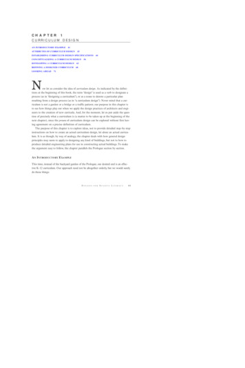
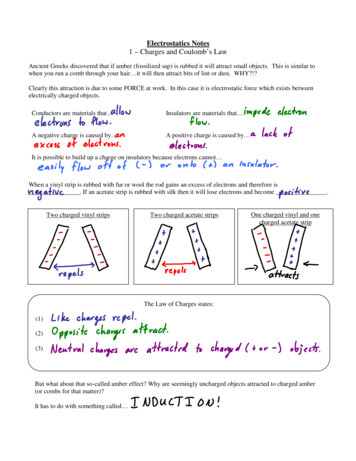
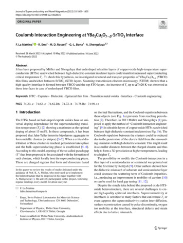
1802Journal of Superconductivity and Novel Magnetism (2022) 35:1801–1805(b)(a)Fig. 1 a Schematic drawing of charged clusters or stripes appearingbelow T (adapted from ref.[3]). b Schematic representation of theheterostructure proposed by Müller and Shengelaya [1] where a thinfilm of cuprate HTS is sandwiched between high-dielectric insulatorsTo search for the possible dielectric enhancement of Tc ,we prepared multilayer YBCO-STO heterostructures andstudied their structural and transport properties.2 Materials and MethodsCommercial (CRYSTAL, GmbH) high-quality singlecrystalline (001)-oriented STO with a miscut angle 0.1 was used as a substrate for films growth. Step-like TiO2-terminated surfaces were obtained by a standard HF etching and oxygen annealing procedure as reported in Ref.[13]. Nominally pure YBa2Cu3O7 𝛿 films were grown fromcommercial ceramic target by means of pulsed laser deposition (PLD) setup which uses a KrF (248 nm) excimerlaser (Coherent LPX 300i). All the films were grown under100 mTorr oxygen pressure at 780 C with a laser fluencyof 1.25 J/cm2 at 1 Hz. After the deposition, three differentin situ annealing procedures were used to achieve different levels of oxygen doping. The cooling rate and partialpressure of O 2 were selected as shown in Table 1 between600 C and room temperature.X-ray diffraction (XRD) experiments were performed ona Bruker D8 Discover, with a CuK𝛼 tube (𝜆 1.5406 Å).Indium wires pushed on the YBCO surface were connectedin a typical 4 probe geometry with additional drops of Agpaint to guarantee a good electrical contact. In case of aSTO top layer, a simple mechanical scratch by means ofa diamond tip ensures the electrical contact to the bottomYBCO layer via the Ag paint. High-resolution images ofthe top surface were taken by means of an ORION He ionmicroscope (HIM) from Carl Zeiss (henceforth referred toas “He-microscope”). This microscope is based on a Hefocused ion beam (FIB) that excites secondary electrons inthe sample, which are then detected for image formation.We operated it with a beam current of 0.5 pA and 30 kVaccelerating voltage. The film microstructures were characterized using a transmission electron microscope (TEM,JEOL 2200FS) operated at an accelerating voltage of 200 kVin scanning transmission mode using a high-angle annulardark-field detector. Lamellas for TEM analysis were prepared by Ga-focused ion beam instrument (FEI Strata 235).3 Results and Discussion3.1 Crystal Quality of YBCO‑STO InterfacesXRD measurements performed on our YBCO films showonly (00l) reflections, which implies that the films are c-axisoriented, as shown on a selected sample in Fig. 2.He-ion secondary electron emission imaging performedon the top surface (Fig. 3a) of a thick optimally dopedYBCO film ( 165 nm) shows evidence of a mosaic of rectangular domains. This texture is a consequence of the distribution of orientations of the ab plane of YBCO whichform in different nucleation points during the growth of thefirst YBCO layer.Therefore, 90 twinned domains [14] form on top of aTiO2-terminated STO surface which has a 4 fold symmetry. For thin films below 50 nm (Fig. 3a) this texture isless evident. Here, the surface is smoother and more flatindicating that, in this range of thickness, a layer-by-layerTable 1 In situ YBCO annealing (600 C 30 C)Optimally dopedUnderdoped IUnderdoped II13O2Coolingrate( /min)0.5 atm100 mTorr100 mTorr15 20 CFig. 2 XRD pattern shows only (00l) reflections line of the YBCO(blue) which grows coherently to the [001] SrTiO 3 (red) direction
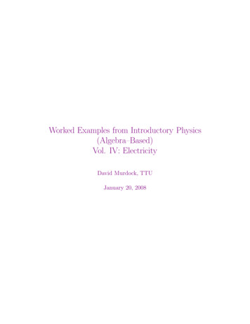
Journal of Superconductivity and Novel Magnetism (2022) 35:1801–1805Fig. 3 He-FIB images of bare YBCO film on STO substrate with athickness of a 165 nm and b 50 nm. Here, 90 twinned domains [14]form on top TiO 2 -terminated STO surface which has a 4 fold symmetry. This tower-like growing becomes less evident for the thinnersample which has a smoother surfacegrowth (Frank–van der Merwe mode) dominates the deposition instead of a tower-like mode (Stranski–Krastanovgrowth). The latter gives rise to a difference in the heightbetween the twinned domains which is undesired for theformation of good interfaces.The quality of epitaxial YBCO thin films reported inthe literature depends on the growing techniques. It wasreported that thin films produced by magnetron sputteringare superconducting down to 2 unit cell (UC) layers [15],while in the case of PLD superconductivity is suppressedbelow 6 UC layers [16].Other works [17, 18] addressed the so-called dead layers of YBCO at the interface with STO as the main responsible of suppression of Tc . These layers originate from thelattice mismatch between the STO (a 3.905 Å, cubic) andthe c-axis of YBCO (c 11.70 Å) as shown in Fig. 4a. TheTiO2-terminated atomically flat STO substrate containssteps between each TiO2 terraces, with a minimal heightcorresponding to its lattice parameter (3.905)Å which isabout 1/3 of the c-axis unit cell parameter of YBCO. Thismismatch generates anti-phase boundaries into the film(see schematic representation in Fig. 4c) which could beresponsible for the suppression of the superconductivity ina few layers from the bottom interface [17, 18]. However,this difference of the lattice parameters between the twocompounds does not generate defects in the STO-YBCOtop interface (Fig.4b), because 3(n) UCs of STO can coverand adapt to each steps on the YBCO surface as shownschematically in Fig. 4d. In order to implement the heterostructure proposed by Müller and Shengelaya [1], itis clear from our findings that YBCO films must be sufficiently thick in order to avoid the initial 5 to 6 “deadlayers,” but thinner than 50 nm in order to obtain a goodinterface with the STO deposited. Only the top interface(almost defect free) could be eligible for “Coulomb interaction engineering” effects.1803(a)(b)(c)(d)Fig. 4 STEM images of (a) bottom YBCO-STO (substrate) and (b)top STO-YBCO interfaces and their schematic representations (c) and(d), respectively3.2 Transport Measurements of Optimally DopedYBCO‑STO HeterostructuresWe have performed investigation on a series of optimallydoped YBCO films with and without STO cap layers. Thesuperconducting critical temperature Tc was extracted by theonset of resistance drop (see Fig. 5a). The films with thickness from 165 nm down to 11 nm do not show any substantialeffect on Tc when top layers of STO were present (see inset inFig. 5a). The quality of our epitaxial films down to a thickness of about 11 nm (with Tc 87 K) compares well withhigh-quality films produced by means of magnetron sputtering (see Fig. 5b) by Barriocanal et al. [15], while in case ofPLD other authors report a decrease of Tc to about 65 K at11nm [16]. The difference with our case could originate fromthe quality of the substrates selected for the growth. Indeed,the miscut angle of the substrate determines the amount ofdefects (surface steps) at the interface with YBCO grownonto the STO substrates as shown by TEM (Fig. 4a).According to Müller and Shengelaya [1] the effect of thedielectric constant 𝜖 of the insulator on Tc should be largerin the underdoped region where the pseudogap temperatureis higher. Thus, it is not surprising that for the optimallydoped films we did not detect Tc enhancement due to theSTO cap layer.3.3 Transport Measurements of UnderdopedYBCO‑STO HeterostructuresWhile the slow cooling in a higher O2 pressure ( 380 Torr)ensures the oxidation of the YBCO films (optimally doped),the two fast cooling with rates (5 /min and 20 /min) in13
1804Journal of Superconductivity and Novel Magnetism (2022) 35:1801–1805Fig. 5 a Normalized resistancevs temperature of STO-YBCOoptimally doped films withdifferent thickness. The insetshows the comparison of theresistance for two YBCO films(11 nm) with and without STOtop interface. b Tc vs YBCOthickness for optimally dopedYBCO-STO (red closed circles)and STO-YBCO-STO (blueclosed triangles). The pictureincludes data extracted fromother papers where the filmswere produced by magnetronsputtering [15] (open circles)and PLD [16] (black closedcircles)(a)100 mTorr of O 2 induces oxygen vacancies (Vo s) in theYBCO layer (Table 1). Therefore, underdoped YBCO thinfilms can be obtained by fast cooling in a reduced O 2 pressure. A series of YBCO (20 nm) films with and withoutSTO cap layer of 30 nm (Fig. 6a) were grown and thermallytreated according to the annealing schemes described above.Figure 6b shows resistivity curves for YBCO thin films(underdoped II in Table 1) with and without top STO layer.For comparison, in the same figure we included resistivity dataextracted from Ref. [19] of YBCO thin films with differenthole dopings. The curves with lower resistivity and higher Tccorrespond to the optimally doped samples. In our case thehigher resistivity and lower Tc is a clear evidence of underdopedYBCO films. Under same annealing conditions the bare YBCOfilm shows a similar resistivity (red line) at room temperatureas compared with STO-capped film (blue line).(b)This indicates that both samples are underdoped withsimilar charge carrier concentrations. At the same time, asignificant increase of Tc 10 K is observed in a YBCO filmwith top STO layer, as can be seen in Fig. 6b. We measured enhancement of Tc up to 20 K in STO-capped YBCOfilms compared to the bare films. The observed increaseof Tc at the STO-YBCO interface is interesting and is consistent with the effect predicted by Müller and Shengelayafor the underdoped cuprate films. However, other possibleexplanations cannot be excluded at present. For example,it is known that Tc of YBCO is very sensitive to the oxygen stoichiometry. Oxygen diffusion from top STO layer toYBCO can also increase of Tc . More work has to be done toestablish whether such oxygen exchange takes place at theSTO-YBCO interface under our experimental conditions.4 Summary and Conclusions(a)(b)Fig. 6 a Schematics of bare and buried YBCO films. b Resistivitymeasurements for underdoped YBCO films obtained by the annealingprocedure (underdoped II in Table 1). For comparison we includedmeasurements (dashed lines) for YBCO thin films at different holedopings extracted from Ref. [19]13We have grown multilayer YBCO-STO heterostructures tosearch for the possible dielectric enhancement of Tc proposedby Müller and Shengelaya. Analysis of the YBCO-STO bottom and top interfaces revealed the presence of extendedstructural defects only at bottom interface. This is due tothe lattice mismatch between the STO and the c-axis latticeparameter of YBCO, which generates anti-phase boundaries.It was found a better crystal quality of the top STO-YBCOinterface because 3(n) UC of STO can cover and adapt toeach steps on the top YBCO surface without introducingdefects. In general, if the ratio between the lattice parametersbetween an HTS cuprate and an insulating oxide is close toan integer number, then a good coating of the cuprate surfaceis expected. Having established this fact, we studied in detailtransport properties of the top YBCO-STO interface.We compared Tc of optimally doped and underdopedYBCO thin films without and with STO top layer. In case of
Journal of Superconductivity and Novel Magnetism (2022) 35:1801–18051805optimally doped YBCO, we did not observe any detectableeffects. However, in underdoped YBCO films, a significantincrease of Tc up to 20 K was observed after depositing thetop STO layer. This interesting effect can be interpreted inthe framework of the model proposed by Müller and Shengelaya. However, other possible interpretations cannot beexcluded at present. For example, the oxygen content mightincrease in YBCO layer next to the top interface due to theSTO deposition. Therefore, a high-resolution interface studyis required for the better understanding of the effects taking place at the boundary between YBCO and STO layers.Generally, high mobility of oxygen in YBCO makes it difficult to unambiguously interpret the increase of Tc observedat the YBCO-STO interface. In this respect, other cupratesystems such as LSCO might be preferable to demonstratethe effect of dielectric enhancement of Tc because LSCOdoping is controlled by Sr doping and not by highly mobileoxygen ions.2. Hüfner, S., Hossain, M., Damascelli, A., Sawatzky, G.: Rep. Prog.Phys. 71, 062501 (2008)3. Müller, K.A.: Journal of Superconductivity and Novel Magnetism27, 2163 (2014)4. Shengelaya, A., Bruun, M., Kochelaev, B.I., Safina, A., Conder,K., Müller, K.A.: Phys. Rev. Lett. 93, 017001 (2004)5. Mihailovic, D., Kabanov, V.V., Müller, K.A.: EPL (EurophysicsLetters) 57, 254 (2002)6. Mertelj, T., Kabanov, V.V., Mihailovic, D.: Phys. Rev. Lett. 94,147003 (2005)7. Shengelaya, A., Müller, K.A.: EPL (Europhysics Letters) 109,27001 (2015)8. Kresin, V., Ovchinnikov, Y., Wolf, S.: Physics Reports 431, 231(2006)9. Keldysh, L.: Pis’ma. Zh. Eksp. Teor. Fiz. 29, 716 (1979)10. Jena, D., Konar, A.: Phys. Rev. Lett. 98, 136805 (2007)11. Raja, A., Chaves, A., Yu, J., Arefe, G., Hill, H.M., Rigosi, A.F.,Berkelbach, T.C., Nagler, P., Schüller, C., Korn, T., Nuckolls, C.,Hone, J., Brus, L.E., Heinz, T.F., Reichman, D.R., Chernikov, A.:Nat Commun 8(1), 15251 (2017)12. Rösner, M., Lado, J.L.: Phys. Rev. Research 3(1), 013265 (2021)13. Koster, G., Kropman, B.L., Rijnders, G.J.H.M., Blank, D.H.A.,Rogalla, H.: Applied Physics Letters 73(20), 2920 (1998)14. Sassa, Y., Radović, M., Månsson, M., Razzoli, E., Cui, X.Y., Pailhès,S., Guerrero, S., Shi, M., Willmott, P.R., Miletto Granozio, F., Mesot,J., Norman, M.R., Patthey, L.: Phys. Rev. B 83, 140511 (2011)15. Garcia-Barriocanal, J., Perez-Munoz, A.M., Sefrioui, Z., Arias,D., Varela, M., Leon, C., Pennycook, S.J., Santamaria, J.: Phys.Rev. B 87, 245105 (2013)16. Huijben, M., Koster, G., Blank, D.H.A., Rijnders, G.: Phase Transitions 81, 703 (2008)17. Leng, X., Garcia-Barriocanal, J., Bose, S., Lee, Y., Goldman,A.M.: Phys. Rev. Lett. 107, 027001 (2011)18. Leng, X., Garcia-Barriocanal, J., Yang, B., Lee, Y., Kinney, J.,Goldman, A.M.: Phys. Rev. Lett. 108, 067004 (2012)19. Wuyts, B., Moshchalkov, V.V., Bruynseraede, Y.: Phys. Rev. B53, 9418 (1996)Acknowledgements We thank J.G. Bednorz for fruitful discussionsand valuable suggestions over the entire project.Funding Open Access funding provided by Lib4RI – Library for theResearch Institutes within the ETH Domain: Eawag, Empa, PSI &WSL.Open Access This article is licensed under a Creative Commons Attribution 4.0 International License, which permits use, sharing, adaptation, distribution and reproduction in any medium or format, as longas you give appropriate credit to the original author(s) and the source,provide a link to the Creative Commons licence, and indicate if changeswere made. The images or other third party material in this article areincluded in the article's Creative Commons licence, unless indicatedotherwise in a credit line to the material. If material is not included inthe article's Creative Commons licence and your intended use is notpermitted by statutory regulation or exceeds the permitted use, you willneed to obtain permission directly from the copyright holder. To view acopy of this licence, visit http:// creat iveco mmons. org/ licen ses/ by/4. 0/.Publisher’s Note Springer Nature remains neutral with regard tojurisdictional claims in published maps and institutional affiliations.References1. Müller, K.A., Shengelaya, A.: J. Supercond Nov. Magn. 26, 491(2013)13
pared by Ga-focused ion beam instrument (FEI Strata 235). 3 Results and Discussion 3.1 Crystal Quality of YBCO‑STO Interfaces XRD measurements performed on our YBCO lms show only (00l) reections, which implies that the lms are c-axis oriented, as shown on a selected sample in Fig. 2. He-ion secondary electron emission imaging performed