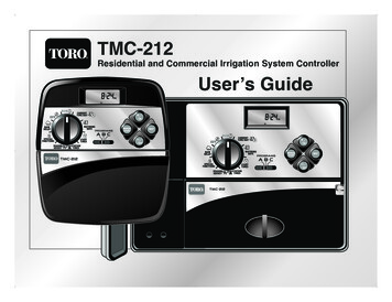
Transcription
373-0402 TMC-212 UG-E:373-0319 TCM 212 Doc2 8/5/08 10:06 AM Page aTMC-212Residential and Commercial Irrigation System ControllerUser’s Guide
373-0402 TMC-212 UG-E:373-0319 TCM 212 Doc2 8/5/08 10:06 AM Page bCongratulations! You have chosen one of the mostsophisticated and technologically advanced irrigationsystem controllers available for residential andlight-commercial applications.Your new Toro TMC-212 controller features:Flexible Station Count from 2 to 12 Stations with2-station Expansion modules:Standard and High-surge Expansion ModulesLocking Outdoor CabinetAutomatic Pump Start/Master Valve Control Circuit365-day Calendar3 Fully-independent Watering Programs Featuring:4 Start Times3 Watering Day Schedule Options:7-day Calendar7-day Interval with Day ExclusionOdd/Even Days with Day ExclusionStation Time from 1 Minute to 4 HoursPump Start/Master Valve Timing ControlWell Recovery/Station Delay TimeSeason Adjust from 10 to 200 %Rain Delay from 1—7 DaysAutomatic Program/Start Time StackingRain Sensor Ready:Compatible with All Rain Sensor TypesSensor Circuit Bypass SwitchRemote Control ReadyAutomatic Circuit Protection—Eliminates FuseNon-volatile Program Memory—Eliminates BatteryThe TMC-212 controller features several unique andhelpful operating characteristics. To take advantage ofthese features, spend just a few minutes to browsethrough this manual to familiarize yourself with your newcontroller.This booklet is divided into six main sections: The first section provides a brief description ofthe controller components and display elements. The second section takes you step-by-step throughthe installation process. The next section provides fundamental irrigationsystem operation, basic controller operation as wellas specific programming and operating characteristicsof the TMC-212. The fourth section takes you step-by-step through theprogramming process. The fifth section explains the various methods of automatic and manual controller operations. Finally, an appendix provides helpful reference information, troubleshooting, specifications and warrantyinformation.A convenient watering schedule form (affixed to thecover of the outdoor model controller and included onpage 20) enables you to record and keep specific stationand watering program information on hand with yourcontroller.The Quick Reference Guide provided with your UserGuide should also be kept with your controller. Thebooklet fits conveniently between the cabinet back andthe mounting bracket of the Indoor model. For Outdoormodel controllers, hang the booklet on the hook providedinside the cabinet cover.
373-0402 TMC-212 UG-E:373-0319 TCM 212 Doc2 8/5/08 10:06 AM Page 1Table of ContentsController Components.2 Controller Installation Indoor Model Installation .6 Connecting the Valves .7 Connecting a Pump Start Relay.8 Connecting the Transformer .8Outdoor Model Installation .9 Preparing the Cabinet for Installation.9 Installing the Cabinet.10 Connecting the Valves .11 Connecting a Pump Start Relay.12 Connecting the Power Source .13Connecting a Rain Sensor.13 Controller Operations Getting Started Irrigation System Basics .14Watering Program Basics .15Watering Program Details.16Planning Your Watering Schedule.18Filling Out the Watering Schedule Form.18 Watering Schedule Form .20Programming the Controller About the Controller Memory.21Setting the Current Time and Day or Date .21Setting the Watering Day Schedule.22 Setting a Calendar Schedule .22 Setting an Interval Schedule .23 Setting an Odd or Even Schedule.24 Using the Day Exclusion Feature .25Turning Off a Program .26Setting Program Start Times .27Setting Station Times.28Setting Pump/Master Valve andWell Recovery Controls .28 Automatic Mode .30Manual Mode .31 Operate Watering Program(s).31 Operate Stations .31 Watering Control Features .32 Pause Watering .32 Resume Watering .32 Cancel Watering .32 Skip Stations .32 Adjust the Station TIme During Operation .33Rain Delay Feature.33Season Adjust Feature .34Turn Off Operation.35Appendix Clearing the Program Memory.36About Automatic Circuit Protection .37Adding a 2-Station Expansion Module.37Using Pump/Master Valve Controls.38Troubleshooting .40Specifications.41Warranty .42Electromagnetic Compatibility .421
373-0402 TMC-212 UG-E:373-0319 TCM 212 Doc2 8/5/08 10:06 AM Page 2Controller ComponentsController Components2
373-0402 TMC-212 UG-E:373-0319 TCM 212 Doc2 8/5/08 10:06 AM Page 3Controller ComponentsThe following are brief descriptions of the controllercomponents and display elements. Each of these itemswill be explained in further detail within the appropriateprogramming, operating and installation sections of thisguide.1 - LCD DisplayA - “Start Time” symbol is displayed when setting theprogram start times.B - “Well Recovery” symbol is displayed when wellrecovery time delay is in use.C - Program start time identification numbers 1–4.D - Main display of various time values and prompts.E - Program A, B and C identifiers.F - “Watering On” symbol is displayed when a watering station is running. Symbol blinks when wateringis paused.G - “Watering Off” symbol is displayed when RainDelay feature is active.H - “Percent” symbol is displayed when the SeasonAdjust feature is in use.I - Watering Station identification numbers.J - Day of the week identifiers.K - “Run Time” symbol is displayed when setting thewatering station run times.2 - Control Buttons /ON button – Increases the time display, scrollsforward through the program information and selectswatering days.–/OFF button – Decreases the time display, scrollsbackward through the program information andremoves watering days.button – Advances to the next portion of programinformation. Resumes watering if paused. Advancesthrough stations manually when watering.NEXTMANUAL START button – Selects and starts manualwatering operations.3 - Control Dial – Selects all controller programmingand operation controls (except Manual Start).Control Dial PositionsRUN– The normal dial position for all automaticand manual operations.CURRENT TIME/DAY– Enables the clock time andday to be set.WATERING DAYS– Enables the watering dayschedules to be set and reviewed.START TIMES– Enables the program start timesto be set and reviewed.STATION TIMES– Enables the station run time to beset and reviewed.(COnTInUED)3
373-0402 TMC-212 UG-E:373-0319 TCM 212 Doc2 8/5/08 10:06 AM Page 4Controller Components4SEASON ADJUST– Enables the station time ofall stations in a program to be simultaneouslyincreased or decreased in 10% increments.SPECIAL FUNCTIONS– Provides optional controland timing features for pump operation and wellrecovery delay feature.RAIN DELAY– Enables all watering operationsto be delayed from 1 to 7 days.OFF– Shuts off and prevents all automatic andmanual watering activity.4 - Program Select Switch – Three-position slideswitch used to select watering program A, B or Cduring the programming procedures and manualoperation.5 - Rain Sensor Circuit Control Switch – Enables theRain Sensor circuit to be bypassed as necessary.6 - Rain Sensor Configuration Switch – Configuresthe controller for operation with a normally-openor a normally-closed rain sensor.7 - Rain Sensor Connection Terminals – Snap-in wireconnectors for direct connection of a Rain Sensor.8 - Valve Common Connection Terminal – Snap-inwire connector for the valve common wire.9 - Pump/Master Valve Connection Terminal –Snap-in wire connector for connection of a pumpstart relay or master valve 24 VAC power wire.10 - Transformer Connection Terminals – Snap-inconnectors for transformer wires.11 - Two-station Expansion Module (Standard andHigh-surge Protection Models) – Each expansionmodule provides a snap-in wire connection for twostations. Up to six modules can be installed to expandthe TMC-212 control from 2 to12 stations. Standardsurge expansion module TSM-02 provides 1.3 Kvsurge protection per station and is identified by asingle lightning bolt symbol and black color.High-surge protection module TSM-02-H provides 6.0Kv surge protection per station and is identified by twolightning bolts, beige color and extended length.While both types of expansion modules are interchangeable with all TMC-212 models, the TSM-02-Hmodule can only provide 6.0 Kv surge protection wheninstalled in specially-equipped controller modelsTMC-212-ODH and TMC-212-ODH-50H.12 - Remote Control Receiver Jack – Modular jackprovided for the connection of the optional ToroEZ-RemoteTM remote control receiver cable.(Installation and operating instructions are providedwith the EZ-Remote control system.)13 - External Transformer – A Plug-in transformersupplies 24 VAC power to the indoor modelcontroller.14 - Internal Transformer – A built-in transformer supplies 24 VAC power to the outdoor model controller.15 - Input Power Terminal Block – Connectionterminals for AC power wires.
373-0402 TMC-212 UG-E:373-0319 TCM 212 Doc2 8/5/08 10:06 AM Page 5Controller Components456785
373-0402 TMC-212 UG-E:373-0319 TCM 212 Doc2 8/5/08 10:06 AM Page 6Controller InstallationIMPORTANT: TMC-212 indoor model is notweather resistant and must be installed indoors or ina protected location.Indoor Model Installation1. Select a location for the controller within 4' (1.2 m) ofan electrical outlet to enable the transformer wires toeasily reach. Make sure the outlet is not controlled bya light switch.2. Remove the mounting bracket attached to the backof the controller housing by pulling the lower edge ofthe bracket away and downward from the controllerhousing.3. Place the mounting bracket (A) against the wallaligning the top edge at about eye level. Drive three1" (25 mm) wood screws (B) into the wall through thethree holes provided in the bracket.Note: If you are installing the bracket on drywall ormasonry, install screw anchors (C) to prevent screwsfrom loosening.4. Optional - Insert 3/4" (19 mm) PVC conduit (D) forvalve wiring into bracket sleeve (E).65. Align the slotted openings on the back of controllerhousing with the mounting bracket tabs. Slide thecontroller downward to engage the tabs.Note: After installation, store the Quick ReferenceGuide and the Watering Schedule Form in thepocket (F) behind the controller.
373-0402 TMC-212 UG-E:373-0319 TCM 212 Doc2 8/5/08 10:06 AM Page 7Connecting the ValvesNote: Using 14 to 18 AWG (2.5mm2 to 1mm2) irrigationcable is recommended. This cable is made specifically forautomatic irrigation systems and is available in severallengths and conductor count. Always use a cable that hasat least one wire for each valve and one wire for the valvecommon connection.1. Route the valve control wires between the valves andthe controller.2. Attach the white-color cable wire to one wire fromeach valve solenoid. (Either solenoid wire can beused for this connection.) This wire is referred to asthe valve common.3. Attach a separate cable wire to the remaining wirefrom each valve solenoid. Make a note of the wirecolor code used for each valve and the station itcontrols. You will need to have this information whenconnecting the wires to the controller.4. Secure all wire splices using twist-on wire connectors.To prevent corrosion and possible short circuits, usea grease cap or similar waterproofing method toinsulate each connection.5. Route the wire cable into the controller through thelarge opening in the base of the housing or throughPVC conduit if it is installed. Remove 1/2" (13mm)of insulation from the end of each wire.MasterValveValve CommonWireStationValvesNote: The station module has snap-in wire connectorsTo attach wires, simply raise the lever and insert thebare wire end into the small hole beneath the lever.Press the lever down to secure the wire. Pull lightly onthe wire to confirm that it is locked into the module.6. Referring to the Controller Components on page 5 andthe diagram above, secure the valve common wire tothe terminal labeled COM (8). Connect the individualstation valve wires to the appropriate station moduleterminals (11). Connect the master valve control wire(if applicable) to the terminal labeled PUMP/MV (9).Note: Connecting a master valve or pump start relayis optional and may not be required for your sprinklersystem.7
373-0402 TMC-212 UG-E:373-0319 TCM 212 Doc2 8/5/08 10:06 AM Page 8Connecting a Pump Start RelayCAUTION: Never connect an auxiliary pumpstarter directly to the controller. A 24 VAC relay,rated at 0.50A maximum current draw, must be usedto connect the controller to the pump starter circuit.1. Route a wire pair from the pump start relay into thecontroller housing.2. Connect one wire to the valve common COM (8).Connect the remaining wire to the PUMP/MV (9)as shown below.Connecting the Plug-in TransformerCAUTION: Do not plug the transformer into anelectrical outlet until all of the wiring procedures havebeen completed.1. Route the cable from the transformer (13) through thesmall opening provided in the base of the housing.Wrap the cable around and through the restraining postas shown below.2. Connect one transformer cable wire to each terminallabeled 24 VAC (10). The wires can be connected toeither terminal.Jumper Wire24 VAC Pump Start RelayValve Common WireCAUTION: If the pump does not have an automatic pressure control switch, prevent pump damagedue to “dead-heading,” by connecting a jumper wirefrom any unused station terminal to a station terminalwith a valve wire connected.8Note: Refer to “Pump Control and Well Recovery” sectionon page 28 for important pump circuit control information.Note: The display will begin flashing 12:00 a.m. Pressany button to stop the display from flashing.
373-0402 TMC-212 UG-E:373-0319 TCM 212 Doc2 8/5/08 10:06 AM Page 9Outdoor Model InstallationPreparing the Cabinet for Installation1. Remove the lower housing cover (A) by pullingoutward on the handle.2. Remove two phillips screws from the transformeraccess cover (B). Pull the cover outward from thebottom to remove.3. Three lower mounting holes (C) are provided. Thecenter hole is open and the outer holes are plugged.If you intend to use the outer holes for installation,carefully drill through the plugs with a 3/16" (5mm)drill bit.Four wiring access holes are provided in the cabinetbase as follows:(D) - 1/2" (13mm) for power and equipment ground wires.(E) - 1/2" (13mm) (plugged) for optional Toro RainSensor wires.(F) - 3/4" (19mm) for sprinkler valve wires.(G) - 1/2" (13mm) (plugged) for optional Toro remotecontrol cable.4. If planning to install the optional Toro components,remove the plugs as necessary.9
373-0402 TMC-212 UG-E:373-0319 TCM 212 Doc2 8/5/08 10:06 AM Page 10Installing the Cabinet1. For safe, reliable operation, select an installation sitewhich will provide the following conditions: Protection from irrigation spray, exposure to directsun during the hottest hours, wind and snow. Access to a grounded power source which is notcontrolled by a light switch or utilized by a highcurrent load appliance, such as a refrigerator or airconditioner. Access to the sprinkler control valve wiring andoptional accessory wiring.2. Drive a wood screw (provided) into the wall at eyelevel (A). Leave the screw extended approximately1/4" (6.5 mm) from the wall.Note: If you are installing the controller on drywallor masonry, install screw anchors to prevent screwsfrom loosening. Use the dimension shown to predrillholes for screw anchors.3. Hang the cabinet on the screw using the keyholeslot (B) on the back panel. Make sure the cabinetslides down securely on the screw.4. Install the lower mounting screw(s) and tightensecurely.Note: Conduit and adapters are not provided. Installconduit as required by local electrical codes.5. Install 1/2" (13 mm) conduit (C) for power/equipmentground wires and 3/4" (19 mm) conduit (D) for valvewires.10Note: After installation, store the User’s Guide andQuick Reference Guide on the hook located on theinside of the door.6" (15.24 cm)
373-0402 TMC-212 UG-E:373-0319 TCM 212 Doc2 8/5/08 10:06 AM Page 11Connecting the ValvesNote: Using 14 to 18 AWG (2.5mm2 to 1mm2) irrigationcable is recommended. This cable is made specifically forautomatic irrigation systems and is available in severallengths and conductor count. Always use a cable that hasat least one wire for each valve and one wire for the valvecommon connection.1. Route the wire cable from the valve location into thecontroller cabinet.11892. Attach the white (preferably) cable wire to either wirefrom each valve solenoid. This is called the valvecommon wire.Note: The solenoid does not have specific polarity,so either wire can be used for the common wireconnection.3. Connect an individual color-coded cable wire to theremaining solenoid wire of each valve. Make a notethe wire insulation color used for each connection andthe sprinkler zone controlled by the valve.IMPORTANT: To prevent possible short-circuitconditions causing controller damage, properlyconnect, insulate and waterproof all wire splices.4. Remove 1/2" (13mm) of insulation from the end of allcable wires to be connected to the controller.MasterValveValve Common WireStationValvesNote: The station module has snap-in wire connectors.To attach wires, simply raise the lever and insert the barewire end into the small hole beneath the lever. Press thelever down to secure the wire. Pull lightly on the wire toconfirm that it is locked into the module.5. Referring to the Controller Components on page 5 andthe diagram above, secure the valve common wire tothe terminal labeled COM (8). Connect the individualvalve wires to the appropriate expansion module terminals (11). The stations are numbered from left toright, 1 through 12. Connect the master valve wire(if applicable) to the terminal labeled PUMP/MV (9).11
373-0402 TMC-212 UG-E:373-0319 TCM 212 Doc2 8/5/08 10:06 AM Page 12Connecting a Pump Start RelayCAUTION: To prevent controller damage, neverconnect an auxiliary pump starter directly to thecontroller’s 24 VAC output. A 24 VAC 0.50A relay,must be used to connect the controller to the pumpstarter circuit.1. Route a wire pair from the pump relay into thecontroller housing.2. Connect one wire to the terminal labeled COM (8).Connect the remaining wire to the terminal labeledPUMP/MV (9) as shown below.Jumper WireConnecting the Power SourceWARNINGAC power wiring must be installed and connectedby qualified personnel only. All electrical components and installation procedures must complywith all applicable local and national electricalcodes. Some codes may require a means of disconnection from the AC power source installed in thefixed wiring and having a contact separation of atleast 0.120" (3mm) in the line and neutral poles.Make sure the power source is OFF prior to connecting the controller.1. Route the power and equipment ground wires fromthe power source, through the conduit and into thecontroller transformer compartment.Note: The controller terminal block accepts wire sizeup to 12 AWG (4 mm2).2. Remove 3/8" (10 mm) insulation from the wire ends.Pump Start RelayValve Common WireCAUTION: To prevent pump damage due toprolonged dead-head pressure, connect a jumper wirefrom an unused station terminal to a terminal with awith a valve connected.12Note: Refer to “Pump Control and Well Recovery” sectionon page 28 for important pump circuit control information.3. Using a small flat blade screwdriver, secure the wiresas shown to the terminal block as follows:Line or Line 1 (L1) to L, Neutral or Line 2 (L2) to Nand Equipment Ground to.4. Install and secure the transformer compartment cover.5. Apply power to the controller.Note: The display will begin flashing 12:00 a.m. Pressany button to stop the display from flashing.
373-0402 TMC-212 UG-E:373-0319 TCM 212 Doc2 8/5/08 10:06 AM Page 13Connecting the Power Source (cont.)Toro Rain SensorModel TWRS5PlasticInsert6Connecting a Rain Sensor (optional)A rain sensor is an optional control device that connectsdirectly to the TMC-212 to automatically interrupt automatic controller operation during rain.A sensor bypass switch is provided to enable sensoroperation to be disabled as needed.A sensor configuration switch enables the controller towork with a normally-open or normally-closed rain sensor.When the rain sensor absorbs moisture it signals theTMC-212 to suspend automatic watering operations.The no Watering symbol is displayed until the sensordrys out and automatically resets.When the no Watering symbol disappears, controlleroperation will resume as programmed.1. Route the sensor wires into the controller housingthrough the access hole provided.2. Release the Sensor terminal connectors and removethe plastic u-shaped insert. Connect the sensor wiresper the instructions provided with the sensor.3. Set the Sensor configuration switch (6) to NC(normally Closed) or NO (normally Open) as requiredby the sensor type installed.IMPORTANT: Do not use ENB and NC switchposition simultaneously unless a Normally Closedrain sensor is connected. Watering operation willbe suspended if this condition occurs.4. Set the Sensor control switch (5) as required: ENB(enable) allows the rain sensor to interrupt watering;DIS (disable) bypasses the rain sensor input.5. Refer to the instructions provided with the rain sensorfor complete setup and operating information.13
373-0402 TMC-212 UG-E:373-0319 TCM 212 Doc2 8/5/08 10:06 AM Page 14Getting Started –Irrigation System BasicsThe three major components of every automatic sprinklersystem are the controller, the control valves and thesprinklers/emitters.The controller is the brain of the system, signaling eachcontrol valve when and how long to open. The valves areconnected to expansion modules within the controller, andidentified as Station 1, Station 2, etc. Each station controlsa group of sprinklers in a specific portion of the landscapecalled a watering “Zone.” The zones are generally laid outaccording to the type of plant material being watered andthe type and flow rate of the sprinklers used to distributethe water.Automatic controller “Programs” are used to establishand organize different watering schedules. The TMC-212provides three independent watering programs, designatedA, B and C, and are established by specifying: what day(s)of the week to water – called watering days, what timeto start watering – called start time and how long eachstation runs – called station time.Each station can be assigned to each program and have adifferent amount of run time in each program.When an automatic program starts, each station with anassigned run time in the program will operate one by one innumeric sequence, from lowest to highest station number.ControllerValve 1Valve 2Valve 3HouseValve 4Valve 5Valve 1 - Station 1 - Parkway Lawn - Fixed SprayValve 2 - Station 2 - Front Lawn - Fixed SprayValve 3 - Station 3 - Front Shrubs - Flood BubblerValve 4 - Station 4 - Back Lawn - Geared RotorValve 5 - Station 5 - Garden - Drip14
373-0402 TMC-212 UG-E:373-0319 TCM 212 Doc2 8/5/08 10:06 AM Page 15Watering Program BasicsThe following example illustrates how a typical wateringprogram could be set up for the sprinkler system shownon the previous page.The diagram at the right depicts the watering program ina timeline format.Example: The program start time is set for 3:00 a.m.Lawn stations 1 and 2 each have a run time of 10 minutes and lawn station 4 is set to run for 20 minutes. notethat stations 3 and 5 water shrubs and flowers and havebeen excluded from this program. (These stations will beset to operate on a separate program).As shown in the watering program diagram, at 3:00 a.m.the controller starts the program watering cycle.Station 1 sprinklers run for 10 minutes and shut off. next,station 2 sprinklers turn on, run for 10 minutes and shutoff. The controller skips station 3, and turns on station 4which runs for 20 minutes and shuts off. Station 5 isskipped and the watering cycle ends at 3:40 a.m.As you can see from this example, only one programstart time was needed to operate three different stations.Using more than one program for example, would enablelawn zones to be watered every day on program A,shrub zones to run on on Monday, Wednesday andFriday on program B and drip irrigation to soak theflower beds every three days on program C.Note: Although the TMC-212 offers the multiple programfeature, you may want to use one program only if itmeets your needs. The remaining programs can beturned off and on as you need to use them.Watering Program DiagramProgram Startsat 3:00 a.m.Station 1Station time10 minutes1239612Station 2Station time10 minutes39612Station 4Station time20 minutesProgram Endsat 3:40 a.m.39615
373-0402 TMC-212 UG-E:373-0319 TCM 212 Doc2 8/5/08 10:06 AM Page 16Watering Program DetailsThis section covers in detail each of the three parts ofa watering program: watering days, program start timesand station times.Selecting a Watering Day ScheduleThe TMC-212 provides three optional formats to schedulewatering days: Calendar, Interval and Odd/Even.The Calendar FormatThe Calendar format is a recurring 7-day schedule thatbegins on Sunday and enables you to select specific daysof the week to water.This illustration shows how aCalendar schedule would bedisplayed when the control dial isposition.in the WATERING DAYSIn this example, program A has watering days set forMonday (MO), Wednesday (WE) and Friday (FR).The Interval FormatThe Interval format provides a periodic watering dayschedule ranging from 1 (everyday) to 7 (every-7th day)in one-day increments. For example, to water every thirdday, you would select a 3-day interval.Since the interval schedule is not tied to specific days ofthe week, you can determine when the interval schedulewill start by selecting the initial watering day.16For example, if you have selected a 3-day Interval andtoday is Sunday, you may choose to have today, Mondayor Tuesday be the first watering day of the interval. If youselect Monday, the next watering day will be Thursday.This illustration shows how anInterval schedule would be displayed.In this example, program B has a3-day Interval schedule set to beginon Monday.Odd or Even Day FormatThe Odd or Even day format enables you to select allodd- or all even-numbered days of the month to water.This illustration shows how an Oddday schedule for program A wouldbe displayed.Day Exclusion FeatureSince the Interval and Odd/Even watering day formatsare not tied to actual calendar days, the Day Exclusionfeature enables you to exclude specific days of the weekfrom the watering schedule. For example, due to waterconservation restrictions, watering is not permitted onMonday. Also, the lawn is mowed on Saturday, so Monday and Saturday will be excluded from the schedule.This example shows the daysexcluded (dE) are Monday andSaturday in watering program A.Program OffSelecting Off disables the program until needed and doesnot alter or erase any of its current settings.This illustration shows how a programwould be displayed if it is turned Off.In this example, program C is Off.
373-0402 TMC-212 UG-E:373-0319 TCM 212 Doc2 8/5/08 10:06 AM Page 17Setting Program Start TimesSetting the Station Run TimeA program start time is the time of day an automaticprogram watering cycle will start. The TMC-212 enableseach watering program (A, B and C) to have four independent start times.Please note the following start time conditions: A watering program requires only one start time tooperate automatically. A start time is assigned to a watering program, not toan individual station. When a start time occurs, the stations with operatingtime assigned in the program will be operated one at atime (for their set duration) in numeric sequence. If a program start time occurs while the controller isalready running a watering cycle, the start will bedelayed until the current watering cycle concludes(known as “Stacking”).Station run time is the length of time a station valve staysopen during a watering cycle. Station run time can be setfrom 1 minute to 4 hours (in 1-minute increments).Program start times are indicated by numbers 1–4shown at the top of the display when the control dial is inthe START TIME position. Start time number 1 and itscorresponding start time (or OFF) will begin flashing.In this example, program A hastwo assigned start times. Starttime 1 is set for 1:00 a.m. andstart time 2 is set for 5 a.m.Start times 3 and 4 are currentlynot used. Only start time numbers with an assigned start timewill be displayed.FlashingWhen setting a station run time,
Congratulations! You have chosen one of the most sophisticated and technologically advanced irrigation system controllers available for residential and
