Transcription
GeneralProductInformationWorkingSafelyAppendix AAdditional InformationESR-1844 &2290 ReportAppendix/GlossaryHardiePanel Vertical SidingHardieShingle SidingHardiePlank Lap SidingHardieSoffit PanelsHardieTrim HardieWrap Boards/Battens Weather BarrierFinishing stallationRequirementsTools forCutting andFasteningRAINSCREENS116Note: James Hardie has a capillary break requirementwhen installing HardiePanel on a Multi-Family/Commercial project. Please visitJamesHardieCommercial.com for further information.The Optional Use of Rain Screen Systems:James Hardie will support the use of its exterior sidingproducts with rainscreen systems, but does not takesole responsibility for the entire wall assembly or system.James Hardie expects the designer or builder using ourcomponents as part of the rainscreen system to: Adhere to all the installation requirements listed in therelevant product installation instructions. Provide adequate details for water management. Make the decision about the use of rainscreen. James Hardie products does not recommend “drainagemats” or “drainage boards” to provide the necessarycapillary break behind our siding. These products cancompress during the installation process, impairingthe drainage channels and further causing a “wavy”appearance in the plank or panel products. Understand the interaction between systemcomponents and how each of the components in thesystem interacts. Design of the building envelope accounting for bothinterior and exterior moisture control.Installation Over Furring:When installing James Hardie Siding products over furringthe question arises what thickness of furring can be usedas an alternate to normal metal or wood studs specified inthe ESR 1844 & 2290 Report. General rule of thumb is, thespecific ESR 1844 & 2290 fastener must be installed intoa material that has the same or better holding power thanthat specified in the ESR 1844 & 2290 and with the samepenetration as the ESR 1844 & 2290 fastener.Note: The ESR 1844 & 2290 is the primary code compliance documentJames Hardie utilizes, but for other common applications and/orproducts, additional code compliance documentation and/or fastenerspecifications may exist. For special circumstances out side the scope ofthe ESR 1844 & 2290, please contact James Hardie’s Technical Services.When reviewing the following details for attaching to woodfurring or framing, an important consideration is that thefastener chosen must be fully encompassed by a woodsubstrate - the furring may count as all or part of thenecessary penetration if it has been proven that the furringand/or wood substrate has the same or better holdingpower as a timber stud.Design responsibilityIn all cases it is the sole responsibility of the architect,envelope engineer or specifier to identify moisture relatedrisks associated with any particular building design andto make any appropriate adjustments or modifications tothe installation guidelines given by manufacturers. Wallconstruction and design must effectively manage moisture,considering both the interior and exterior environment ofthe building.Attaching lap siding to wood furring:When attaching lap siding products over wood furring,the typical fastener used is the 1-1/4 in. long No. 11 ga.roofing nail, blind nailed. This fastener is going to be theshortest fastener approved for fastening lap siding products,therefore the furring must be a minimum of 0.75 in. thick toachieve the same values as ESR 2290 Table 4 states for the11 ga. 1-1/4 in. roofing nail given plank reveal, stud spacing,building height and exposure category.A.1A.2Attaching lap siding to steel furring:When attaching lap siding products to metal furring, thesteel furring must be a minimum 20 gauge steel. A fastenershould be chosen out of the ESR 2290, Table 4, which isapproved for attaching to steel framing. Two general rulesthat should be considered when choosing a fastener is thata nail (pin) must penetrate steel furring ¼ in., and screwsmust penetrate steel furring 3 full threads. Therefore, if therules for steel fastening are followed – given plank reveal,stud spacing, building height, and exposure category – thevalues are the same as ESR 2290, Table 4 states for thechosen fastener.A.3A.4
GeneralProductInformationAdditional Information (continued)RAIN SCREENSA.6A.5A.7A.8Finishing andMaintenanceHardieWrap HardieTrim Weather Barrier Boards/BattensWhen attaching panel siding products to metal furring, the steelfurring must be a minimum 20 gauge steel. A fastener should bechosen out of the ESR 1844, Table 4, which is approved forattaching to steel framing. Two general rules that should beconsidered when choosing a fastener is that a nail (pin) mustpenetrate steel furring ¼ in., and screws must penetrate steel furring3 full threads. Therefore, if the rules for steel fastening are followed– given stud spacing, building height, and exposure category – thevalues are the same as ESR 1844, Table 4 states for the g panel siding to steel furring:Conditions of use: This practice is acceptable for transverse load only. This practice is not acceptable for racking shear values orin-plane forces other than perpendicular/normal wind forces. All vertical joints shall occur over framing. All other James Hardie Installation Requirements shall befollowed.GeneralInstallationRequirementsIt is deemed an acceptable practice to not fasten along the topand bottom plates for the 5/16 in. HardiePanel configurationslisted in the ESR 1844, Table 4 using the following fastener type: 0.091 in. shank X 0.225 in. HD X 1.5 in. long ring shank nail Min. No. 8 X 0.311 HD X 1 in. ribbed bugle head screw 0.10 X 0.25 in. HD X 1.5 in. long ET&F pin or equivalent 6d common 2 in. long nailTools forCutting andFasteningWhen attaching panel siding products over wood furring, thetypical fastener used is the 6d common 2 in. long nail.This fastener is going to be the shortest fastener approved forfastening panel siding products into wood, therefore the furringmust be a minimum of 1-11/16 in. thick to achieve the samevalues as ESR 1844, Table 4, given stud spacing, building height,and exposure category.WorkingSafelyAttaching panel siding to wood furring:HardieSoffit PanelsHardiePlank Lap SidingHardieShingle SidingHardiePanel Vertical SidingAppendix/GlossaryESR-1844 &2290 Report117
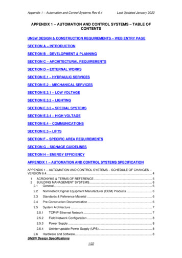
GeneralProductInformationAdditional Information (continued)ESR-1844 &2290 ReportAppendix/GlossaryHardiePanel Vertical SidingHardieShingle SidingHardiePlank Lap SidingHardieSoffit PanelsHardieTrim HardieWrap Boards/Battens Weather BarrierFinishing stallationRequirementsTools forCutting andFasteningWorkingSafelyAttaching James Hardie Products to Insulated Concrete Forms (ICF)118Considering the proprietary nature of Insulated Concrete Forms (ICF) and the number of ICF manufacturers currentlyselling product in the US and Canada, James Hardie Building Products cannot calculate or determine the properfastener for each type of plastic or metal cross-tie flange being used in the field. James Hardie offers the following asa guide to determine the correct siding fastening to be used with the respective ICF system chosen for the project inquestion.1. Determine the projects basic wind design, including basic wind speed, wind exposure category, and mean roof height.Find the fastener and frame type within James Hardie’s ICC-ES Product Evaluation Report (e.g. ESR 1844 & 2290)that will meet the project’s basic wind design.Take note of the head diameter, shank diameter, and fastener length for the fastener.HeaddiameterShankdiameterNote: Fastener bearing area is equal tothe head area less the shank area.LengthTake note of the frame type and frame spacing.Go to the ICF system manufacturer and find a fastener that is similar in dimension to the fastener from step 2.1 above.Basically, the bearing area under the ICF fastener head shall be the same as or greater than the bearing areaunder the James Hardie fastener head from step 2.Since the James Hardie siding product has to be attached to a structural member, in this case the ICF cross-tieflange, the steps below shall be followed.The onus is on the ICF system manufacturer to demonstrate that their ICF cross-tie flange holds fasteners,screws or nails, the same as wood or steel framing hold screws or nails.ICF fastener allowable withdrawal load capacity (applicable factor of safety applied) may be found in an ICC-ESProduct Evaluation for the given ICF manufacturer’s products, ORThe ICF manufacturer may have testing that shows their fastener’s allowable withdrawal load capacity(applicable factor of safety applied) from their cross-tie flange.For the fastener from step 2, a registered design professional shall calculate the allowable withdrawal load (factor ofsafety applied) from the frame type noted in step 2.2.A registered design professional shall then make an equivalency statement comparing the ICF fastener withdrawal(step 4.1.1 or step 4.1.2) versus the fastener withdrawal from step 5.When the ICF cross-tie flange spacing differs from the James Hardie frame spacing in step 2.2, a registered designprofessional shall calculate the maximum siding fastener spacing into the cross-tie flange needed to resist theapplicable basic wind speeds published inA.9ConcreteJames Hardie’s ESR 1844 & 2290 for thefastener and design from step 2.InsulatingWhen required by the code official and onceFoamin possession of the information gathered inNailing Flangethe steps above it is the responsibility of theReinforcementproperty owner, design professional,contractor, or installer to make his or hercase to the Building Official¹.¹ The Building Official reserves the right to approve alternate materials, designand methods of construction, 2006 International Building Code Section 104.11,2006 International Residential Code Section R104.11, and 1997 Uniform BuildingCode Section 104.2.8.Starter strip buildsout siding to theproper angleJointflashingInstall factoryends of planksat butt jointsRefer to ICF Manufacturer for compliant fastening
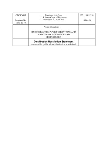
GeneralProductInformationCMUwallFurring strip toaccommodate sidingfastener lengthMasonry fastenerStarter strip(same as HardiePlankplank)lap siding TrimBlind nailingsiding fastener6” clearanceto grade Trim6” clearanceto gradeHardiePanel Vertical SidingStarter strip(same asplank) HardiePlanklap sidingHardiePlank lap sidingHardieShingle SidingCMU wallMasonrysiding nailHardiePlank Lap SidingA.13A.12HardieSoffit PanelsMethod 2: Attachment Directly to CMUAttach directly to masonry with approved fastening method according to local building codes and code compliancedocumentation.Refer to and follow local building codes for water resistive barrier requirementsHardieWrap HardieTrim Weather Barrier Boards/BattensFurring strips toaccommodatesiding fastenerlengthBlind nailingsiding fastenerFinishing andMaintenanceA.11Spacedmaximum24” tionRequirementsMethod 1: Attachment Over FurringAttach over furring with adequate thickness to allow attachment with approved fastening methods according to localbuilding codes and code compliance documentation. Furring must be attached to ensure it can transfer the windloads and other necessary forces back to the structure. The mechanical connection of the furring to the structure isthe responsibility of the Licensed Design Professional. James Hardie Building Products has no comment on the loadcarrying capacity of the furring to framing connections.Tools forCutting andFasteningThe application of HardiePlank Lap Siding and HardieTrim boards to masonry construction complying with localbuilding codes using Concrete Masonry Units (CMU) complying to ASTM C 90 can be achieved by using one of thefollowing two methods of attachment. All other product specific installation requirements which are not outlined belowmust be followed.WorkingSafelyATTACHING HARDIEPLANK LAP SIDING AND HARDIETRIM PRODUCTSTO CONCRETE MASONRY UNITS (CMU)Appendix/GlossaryHardieTrim boards can be fastened using hardened finish nails designed for masonry construction. For moreinformation refer to the HardieTrim section of this guide.ESR-1844 &2290 ReportAttachment of HardieTrim boards119
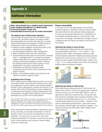
GeneralProductInformationAdditional Information (continued)ESR-1844 &2290 ReportAppendix/GlossaryHardiePanel Vertical SidingHardieShingle SidingHardiePlank Lap SidingHardieSoffit PanelsHardieTrim HardieWrap Boards/Battens Weather BarrierFinishing stallationRequirementsTools forCutting andFasteningWorkingSafelyICC – IBC & IRC /2006 – Allowable Fastener Spacing (in.)120HardiePlank Lap Siding fastened to ASTM C 90 Concrete WallBasic Wind Building 6½-inch wideSpeedHeight (feet)Exposure7¼- & 7½-inch wide8- & 8¼-inch wideExposureExposure9¼- & 9½-inch wideExposureBC100 20191817D191817161515110 51514131212120 31212111110130 11110999140 150 11099899888712121211111010109888887777Notes to Table:1. Fasteners shall be ET&F Fastening Systems, Inc. ET&F block Nail (ET & F No. ASM-144-125, head dia. 0.30 in., shank dia. 0.14 in., length 1.25-in. long) orMax System block Nail (CP-C 832 W7-ICC, head dia. 0.30 in., shank dia. 0.15 in., length 1.3 in.).2. Maximum basic wind speed shall be 150 mph.3. Interpolation to address building height and other plank widths is permitted.4. The lap conceals the fasteners of the previous course (Blind Nailed).5. 1 inch 25.4 mm, 1 foot 305 mm, 1 mph 0.44 m/s
GeneralProductInformationInstalling over Rigid foam insulation up to 1 thickWorkingSafelyJames Hardie does support the use of its exteriorsiding products installed over rigid foam insulation,but does not take responsibility for the entire wallassembly or system. James Hardie expects thedesigner or builder using our components as part ofthe insulated wall assembly to:A.14FlashingGeneralFastenerRequirements Adhere to all the installation requirements listed inthe relevant product installation instructions. Provide adequate details for water management. Make the decision about the use and type of rigidfoam insulation. Understand the interaction between systemcomponents and how each of the components in the system interacts. Design the building envelope to account for both interior and exterior moisture control.8-18 x 15/8 in. x .323 in. HD ribbedbugle head screw8-18 x 21/8 in. x .323 in. HD ribbedbugle head screwESR-1844 &2290 ReportRefer to the ESR-1844 & 2290 or other code compliant documentation for proper fastenerselection based on specific product, stud spacing, building height, and exposure category.Appendix/Glossary11 ga. 1¾ in. long roofing nailHardiePanel Vertical Siding11 ga. 1¼ in. long roofing nailHardieShingle Siding8d common 2½ in. longHardiePlank Lap Siding6d common 2 in. longHardieSoffit PanelsFastener for an additional 1/2 in. of FoamHardieWrap HardieTrim Weather Barrier Boards/BattensNormal FastenerNails are driventhrough the sheathinginto the studs.Finishing andMaintenanceGeneral requirements and installation guidelines: All James Hardie product specific installation requirements must be followed. All national, state, and local building code requirements must be followed. Where they are more stringent than theJames Hardie installation requirements, state and local requirements will take precedence. James Hardie siding and trim products can be installed over solid-foam insulation board up to 1 inch thick. Cautionshould be taken as irregularities and unevenness in framing, sheathing, foam and other wall assembly components,including under driven nails, can telegraph through to the finished siding and trim. These irregularities should becorrected before the siding is installed.A.15Fasteners are hidden When reviewing the following details for attaching over foam,by the course above.an important consideration is that the fastener chosen must beadequately encompassed by a wood substrate. The foam will notcount as part of the necessary penetration, there for the length of thechosen fastener must be extended by the thickness of the foam.Fastener Selection: When attaching lap siding products over foam 1 or less, the length ofthe chosen fastener from table below, must be extended in length bythe thickness of the foam. For information on fastening Hardie productsgreater than 1 in. see Tech Bulletin 19 at sWater-resistive barrierJames Hardie sidingTools forCutting andFasteningRigid insulation121
GeneralProductInformationAdditional Information (continued)Note: When attaching lapsiding products over foamthe length of the chosenfastener must be extendedby the thickness of the foamto achieve the same requiredholding power.Tools forCutting andFasteningWorkingSafelyA.16ESR-1844 &2290 ReportAppendix/GlossaryHardiePanel Vertical SidingHardieShingle SidingHardiePlank Lap SidingHardieSoffit PanelsHardieTrim HardieWrap Boards/Battens Weather BarrierFinishing stallationRequirementsTIP: With some typesof foam it is possible touse the rigid foam as thewater resistive barrier bytaping and sealing all ofthe joints. Refer to specificmanufacturers installationrequirements whenconsidering this type ofapplication.122Weather barrier & Rigid foam When using a weather resistive barrier (WRB) in conjunction with rigid foaminsulation, the WRB can be installed underneath the foam as shown, orover the top if more convenient Regardless of where the WRB is placed all flashings must beincorporated into the WRB and drainage plane. Some rigid foam insulation products are manufactured with tongue &groove or shiplap joints and can be used as the WRB when properlyinstalled and sealed. When using rigid foam insulation as the WRB referto manufacturers installation instructions.TrimDepending upon the reveal around windows, doors, & penetrations,thickness of foam and the type and thickness of trim used there will bedifferent techniques to install the siding and trim to ensure the foam iscompletely concealed.A.17water-resistive barrierrigid insulationjoint flashing1/8 in. caulked gap isleft between siding andthe side trim piecesPre-built corner using a pair ofnails (one in each face) attachthe corner to the buildingFlashingsThe Z flashing above all horizontal trim must be incorporated into the WRB regardless of WRB position. If the foam isbeing used per manufacturers instructions as the WRB, all flashings must be incorporated into the drainage plane suchthat it allows moisture to drain down and out.A.18Water-resistive barrierStructuralSheathingStarter StripDon’t caulk gapbetween flashing andupper panel.Rigid InsulationFlashing1/4 in. Gap1/8 in. caulked gap isleft between siding andthe side trim piecesTrim to be added tokeep window proudof siding when addingrigid insulationNote: It is recommended tolayout the rigid foam insulationsuch that vertical joints do notoccur at the corners of windowand door openings or overs ifpossible.
GeneralProductInformationInstalling Hardieplank Lap Siding Around Windows with an Integrated J-ChannelWorkingSafelyWhen installing fiber cement around a window with a “J” channel there are a fewguidelines which should be followed to control water flow:Typical “J” Channel Window Hardie Wrap TapeHardie WeatherResistiveBarrierSeamTapeOption 2J Channelof WindowPieces ofFlashingWeatherResistive BarrierSeal field cut endsDo not caulkAppendix/GlossaryESR-1844 &2290 ReportJames Hardie recommends 6-in. wide flashing that overlaps the course below by 1 in. Some local building codesmay require different size flashing. Joint-flashing material must be durable, waterproof materials that do notreact with cement products. Examples of suitable material include finished coil stock and code compliant waterresistive barriers. Other products may also be suitable.HardiePanel Vertical SidingOne or more of the following joint treatment options are required by code (as referenced 2009 IRC R703.3.2)A. Joint Flashing (James Hardie recommended)B. Caulking* (Caulking is not recommended for ColorPlus for aesthetic reasons as the Caulking and ColorPluswill weather differently. For the same reason, do not caulk nail heads on ColorPlus products.}C. “H” jointer cover Flashing behind butt joints provides an extra level of protection against the entry of waterat the joint.HardieShingle SidingJoint flashing with Hardieplank lap sidingHardiePlank Lap SidingOption 1FlashingHardieSoffit PanelsOne piece ofFlashingHardieWrap HardieTrim Weather Barrier Boards/BattensZ Flashing (Refer to James HardieInstallation Instructions)Weather Resistive BarrierFinishing andMaintenanceWrap TapeGeneralFastenerRequirementsA.20Weather Resistive BarrierGeneralInstallationRequirementsA.19Tools forCutting andFastening1. All windows must be installed per manufacturers installation instructions and mustincorporate all necessary flashings.2. At the bottom sides of the window, a flashing must be installed that will redirect anywater that runs down the inside of the “J” channel out and away so that it does not rundown the wall assembly and behind the plank below the window.a. This can be done by inserting a flashing that runs the entire length of the window(option 1) or by cutting the weather resistive barrier towards the bottom of thewindow and inserting a smaller flashing and taping with seam tape to reseal theweather resistive barrier (option 2).b. This flashing would then be lapped over the last plank at the bottom of thewindow, similar to a joint flashing, to direct water down and out to the front of thecladding.3. A “z” flashing must be installed and integrated into the weather resistive barrier atthe top of the window. The “z” flashing will allow water to be drained away from thewindow and wall, opposed to being captured in the “J” at the top of the window.(Refer to James Hardie Installation Instructions for further “z” flashing details).4. Seal all field cut non factory ends with an exterior grade paint, primer, or sealer.a. Insert ends of plank into the “J” channel of the window.b. Do not try to squeeze caulk into the “J” channel.c. Plank integrated into “J” channel must be primed, painted or caulked.123
GeneralProductInformationWorkingSafelyTools forCutting FastenerRequirementsFinishing andMaintenanceThe reasons for this are:1. The use of joint flashing behind field butt joints is an approved joint treatmentmethod as described in the 2006 International Building Code and is recognized byJames Hardie and experts across the building industry to be a superior method.“1405.17.2 Horizontal lap siding. Lap siding shall be lapped a minimum of 11/4 inches (32 mm) and shall have the ends sealed with caulking, covered withan Hsection joint cover or located over a strip of flashing.”Joint flashingA.21Experts across the industry recognize flashings as an effective and responsiblemethod for draining a wall system:“The fundamental principle of water management is to shed water by layeringmaterials in such a way that water is directed downwards and outwards out of thebuilding or away from the building. The key to this fundamental principle is drainage.The most elegant expression of this concept is a flashing. Flashings are the mostunder-rated building enclosure component and arguably the most important.”EEBA (Energy & Environmental Building Association ) Water ManagementGuide By Joseph W. Lstriburek, Ph.D., P.eng. June 2004.A.222. Reduced maintenance required by the home owner – It is recognized by James Hardie,several caulking manufacturers, experts across the industry, and experienced homeowners that when caulking is used at field butt joints, maintenance will be required.Depending on the specific product and the application, caulked field butt joints willneed to be maintained to guarantee continued performance over the life of the building.In addition, several sealant/caulking manufacturers recommend against using theirproducts at butt joints in fiber cement siding for many of the reasons discussed here.3. Improved appearance – When installed properly, flashing at a field butt joint can create abetter looking joint. James Hardie recommends butting field joints together in moderatecontact which achieves a more continuous looking joint. When utilizing a caulked buttjoint, a gap specified by the caulk manufacturer must be left at the joint. Over time asthe caulk ages, this joint can become pronounced on the wall and stand out.ESR-1844 &2290 ReportAppendix/GlossaryHardiePanel Vertical SidingHardieShingle SidingHardiePlank Lap SidingHardieSoffit PanelsHardieTrim HardieWrap Boards/Battens Weather BarrierAdditional Information (continued)124Do not use caulk on HardiePlank lapsiding with ColorPlus technologyJames Hardie Requirements for Alternate Fasteners and Methods of FasteningThe fastening requirements for each product are stated in one or more of the following technical documents and insome cases fastener products may be referenced. Below are the steps that can be used to demonstrate an alternatefastener’s equivalency to the James Hardie published fastening requirements.1. It is the responsibility of either the property owner, design professional, contractor, or installer to consult:a. The fastener Manufacturer for a Product Listing Specification or Code Compliance report that covers theinstallation method in question, or;b. A licensed Architect or Professional Engineer to make an equivalency statement linking the alternatefastener (or fastening method) to the fastening requirements published within the relevant James Hardietechnical document;2. Once in possession of the information gathered in step one it is the responsibility of the property owner, designprofessional, contractor, or installer to make his or her case to the Building Official¹¹ The Building Official reserves the right to approve alternate materials, design and methods of construction, 2006 International Building Code Section 104.11, 2006 International Residential Code Section R104.11, and 1997 Uniform Building Code Section 104.2.8.All national, state, and local building code requirements must be followed and where they are more stringent than the James Hardie installationrequirements, state and local requirements will take precedence.
GeneralProductInformationAppendix BWorkingSafelyEstimatingSidingB.1Wall AreaTools forCutting andFasteningAll houses can be broken down to triangles, rectangles, and squares.Using these simple shapes it is very easy to estimate the amount ofsiding required.Height2. Determine the height and width of each shape.B.24. Add all of the square footage numbers together.5. Subtract large items such as garage doors, large doors, largewindows, and banks of windows from total.Do not remove small windows, doors, vents, or other small areasnot being sided.Gable AreaHeightFinishing andMaintenanceWidth7. Use the coverage charts located in this section to determine thenumber needed.1/2 height x width area of gable (square feet)B.38. Add a minimum of 5% for waste. If there are multiple (3 or more)gables, chases, bump outs, or dormers add 10%.*Gambrel Roof House* Material for starter strip is included in the calculation for waste.CBTrimTrim is applied to corners and around doors and windows. Trim is also usedfor fascia board, rake board, band board, frieze board and other details.HardieSoffit PanelsDNumber of HardieTrim Boards:AWidthB.42. Measure all openings to be trimmed including doors, windows,vent openings, corners (inside and outside), and other areas.Dormer AreaWidthHardieShingle SidingHeight3. Measure for fascia, rakes, and frieze imESR-1844 &2290 ReportCornerTrimFasciaAppendix/GlossaryDisclaimer: The estimation methods in this section are meant as a guide.James Hardie does not assume responsibility for over or under orderingof product.1/2 height x width area of dormer (square feet)HardiePanel Vertical Siding4. Add the lengths for corners, fascia, rakes, and frieze and add 5%for waste.5. Add the lengths for window and door trim and add 10% for waste.HardiePlank Lap Siding1/2 (A B) x C 1/2 B x D total area of gable(square feet)1. Determine which areas are to be trimmed.HardieWrap HardieTrim Weather Barrier Boards/Battens6. Total all numbers. This gives you the total covered area.6. Add the total from lines 4 and 5 to determine the amountof trim needed.GeneralFastenerRequirementsWidthHeight feet x width feet square feet3. Multiply height x width to determine square footage. For trianglesdivide the total by 2.GeneralInstallationRequirements1. Break down the portions of the house to be sided into the simpleshapes (squares, rectangles, triangles) Figures 12.1 - 12.4.125
GeneralProductInformationHardiePlank Lap Siding Coverage Chart*(number of planks)HardiePanel Vertical Siding Coverage Chart*(number of panels)Coverage Area(
James Hardie will support the use of its exterior siding products with rainscreen systems, but does not take sole responsibility for the entire wall assembly or system. James Hardie expects the designer or builder using our components as part of the rainscreen system to: Adhere to all the installation requirements listed in the