Transcription
Rainmaker HInstructions for use and parts listKent/Euroclean MODEL 5664998106/03 revised 11/03 Form Number 56041563
INTRODUCTIONThis manual will help you get the most from your Kent/Euroclean RainmakerTM H. Read thoroughlybefore operating the machine.NOTE: Bold numbers in parenthesis indicate an item illustrated on page 7.This product is intended for commercial use only.PARTS AND SERVICERepairs, when required, should be performed by your authorized Kent/Euroclean Service Center, whoemploys factory-trained service personnel, and maintains an inventory of Kent/Euroclean originalreplacement parts and accessories.Call the Kent/Euroclean DEALER named below for parts or service. Please specify the Model andSerial Number when discussing your machine.(Dealer, affix service sticker here)NAME PLATEThe Model and Serial Number of your machine are shown on the nameplate in the machine. Thisinformation is needed when ordering repair parts for the machine. Use the space below to note theModel and Serial Number of your machine for future reference.MODEL :SERIAL NUMBER :UNCRATINGWhen the machine is delivered, carefully inspect the shipping carton and the machine for damage. Ifdamage is evident, save the shipping carton so that it can be inspected. Contact Kent/EurocleanCustomer Service Department immediately to file a freight damage claim.DO NOT OPERATE THE MACHINE UNTIL YOU HAVE READ THIS SECTION.IMPROPER USE WILL VOID THE WARRANTY. Always use a defoamer when foaming occurs to prevent vacuum motor damage. Never use water above 140 F (60 C). Do not store outdoors. Avoid extremes in temperature. Do not let the pump run dry. Turn the pump off and refill that tank when cleaning solution gets low.Use approved chemicals only. All chemicals should be mixed thoroughly. Liquid chemicalsare recommended to prevent powder buildups. A pH between 6 and 9 is recommended.The use of high alkaline detergents or strong acids will accelerate the wear of the pumpand seals, and will void the warranty. All extension cords must have a rating of at least 12/3 (#12 cord). Extension cords shouldbe no longer than 50 feet. Replace the plug immediately if the ground prong becomesdamaged or is broken off.2 - FORM NO. 56041563 / Rainmaker H
IMPORTANT SAFETY INSTRUCTIONSThis machine is only suitable for commercial use, for example in hotels, schools, hospitals,factories, shops and offices other than normal residential housekeeping purposes.When using an electrical appliance, basic precautions should always be followed, includingthe following:Read all instructions before using this appliance.WARNING!To reduce the risk of fire, electric shock, or injury: Do not leave the appliance when it is plugged in. Unplug the unit from the outlet when not inuse and before servicing.To avoid electric shock, do not expose to rain. Store indoors.Do not allow to be used as a toy. Close attention is necessary when used near children.Use only as described in this manual. Use only the manufacturer’s recommended attachments.Do not use with damaged cord or plug. If the appliance is not working as it should be, hasbeen dropped, damaged, left outdoors or dropped into water, return it to a service center.Do not pull or carry by the cord, use the cord as a handle, close a door on the cord, or pull thecord around sharp edges or corners. Do not run the appliance over the cord. Keep the cordaway from heated surfaces.Do not unplug by pulling on the cord. To unplug, grasp the plug, not the cord.Do not handle the plug, cord or appliance with wet hands.Do not put any object into openings. Do not use with any opening blocked; keep free of dust,lint, hair, and anything that may reduce air flow.Keep loose clothing, hair, fingers, and all parts of body away from openings and moving parts.Do not pick up anything that is burning or smoking, such as cigarettes, matches, or hot ashes,or any health endangering dusts.Turn off all controls before unplugging.Use extra care when cleaning on stairs.Do not use to pick up flammable or combustible liquids such as gasoline or use in areaswhere they may be present.Connect to a properly grounded outlet only. See Grounding Instructions.Liquid ejected at the spray nozzle could be dangerous as a result of its temperature, pressureor chemical content.SAVE THESE INSTRUCTIONSFORM NO.56041563 / Rainmaker H - 3
CONSIGNES DE SECURITE IMPORTANTESCette machine ne convient qu à un usage industriel, par exemple dans des hôtels, écoles,hôpitaux, usines, boutiques et bureaux et autres à l exclusion de tout usage de maintenancerésidentielle normale.L’utilisation d’un appareil électrique demande certaines précautions:LIRE TOUTES LES INSTRUCTIONS AVANT DE FAIRE FONCTIONNER (CET APPAREIL)AVERTISSEMENT!Pour réduire les risques d’incendie, de choc électrique ou de blessure: Ne pas laisser l’appareil sans surveillance lorsqu’il est branché. Débrancher lorsque l’appareiln’est pas utilisé et avant l’entretien.Pour réduire les risques de choc électrique, utiliser à l’intérieur seulement.Ne pas permettre aux enfants de jouer avec l’appareil. Une attention particulière estnécessaire lorsque l’appareil est utilisé par des enfants ou à proximité de ces derniers.N’utiliser que conformément à cette notice avec les accessoires recommandés par le fabricant.Ne pas utiliser si le cordon ou la fiche est endommagé. Retourner l’appareil à un atelier deréparation s’il ne fonctionne pas bien, s’il est tombé ou s’il a été endommagé, oublié à l’extérieurou immergé.Ne pas tirer soulever ou traîner l’appareil par le cordon. Ne pas utiliser le cordon comme unepoignée, le coincer dans l’embrasure d’une porte ou l’appuyer contre des arêtes vives ou descoins. Ne pas faire rouler l’appareil sur le cordon. Garder le cordon à l’écart des surfaceschaudes.Ne pas débrancher en tirant sur le cordon. Tirer plutôt la fiche.Ne pas toucher la fiche ou l’appareil lorsque vos mains sont humides.N’insérer aucun objet dans les ouvertures. Ne pas utiliser l’appareil lorsqu’une ouverture estbloquée. S’assurer que de la poussière, de la peluche, des cheveux ou d’autres matières neréduisent pas le débit d’air.Maintenir les cheveux, les vêtements amples, les doigts et toutes les parties du corps à l’écart desouvertures et des pièces mobiles.Ne pas aspirer de matières en combustion ou qui dégagent de la fumée, comme des cigarettes,des allumettes ou des cendres chaudes.Mettre toutes les commandes à la position ARRÊT avant de débrancher l’appareil.User de prudence lors du nettoyage des escaliers.Ne pas aspirer des liquides inflammables or combustibles, comme de l’essence, et ne pas fairefonctionner dans des endroits ou peuvent se trouver de tels liquides.Ne brancher qu’à une prise de courant avec mise à la terre. Voir les instructions visant la mise àla terre.Le liquide qui sort de l’embout de vaporisation peut s’avérer dangereux en raison de satempérature, de sa pression ou du produit chimique qu’il contient.CONSERVER CES INSTRUCTIONS4 - FORM NO. 56041563 / Rainmaker H
120VAC GROUNDING INSTRUCTIONSThis appliance must be grounded. If it should electrically malfunction, grounding provides a path ofleast resistance for electric current to reduce the risk of electric shock. This appliance is equippedwith a cord having an equipment-grounding conductor and grounding plug. The plug must be pluggedinto an appropriate outlet that is properly installed and grounded in accordance with all local codesand ordinances.DANGER!Improper connection of the equipment-grounding conductor can result in a risk of electric shock.Check with a qualified electrician or service person if you are in doubt as to whether the outlet isproperly grounded. Do not modify the plug provided with the appliance. If it will not fit the outlet, havea proper outlet installed by a qualified electrician.This appliance is for use on a nominal 120-volt circuit, and has a grounding plug that looks like theplug illustrated in Figure 1 below. A temporary adapter illustrated in Figures 2 and 3 may be used toconnect this plug to a 2-pole receptacle as shown in Figure 2 if a properly grounded outlet is notavailable. The temporary adapter should be used only until a properly grounded outlet (Figure 1) canbe installed by a qualified electrician. The green-colored rigid ear, tab, or the like extending from theadapter must be connected to a permanent ground such as a properly grounded outlet box cover.Whenever the adapter is used, it must be held in place by a metal screw. Grounding adapters are notapproved for use in Canada.Replace the plug if the grounding pin is damaged or broken.The Green (or Green/Yellow) wire in the cord is the grounding wire. When replacing a plug, this wiremust be attached to the grounding pin only.Extension cords connected to this machine should be 12 gauge, three-wire cords with three-prongplugs and outlets. DO NOT use extension cords more than 50 feet (15 m) long.PLEASE NOTE: FOR NORTH AMERICA ONLYFORM NO.56041563 / Rainmaker H - 5
INSTRUCTIONS VISANT LA MISE À LA TERRE (120VAC)Cet appareil doit être mis à la terre. En cas de défaillance ou de panne éventuelles, la mise a la terrefournit au courant un chemin de moindre résistance qui réduit le risque de choc électrique. Cetappareil est pourvu d’un cordon muni d’un conducteur de terre et d’une fiche avec broche de terre.La fiche doit être branchée dans une prise appropriee correctement installée et mise à la terreconformément aux règlements et ordonnances municipaux.AVERTISSEMENT !Un conducteur de terre mal raccordé peut entraîner un risque de choc électrique. Consulter unélectricien ou un technicien d’entretien qualifié si vous n’êtes pas certain que la prise est correctementmise à la terre. Ne pas modifier la fiche fournie avec l’appareil - si elle ne peut être insérée dans laprise, faire installer une prise adéquate par un électricien qualifié.Cet appareil est destiné à un circuit de 120 V et est muni d’une fiche de terre semblable à celleillustrée par le croquis 1. Un adaptateur temporaire semblable à celui illustré par le croquis 2 et Cpeut être utilisé pour brancher cette fiche à une prise bipolaire comme l’illustre le croquis 2 si uneprise avec mise à la terre n’est pas disponible. L’adaptateur temporaire devrait etre utilisé seulementjusqu’à ce qu’une prise avec mise à la terre soit installée par un électricien qualifié. L’oreille rigide oule crochet ou autre dispositif semblable, de couleur verte, prolongeant l’adaptateur doit Iêtre raccordéà un élément correctement mis à la terre comme le couvercle d’une boîte de sortie mise à la terre.L’adaptateur doit être fixé par une vis métallique. Note: Au Canada, I’utilisation d’un adaptateurtemporaire n’est pas autorisée par le Code canadien de l’électricité.Remplacez la prise si la prise de terre est abîmée ou cassée.Le fil Vert (ou Vert/Jaune) dans la ganse est le fil de terre. Lors du remplacement d une prise, ce fildoit être raccordé à la prise de terre uniquement.Les ralonges connectées à cette machine doivent avoir 12 mesures, trois ganses de fil ayant troisfiches masculines féminines tree-prong plugs and outlets. N UTILISEZ PAS de ralonge de plus de15 m (50 pieds) de long.VEUILLEZ NOTER: CES INSTRUCTIONS CONCERNENT UNIQUEMENT L’AMÉRIQUE DUNORD6 - FORM NO. 56041563 / Rainmaker H
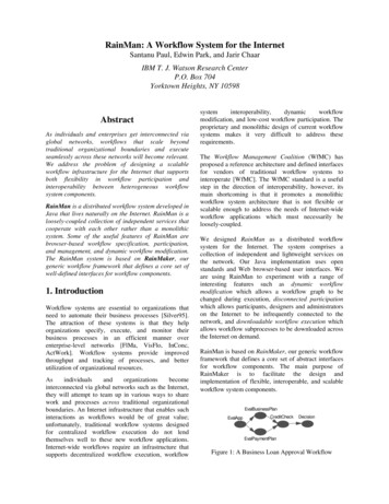
KNOW YOUR MACHINE153469287KNOW YOUR MACHINE DESCRIPTIONSOperator Handle (1) - Operator holds this to move the machine from one location to another.Lift Handle (2) - Operator grasps this handle when lifting the machine.Solution Tank Lid (3) - Fill Solution Tank here with warm water and chemicals.Recovery Tank Lid (4) - The Recovery Tank can be flushed out by running clean water into thisopening with the Recovery Tank Drain Hose open. The vacuum float Shut-OFF can also beaccessed through this opening for maintenance.Switch Plate (5) - The switches that operate the motors and the heater are located here, as wellas indicator lights for the heater.Vacuum Hose Connector (6) - This is where the vacuum hose attaches to the machine.Solution Hose Connector (7) - This is where the solution hose attaches to the machine.Latches (8) - These latches can be opened if the base compartment needs to be accessed. Thelatches are normally closed to keep the machine sections held together tightly.Drain Gate (9) - This gate is opened to allow the dirty recovered water to empty.FORM NO.56041563 / Rainmaker H - 7
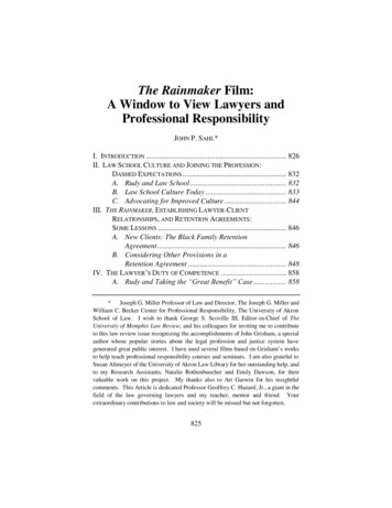
SWITCH PLATE DESCRIPTIONSLocator Light (1) - This green light will turn on when the two power cords are plugged into separatecircuits. Separate circuits are defined as outlets fed by circuit breakers on opposite sides of thecircuit breaker panel. This feature helps to prevent blown breakers. When the locator light (1) turnson, the heat exchanger will automatically turn on. If you can not get the locator light to turn on, usethe Heat Switch (2) to turn the heat exchanger on.Heat Switch (2) - This rocker switch turns the heat exchanger on and off, when the Locator light (1)is not on. The switch will light when ON.Mode Light (3) - This indicator light will turn on while the heat exchanger is actively heating. It willturn off when the heater has reached operating temperature. Normally, this light will be on most ofthe time as you do your job, but it may go out if you stop cleaning to move furniture or to empty or fillthe tanks.Vacuum 1 Switch (4) - This switch turns one vacuum on and off. The switch will light when ON.When operating with only one vacuum -- as when cleaning delicate fabric -- use Vacuum 1. Whencleaning carpet, use both Vacuum 1 and Vacuum 2 (5).Vacuum 2 Switch (5) - This switch turns the second vacuum on and off. The switch will light whenON. Use this switch when you want maximum vacuum lift. The CFM of both motors is the same asit is for one motor alone, since the vacuums are operated in parallel; however, the vacuum liftdoubles when both vacuums are running.Pump Switch (6) - This switch turns the pump on and off. The switch will light when ON.The pump in this machine is a “demand” style pump. This means the pump only runs when you areactually spraying. Once spraying stops, the pump stops running.➀➄➃➁➅OOOOIIII212 F➂8 - FORM NO. 56041563 / Rainmaker H
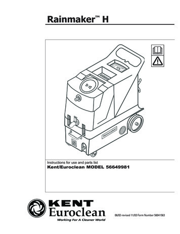
MACHINE WIRINGLineVAC 1SWGreen115VBlackWhite PowerCord #1NeutralWhiteVAC 2SWPUMPBlackWhiteSWFANBlackP3P2 IGHTThermostatHEATEXCHANGER ThermalFuse BlackWhiteBlack P1 115VBlackGreen PowerCord #2P4Dual CordSensor BoardBlackFORM NO.56041563 / Rainmaker H - 9
OPERATION12Inspect the machine, hoses, and cleaning tools for cleanliness and completeness.Fill the solution tank with warm water. Using warm water may be a benefit in cleaningeffectiveness, but do not use hot water (above 140 F / 60 C) in the tank. Add liquid cleaningsolution with a pH of between 6 and 9.3 Plug in the power cords. Do not connect both cords to the same outlet; the circuit locatorlight on the switch plate should light up. If the locator light does not come on, try differentoutlets until it does. If you are certain the cords are on separate circuits, turn the heatswitch on. CAUTION: using the heat switch when the cords are on the same circuit maycause the breaker to trip. NOTE: the cord with the red sleeve powers the heat exchanger.4 Attach the spray hose to the solution quick disconnect and the vacuum hose to the hosebarb on the recovery tank. Attach the other ends of the hoses to the cleaning tool.5 Turn the pump on and spray from the tool to make sure everything is working, and to fill theheat exchanger with water. NOTE: the pump has a built in pressure switch; the pump onlyruns when you are spraying.6 Allow the heat exchanger two minutes to reach operating temperature.7 Turn the pump on. Turn the vacuums on.8 Begin cleaning using the correct hoses and tool.9 Use defoamer in the recovery tank any time foaming occurs.10 Monitor water level in the solution tank. Do not let the pump run dry.11 When the solution tank gets low, turn off the pump, fill the solution tank, empty and clean therecovery tank.12 When finished with the job, remove any unused solution from the solution tank, and run afew gallons of clean water through the system.BALL FLOAT VACUUM SHUT-OFFPrior to using the machine, always check that the float filter is clean and the ball can travel freely.When the recovery tank is full, the ball float will rise and will shut off the vacuum flow to preventany more water from entering the tank. Turn off the vacuum, and empty the recovery tank.NOTE: if foam is present, or if the ball float is prevented from rising, the float will not be able tostop the air flow, and the tank may over fill.CAUTION!To avoid vacuum motor damage, always make sure the float filter is clean and the ball can travelfreely prior to using the machine. And always use a defoamer when foaming occurs.ELECTRIC CIRCUIT LOCATORThis unique, patented system is operated by a solid state circuit. It will inform the operator whenthe two cords are plugged into separate circuits by turning the circuit locator light (1) on. Thishelps to prevent tripping circuit breakers.NOTE: if the circuit locator light does not illuminate when the cords are plugged in, then bothcords are on the same circuit. Try other outlets with one of the cords until you get the locator lightto come on.CAUTION: if the Heat switch (2) is turned on when both cords are on the same circuit, thebreaker will trip.10 - FORM NO. 56041563 / Rainmaker H
USE AND MAINTENANCE12345678Use only liquid chemicals with a pH between 6 and 9 at the recommended mix ratios. Improperchemicals, or improperly mixed chemicals, can cause possible damage to the pump, seals, andother components.Turn the pump “off” when the solution tank is low on fluid. Do not let the pump run dry.Regularly clean any mineral or chemical deposits in the heat exchanger, lines and pump with amild acid descaler. Rinse the descaler out of the machine with a few gallons of clear water.Prior to each job, inspect, and clean if needed, the solution filter, the recovery tank float filter,and the drain hose.Make sure the airways are not blocked before each use.Inspect the carbon brushes on the vacuum motors once a year. Replace if worn down.Clean the Recovery Tank daily. Clean the body and wheels as needed.Keep the machine from extremes in temperatures.MAINTENANCE SCHEDULEDailyFLUSH LINES & PUMPXCLEAN VACUUM FLOAT FILTERXCLEAN SOLUTION FILTERXCHECK INLET AIRWAYSXDESCALE MACHINECHECK VACUUM MOTOR BRUSHESMonthlyYearlyXXFORM NO.56041563 / Rainmaker H - 11
12 - FORM NO. 56041563 / Rainmaker H
PART LIST RAINMAKERTM HItemRef. No. 0284556649989122DescriptionItemDrain Gate (Drain Gate Kit)Spout (Drain Gate Kit)Screw, 8-32 x .50 (Hardware Kit)Latch, Rubber W/StrikeO-Ring, Small (Drain Gate Kit)O-Ring, Large (Drain Gate Kit)Nut, Cast Aluminum, 1-1/2” (Drain Gate Kit)Recovery Tank, BlueHose BarbGasket (Hardware Kit)Lid, 6”, Clear Center, W/RingChain, 8” (also included in Solution Lid kit 56102812)Screw, 10-32 x .62 (Hardware Kit)Screw, 10-32 x .38 (Solution Lid Kit)Screw, 8-32 x .88 (Hardware Kit)Lock Nut, 8-32 (Hardware Kit)Float, Ball and Cage on ManifoldPVC ElbowHose Clamp (Hose Clamp Kit)Hose, Vacuum, 2” x 41”, RibbedHeat Exchanger, Complete (Heat ExchangerExchanger,, Complete)Hose Clamp (Hose Clamp Kit)Mount Bracket, Heat ExchangerHose, Braided SS (Heat ExchangerExchanger,, Complete)Washer, Brass (Heat ExchangerExchanger,, Complete)Washer, Fiber(Quick Disconnect Kit)(also included in Heat ExchangerExchanger,, Complete 56102825)Nipple, Stainless Steel (Heat ExchangerExchanger,, Complete)Bushing, Fiber (Heat ExchangerExchanger,, Complete)Heat Control Switch(Heat ExchangerExchanger,, Complete)(also part of Heat Repair Kit 56102819)Elbow, Brass(Heat ExchangerExchanger,, Complete)(also part of Hose Barb Kit 56102829)Coupling, Brass (Heat ExchangerExchanger,, Complete)Washer, Flt 3/16 (Hardware Kit)Lock Nut, 1/4 (Hardware Kit)acuum Motor Kit)Vacuum Motor, 120V (V(Vacuumacuum Motor Kit)Gasket, Vacuum Motor (V(VacuumManifoldBolt, 1/4-20 x 5.00 (Hardware Kit)Bracket, Vacuum Motor (Bracket Kit)Washer, Split Lock (Hardware Kit)Nut, Finish (Hardware Kit)Hose Barb, Straight (Hose Barb Kit)Handle, ChromeBolt, 1/4-20 x .75 (Hardware Kit)Quick Disconnect, 1/4 NPT(Quick Disconnect Kit)(also included in Heat ExchangerExchanger,, Complete 56102825)Flange, ExhaustLouver, W/ScrewsPVC Reducer (Cord Retainer 777879808283848586878889909192*Ref. No. 1141DescriptionCord Retainer (Cord Retainer Kit)Dual Cord Sensor PCBSnap Track, PCB Mount x 4” LGAxle Rod, Plated, 18.25”Wheel, 10” (Wheel Kit)Axle Cap (Wheel Kit)Cord, 12/3, 25ftHinge PinLabel, Kent / EurocleanBase Compartment, GraySolution Tank, BlueFilter, Pump InletNipple, PVC 1/2 NPTLid, Solution Tank (Solution Lid Kit)Hose Clamp (Hose Clamp Kit)Pump, 100PSI, 120VHose Barb, Elbow (Hose Barb Kit)Hose, 3/8”ID x 76”LGSwitch PlateScrew, #4 x 3/8” (Hardware Kit)Light, Green, 120VSwitch, SPST, W/CoverSwitch, DPDT, W/CoverScrew, 6-32 x 2.00 (Hardware Kit)Lock Nut, 6-32 (Hardware Kit)Fan, 120V (Fan Kit)Fan Guard (Fan Kit)Gasket, 7ftCord Wrap, BlackBolt, 1/4-20 x 1.00 (Hardware Kit)Washer, Flt SS 1/4 (Hardware Kit)Castor, 4”, No BrakeScrew, 10-32 x .62 (Hardware Kit)Lock Nut 10-32 (Hardware Kit)Bolt, 1/4-20 x .75 (Hardware Kit)Bracket, Mating (Bracket Kit)Bracket, Mating W/Hole (Bracket Kit)Bolt, 1/4-20 x 1.25 (Hardware Kit)Label, Warning* Not Shownrevised 11/03FORM NO.56041563 / Rainmaker H - 13
TECHNICAL SPECIFICATIONSVacuum Motor:Water lift:150”Air Flow:100 cfmAmp Draw:Tank Construction:16 amps, each cordRotationally molded polyethyleneSolution Tank Capacity:14 Gal. (53.2 L)Recovery Tank Capacity:12 Gal.(45.4 L)Application Flow:100 psiSolution Hose Length:15 ft. (4.5 m)Recovery Hose Length:15 ft. (4.5 m)Power Cord:10 in. (25 cm)Front Castors:4 in. (10.2 cm)2000 WattHeight:38 in (96.5 cm)Length:36 in (91.4 cm)Width:Machine weight:Ref. No. QtyTwo 25 ft. (7.6 m), High visability yellow, removableRear Wheels:Heat Exchanger:ItemTwo 2-Stage17.6 in (44.7 cm)83 lb (38 1556102825561028191111111111111KITSFan Kit (#79, 80)Wheel Kit (1 each of #50, 51)Solution Lid Kit (#8C, 60 / also includes #8A)Hardware Kit (#2, 7, 8B, 9, 9A, 25, 26, 30, 31, 32, 39, 44, 70, 77, 78, 84, 85, 87-89, 92)Hose Clamp Kit (#14, 17, 61)Vacuum Motor Kit (1 each of #27, 28)Drain Gate Kit (#1, 1A, 4-4B)Cord Retainer Kit (1 each of #45, 46)Hose Barb Kit (#33, 63 / also includes #24)Quick Disconnect Kit (#20A, 40)Bracket Kit (#30A, 90, 91)Heat Exchanger, Complete (#16, 19, 20, 21-24A / also includes #20A, 40)Heat Repair Kit ACCESSORIESSingle Bend Wand AssemblyDouble Bend Wand AssemblyExtractor Hand ToolVac Hose / Pressure Line 25ft.Vac Hose / Pressure Line 15ft.14 - FORM NO. 56041563 / Rainmaker H
NOTESFORM NO.56041563 / Rainmaker H - 15
VACUUM BALL-FLOAT SYSTEMTROUBLESHOOTING(120V)NOTE: The motors on these extractor models are controlled by AC voltage passing through the ON/OFFswitch.VACUUM MOTOR NOT RUNNING:1. Always unplug the machine before working on the wiring system.2. Open the machine to look for damaged or disconnected wires leading to the vac motor.3. Remove the screws from the switch plate. Gently turn the switch plate over and checkthe back of the switches to make sure no wires have pulled loose.MEASURING THE AC VOLTAGE THROUGH THE SWITCH:1. Connect a voltmeter to the terminals (with wires) on the vacuum switch being tested. Setthe AC voltage in the range of 120 volts, or more. (See Figure 1 to the right).2. Turn the vacuum switch “OFF”.FIGURE 1NOTE: There should beno voltage reading whenswitch is “OFF” (Step 3).3. With the switch in the “OFF”position, plug the #1 Cord (redsleeve) into an outlet andmeasure for NO AC voltage.4. Turn the switch “ON” and lookfor an AC voltage reading. (SeeFigure 1 to the right).Switch ON5. If the switch is notworking, replace it.Refertotheschematic and parts list for theparticular machine you areworking on.6. If the switch is working correctly,test the motor itself by connectingit directly to AC voltage.Opposite sidesof the switch
TESTING THE MOTOR DIRECTLY TO AC VOLTAGE:1. Unplug the power cords.2. Cut both the power wires leading from the vacuum motor, several inches from the motoritself. Leave enough length for reconnecting the wires. See Figure 2 below.3. Connect the motor wires (leading from the motor) to an AC jumper wire. See Figure 2.4. Plug the jumper into an outlet. Does the vacuum motor run? If the vacuum motor runs,unplug the jumper, visually inspect and/or use the “continuity tester” or “ohm meter” tofind the opening between the switch and motor wires. Refer to the wiring schematic foryour machine model. Repair.5. If the motor does not run, replace it. Refer to the parts list and schematic for your machinefor the correct part number. Refer to Vacuum Motor Replacement Instructions for stepson removal and installation.FIGURE 2NOTE:Donot removetheremove the moNOTE:Do notmotor to testtor it.to test.Step 2 & 3: Cut both power wires several inches from the motor and connect to an AC jumper wire.Step 5: Plug the jumperinto an outlet.
VACUUM BALL-FLOAT SYSTEMTROUBLESHOOTINGAquaProTM 300(120V)NOTE: The motors on these extractor models are controlled by AC voltage passing through the ON/OFFswitch.VACUUM MOTOR NOT RUNNING:1. Always unplug the machine before working on the wiring system.2. Open the machine to look for damaged or disconnected wires leading to the vac motor.3. Remove the screws from the switch plate. Gently turn the switch plate over and checkthe back of the switches to make sure no wires have pulled loose.MEASURING THE AC VOLTAGE THROUGH THE SWITCH:1. Connect a voltmeter to the terminals (with wires) on the vacuum switch being tested. Setthe AC voltage in the range ofFIGURE 1120 volts, or more. (See Figure1 to the right).NOTE: There should beno voltage reading whenswitch is “OFF” (Step 3).2. Turn the vacuum switch “OFF”.3. With the switch in the “OFF”position, plug the #1 Cord (redsleeve) into an outlet andmeasure for NO AC voltage.Switch ON4. Turn the switch “ON” andlook for an AC voltagereading. (See Figure1 to the right).5. If the switch is not working,replace it. Refer to theschematic and parts list for theparticular machine you areworking on.6. If the switch is working correctly,test the motor itself by connectingit directly to AC voltage.Opposite sidesof the switch
TESTING THE MOTOR DIRECTLY TO AC VOLTAGE:1. Unplug the power cords.2. Cut both the power wires leading from the vacuum motor, several inches from the motoritself. Leave enough length for reconnecting the wires. See Figure 2 below.3. Connect the motor wires (leading from the motor) to an AC jumper wire. See Figure 2.4. Plug the jumper into an outlet. Does the vacuum motor run? If the vacuum motor runs,unplug the jumper, visually inspect and/or use the “continuity tester” or “ohm meter” tofind the opening between the switch and motor wires. Refer to the wiring schematic foryour machine model. Repair.5. If the motor does not run, replace it. Refer to the parts list and schematic for your machinefor the correct part number. Refer to Vacuum Motor Replacement Instructions for stepson removal and installation.FIGURE 2NOTE:Donot removetheremove the moNOTE:Do notmotor to testtor it.to test.Step 2 & 3: Cut both power wires several inches from the motor and connect to an AC jumper wire.Step 5: Plug the jumperinto an outlet.
VACUUM MOTORREPLACEMENTAquaProTM 300(120V & 240V)BEFORE BEGINNING REPAIRS: Unplug the machine, empty all water from the tanks, openthe latches and prop the tanks up.VACUUM MOTOR REMOVAL:1. Check to be sure the machine is unplugged.2. Cut the ground wires (green/yellow) from the vac motor, about 3 inches from the insulatedbutt connector. See Figure 1 below. Leave enough wire for re-connection.3. Cut and remove the small tie wraps that secure the wiring together. See Figure 1.4. Locate and cut the 2 power wires from the vac motor, a few inches from the motor. Seefigure 1 below. Note the correct location of wires. Leave enough wire for reconnection.Leave the power wires connected to the vacuum control circuit board (if applicable).FIGURE 1STEP 4: Cut the 2 power cordsfrom the vac motor a few inchesfrom the motor.STEP 2: Cut theground wire(s)about 3 inchesfrom insulatedbutt connector(not shown).STEP 3: Cut and removesmall tie wrapsFIGURE 1
SolutionLinesExhaustHoseFIGURE 2FIGURE 3ExhaustHoseSTEP 5: Remove 3 nutsholding motor to mounting bolts. (3rd nut notshown).HeatExchangerVacuumMotorSTEP 6: Loosen hosebracket and slideexhaust hose down.5. Remove the 3 nuts which hold the motor to the mounting bolts. See Figure 2 above.6. Slide the exhaust vacuum hose (under the machine) down to free the exhaust port on thevacuum motor. You will have to loosen the hose bracket, located underneath the machine, inorder to move the bracket aside to free the exhaust hose. See Figure 3 above.7. G
2 - FORM NO. 56041563 / Rainmaker H INTRODUCTION This manual will help you get the most from your Kent/Euroclean RainmakerTM H. Read thoroughly before operating the machine. NOTE: Bold numbers in parenthesis indicate an item illustrated on page 7. This product is intended for commercial use only. PARTS AND SERVICE