Transcription
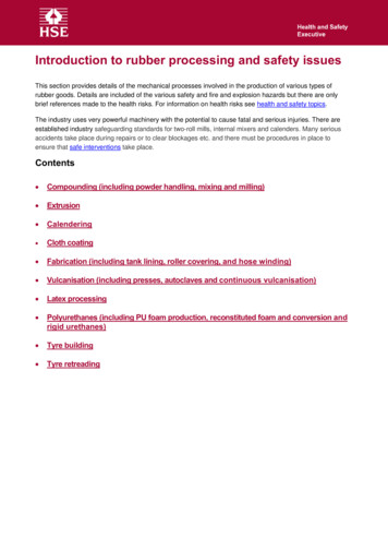
Introduction to rubber processing and safety issuesThis section provides details of the mechanical processes involved in the production of various types ofrubber goods. Details are included of the various safety and fire and explosion hazards but there are onlybrief references made to the health risks. For information on health risks see health and safety topics.The industry uses very powerful machinery with the potential to cause fatal and serious injuries. There areestablished industry safeguarding standards for two-roll mills, internal mixers and calenders. Many seriousaccidents take place during repairs or to clear blockages etc. and there must be procedures in place toensure that safe interventions take place.Contents Compounding (including powder handling, mixing and milling) Extrusion Calendering Cloth coating Fabrication (including tank lining, roller covering, and hose winding) Vulcanisation (including presses, autoclaves and continuous vulcanisation) Latex processing Polyurethanes (including PU foam production, reconstituted foam and conversion andrigid urethanes) Tyre building Tyre retreading
Compounding - powder handling, mixing and millingIntroductionCompounding involves the measuring and mixing together ofraw rubber, process oils, carbon black, bulk fillers, and rubberchemicals in pre-determined proportions, termed formulations.A rubber compounder can typically use between 100 and 200different ingredients to mix a range of formulations. Thefinished mixture is known as compound and is the materialthat is processed into rubber articles by moulding, extrusion,calendering etc.Carbon black storage handling area, bulk bagemptying. Note specialist HEPA vacuum forclean-up.Bale cuttingBefore being added to the mixer the rubber may need tobe cut into small pieces on a bale cutter or guillotine.These are usually down stroking machines, which shouldbe securely fenced with interlocking access gates. Feedopenings/tunnels should also meet safety reachdistances.The standard bale cutter is designed for 33.3kg bales.These are by far the most common machine but someof the larger old type shown below may still be in use.The standard 33.3kg bale can be fed directly into mostlarger rubber mixers but this small bale cutter isrequired to get the correct weight for the compoundrecipe.Standard bale cutter
For larger machines, during maintenance or cleaning the blades should be supported, as shown below:Some older machines have a fixed knife and an up stroking moving table. These should have interlocking guards toprevent access to the cutting area. Also, the trap between the lower part of the moving table and the edge of the floorshould be eliminated by safety fairings.Bale handlingMost of the rubber industry use mechanical handling such as the vacuum bale lifter. These are a reliable andlow cost option for handling the standard 33.3kg bales.Vacuum bale lifter
Fire and explosion hazardsMany of the rubber compounding additives are fire sensitive, particularly: Sulphurs and organic peroxides (used as curing agents); azodicarbonamide (used as a blowing agent in some open celled rubber/lattices).Particular care is required in storage areas to make sure incompatible materials, such as carbon black andsulphur, are adequately segregated.There have been incidences of dust explosions in powder handling areas. Many rubber compoundingadditives such as azodicarbonamide, calcium and zinc stearates, are known to be highly explosive when in afinely divided state. Design dust extraction and collection systems for use with potentially explosive dusts. Goodhousekeeping will minimise the risk of secondary dust explosions.MixingOnce the compound ingredients have been weighed out they are mixed togetherusing specialised machines capable of dealing with the high stresses involved inshearing rubber.Mixing can be either by internal mixing or external/open mill mixing which have very different safety problems.Internal mixing (eg. Banbury or Intermix mixers)The compound ingredients are fed into an enclosed mixing chamber via a feed hopper and mixed by theshearing action of two winged rotors and the walls of the mixing chamber. There is therefore a continuous nip.A powered ram or floating weight in the feed throat forces ingredients into the mixing chamber, which is usuallywater-cooled. The mixed compound is discharged via a sliding or hinged door below the mixing chamber,usually onto a two- roll mill, roller die, twin-screw extruder, conveyor, skip hoist, or wheeled truck.
Main mechanical hazardsFeeding ingredients and collecting compoundThe principal dangers and safeguards on a Banbury type internal mixer are: The rotors, via the feed opening (contact with rotors or falling in on larger machines)These risks can be guarded against by feed tables or conveyors placed in front of the feed opening, withadditional fixed side guards, where necessary.Safe reach distances should meet the requirements of Table 4 of BS EN ISO 13857: Safety of machinery.Safety distances to prevent hazard zones being reached by upper and lower limbs. The floating weight trap with the fixed bridge casting from either the feed opening or the rear inspection door.There should be sufficient clearance between the bridge and the fixed bridge casting to prevent a finger-trappinghazard. Prevent access by using the same safeguards as for the rotors. The floating weight and the lower edge of the front hopper door at the feed opening.The trap at the bottom of the weight is more dangerous. Operators are at risk when sweeping down or whenadding lubricant or other small ingredients. Where access to the trap is possible, interlock movement of thefloating weight with the hopper door. The front hopper door and frame as the door closes and the stops as it opens under powerWhere powered movement of the door creates a trapping hazard, it's operation should be via a hold-to-run control,located out of reach of the door or a two-hand control on the hopper itself. A front feed table preventing access willalso improve safety. Where bin-tipping units feed mixers, enclosing interlocking guards are required to preventaccess to shear traps created by the tipping mechanism.
Cleaning and maintenanceThe greatest hazard at internal mixers is during maintenance and cleaning, including, clearing of blockages. Operatorsmay need access to the mixing chamber/rotors, normally via the discharge opening. There is an incentive to do thisquickly as the compound hardens as it cools and a possible temptation to take shortcuts.Maintenance staff are more likely to use the rear inspection door.A trapped key interlocking system is required at both the rear inspection and discharge openings.Because of the size of internal mixers, operators can be working at three levels: the rear inspection door on the feedplatform; the discharge door at the motor platform; and the dump chute access at floor level. Communication istherefore difficult with the potential to increase risks.In addition, stored electrical, hydraulic and pneumatic energy as well as the potential energy from gravity fall of thefloating weight and inertia from run down of the rotors, may be released if the correct run down procedures are notfollowed.A trapped key interlocking system on all access doors, including a time delay and scotching of the floating weight isone means of preventing access to widely separated danger areas and is the accepted industry standard.The principle employed is that all sources of power are isolated and all stored energy is dissipated, beforeaccess is possible.
For further information see safe interventions and BS EN 12013 Rubber and plastics machines – Internalmixers - Safety requirementsInterlocking is by means of a main key exchange box, as shown below. All isolating keys have to be insertedbefore any access key can be released.When a guard is open, it traps the access key in it; likewise, when a part controlled by an isolating key is live,the key remains trapped in it. For example, before the rear inspection door shown above can be unlocked andopened, the compressed air supply has to be locked shut; with both ends of the floating weight cylindervented to atmosphere and the floating weight supported on a scotch pin, which is locked in position. Inaddition, the isolator for the main and hydraulic pump motors has to be locked open and the rotors have to beat rest. This condition is achieved by a time delay unit that releases an isolating key for the main exchangebox only after enough time has passed for the motor to come to rest. Access to the other hazardous parts isobtained by a similar process.
Drop door maintenance position on Banbury mixer with castell keyAccess hatch to hopper on Banbury mixer and details of castell keyDetails of Banbury castell key system
External or open mill mixing (two roll mills)This refers to mixing operations using horizontal two roll mills. The operator (usually known as a mill man)places the various ingredients in the nip formed between the rolls and mixes the compound by cutting it offthe rolls and re-feeding it into the nip until all the ingredients are added. Mills are used not only for blending ofcompound (open mill mixing) but also warming of pre-mixed compound (known as warming or cracker mills), or forcooling compound mixed in an internal mixer (known as dump mills).The main mechanical hazard is the nip between the main mill rolls in forward (and reverse) motion. Depending onthe design of the particular mill additional mechanical hazards may be created by ancillary equipment, includingtrapping between mill guides and rolls; cutting by mill knives; traps between the stock blender carriage and mill frame,and nips between the stock blender rolls; ejection of moveable mill trays; and trapping by movement of recovery beltconveyors (where fitted).For effective safeguarding of the main nip between the rolls there should be a sensitive trip bar, known as aLunn bar, fitted parallel to the mill rolls and positioned so that the operator works over it. The Lunn bar has provedeffective in reducing the number of fatal and serious maiming injuries at two roll mills from their historical level ofabout 20 per year in the 1950s - 60s,Operators drawn towards the nip will move the trip bar. This movement actuates the braking system and bringsthe rolls to rest before trapping the operator. Reliance on a single interlock switch for each Lunn bar is notacceptable. Each bar should have a positively operated switch at both ends.Positioning of the Lunn bar and the efficiency of the braking system are critical to its correct operation andhigh standard of maintenance inspection and testing are essential. BS EN 1417 Plastics and rubber machines —Two-roll mills — Safety requirements provides details for the performance criteria for the Lunn bar and brakingsystem. This includes a requirement for automatic roll separation and reversal on operation of the Lunn bar.
ExtrusionIntroductionExtrusion involves forcing uncured rubber through a die under pressure to form a shaped profile or sheet. Rotatingknives (or die face cutters) can then convert extruded material into pellets or slugs for further processing.Rubber can be dumped direct from an internal mixer into an extruder below it as an alternative to two roll mills forfeeding calenders. An extruder feeding directly into a two-roll calender is known as a roller die extruder.Roller-die for Banbury mixerPallet of finished compoundTriplex extruder
Mechanical hazardsScrew (or scroll) extrudersThese machines convey uncured rubber forwards down the barrel and through the die by the action of a rotatingscrew. They produce continuous extruded sections such as cable covering. Single screw versions are most commonbut twin or triple screw extruders may be used for complex products such as cable sheathing where they may beseveral layers of compound (co-extrusion).Screw extruders can be either hot fed, with warmed pre-mixed rubber, or cold fed. Temperature control isgenerally by water circulating in a jacket around the extruder barrel, screw and die head. The rubber is normallyfed in strip form, taken off a two-roll mill.The main mechanical hazard on a single screw rubber extruder is the trap between the rotating screw and thefixed parts of the machine at the feed opening. Feed systems can also create additional trapping hazards such as acrammer feed device.Where rubber is fed in strip form, feed rollers are often used to guide the strip into the feed opening. These maybe free running, or driven in contra- rotating directions so that the strip remains under constant tension. Crammerfeeding with an additional secondary screw is also common.Use adequate fixed or interlocking guards to prevent access to the screw and other dangerous parts, whateverthe feeding arrangement. The simplest arrangement is a series of free running rollers to guide the rubberstrip. These must be spaced to prevent finger access to the screw. Where hinged feed hoppers or feedingdevices are used these should be positively interlocked with movement of the screw.Where powered movement of screen plates (perforated plates which 'strain out' contaminants) create a hazard,additional guarding may be required. The die breaking or being ejected is also a potential hazard. Althoughnot common it occasionally occurs on machines with interchangeable dies where the die or die securing device isworn or inadequate. Regular inspection and maintenance are important.For further information on screw extruders see BS EN 1114. Part 1 covers the extruder, Part 2 die face pelletizers,and Part 3 haul-off devices.Haul-off unitsA lot of reported injuries at extrusion lines occur at haul-offs downstream. These draw off the extruded profilecontinuously to be cured or cooled, and cut to length or reeled up. They operate by pulling the profile by meansof friction between the product and two counter-rotating tracks, belts, or rollers set one above the other. Trappinghazards typically occur between the tracks at the feed position; between the extruded profile and the tracks; andbetween the drive pulleys and tension rollers, and the tracks.When assessing the risk consider: the speed of movement; the forces and pressure applied (including the rigidity of the tracks and the profile); and the method of operation.Use of fixed or interlocking guards should be possible in most cases but guarding of the feed intake may not be soeasy because of the need to allow for different size profiles. The feed opening in the guard should provide adequateprotection for the largest profile handled. Tunnel guards profiled around the sides of the tracks at the feed intake, andmounted on the top and bottom tracks may therefore be a better option. Use of free-running horizontal guide rollers infront of the feed opening will further restrict access.Feeding of product during start-up usually presents the greatest risk to the operator. Where there is a significanttrapping hazard, automatic feeding devices should be used, or feeding should be done with the haul-off stationary.
Where this is not possible a safe system of work is essential. Operate the haul-off at reduced speed, via a hold-to-runcontrol, which should be under the direct control of the operator. BS EN 1114. Part 3 permits a maximum feedingspeed of 200mm/second under these circumstances and gives details of more guarding options.Ram extrudersHere, a roll of rubber compound or 'pig' is placed into the extruder barrel with the die swung out of position; thedie is then closed, either manually or under power, and the rubber is forced through the die by the forward actionof a powered ram. The most common type is the Barwell extruder.Because the extruder is loaded with individual batches of rubber, these machines cannot produce continuousprofiles but produce a strip or pellet for further processing. Where pellets or slugs are produced, the die mayhave a rotating knife (die face cutter).The main mechanical hazard is the trap between the closing die and the barrel on machines where there ispower assisted die closure. Accidents have occurred when a second member of the extrusion team hasattempted to assist die closure by trimming back the rubber during closure.Die closure should be under two hand control and safe systems of work adopted to exclude third parties.Interlock movement of the ram with the die, so that ram movement is not possible with the die swung out ofposition. Rotating knives of die face cutters should have an interlocking guard with appropriate time delay toaccount for run down.
CalenderingIntroductionA calender is a machine with a number of horizontal rolls (sometimes called bowls), heated or unheated, throughwhich material and/or rubber is passed under pressure. They can create either a rubber sheet of a requiredthickness, or apply a thin layer of rubber onto a cloth liner. This is known as frictioning or combining.Cushion calenderCalenders can have two, three or four, rolls of various sizes and configurations. The diagram shows a 4-roll calenderand the material circuits for bilateral coating either textile of metallic fabric or cords.Mechanical hazardsThe main mechanical hazards at calenders are caused by nips between the rolls, for both the rubber andfabric feed. This is a particular problem during threading up, cleaning and maintenance. There is also arunning nip at the take-off or wind-up devices.Depending on the design, there may be other mechanical hazards caused by : auxiliary rollers for embossing or tensioning; cooling drums; cutting devices; stock guides
Rubber feed nipOne of the simplest methods of preventing finger access to the nip is to use a fixed nip bar that extendsthe length of the rolls, positioned no more than 6 mm from the surface of the roll to prevent a trappingpoint.When rubber is fed manually into the nip access can also be prevented using the feed table as a distanceguard, with integrated mesh guards at either end. Dimensions should meet the requirements of BS ENISO 13857:2008 Safety of machinery. Safety distances to prevent hazard zones being reached by upperand lower limbs.There is also a risk of the operator getting entangled with materials and dragged over the table towardsthe nip. To control this risk position a horizontal interlocking trip bar just below and slightly to the front edge ofthe feed table so that the operator cannot approach the nip between the rolls without hitting the trip bar. Thisshould then operate two limit switches, one at each end of the bar and bring the rolls to rest in not more thanan eighth of a revolution.If closer approach is needed for feeding then an interlocked ‘manager guard’ should be used, with dimensionsmeeting the requirements of BS EN ISO 13857:2008. This consists of sturdy parallel bars that prevent fingeraccess to the nip. A push-stick designed to fit between the bars helps feed the rubber to the nips.Fabric feed nipWhen combining, fixed nip guards are often not practical because of the varying thicknesses of material beingcalendered and the need for lower roll adjustment. A ‘limited movement’ guard can therefore be used whichconsists of an interlocking guard of closely spaced bars or hoops/loops. The guard pivots around a horizontal axisand if a hand is drawn between the guard and a roll, the guard operates a position sensor, which stops therolls. After the hand is removed the guard returns to its rest position but this does not cause restarting.Take-off and wind-up devicesRunning nips at various take-off and wind-up rollers, including the coated cloth wind-up mandrel, can create trappingand entanglement hazards. When assessing the risk it is important to take into account: the machine speed;whether the roller or mandrel is powered or not;the sheet tension;the strength and tackiness of the material;the need for approach.Most rubber sheet and rubberised fabric will be very strong when under tension, and capable of inflictingserious injury.Use automatic tensioning equipment, as it should not be necessary for operators to feel or manually adjustthe tension of the cloth whilst it is in motion. Use devices such as slipping clutches to regulate tension, and'banana' or bowed rollers to reduce creasing, as they will also reduce the need for approach.Where there is a significant risk of injury, prevent access to the running nip by interlocking guards, pressuresensitive mats or photoelectric safety systems.For start up, fix the cloth liners to the mandrel whilst it is still stationary.
Adding the fabric liner backing sheet to a cut belt to prevent rubber belt sticking to its self.Note: The backing sheet is re-usedThreading up and maintenanceThreading up and maintenance, including clearing of blockages, can create additional hazards. This is because aclose approach to the nips may be necessary. Where possible threading up and maintenance should be with thecalender stationary and the rolls separated.Where it is necessary to reverse the calender drive, for example to clear blockages, it will create new nips. Reversemovement should be via a hold to run control and at a suitably slow speed, termed an inch device. All operatorsshould also be excluded from the danger areas. If there is more than one operator there should also be flashinglights or an audible alarm. Also, provide sufficient emergency stop buttons on both sides of the calender and at theauxiliary feed and take-off devices.More information on safety during the threading of calenders can be found in SIM 03/2009/07 Safety duringthe XVH of calenders in the rubber DQG SODVWLFV LndustryOther mechanical hazardsThese may include: crushing at the trap between a moving calender roll surface and a fixed part of the machine; crushing between the stock guides and the calender roll; cutting hazard from the blades or trimming knifes; crushing between a swinging feed conveyor and the machine framework; trapping between contra-rotating cooling drums or between drums and fixed parts of the machine; the roll nip adjustment mechanisms.Appropriate procedures should be in place for cleaning and maintenance which are both potentially high risk activities.For further guarding options and requirements, see BS EN 12301 Plastics and rubber machines - Calenders –Safety Requirements
Cloth coatingIntroductionCloth coating involves the impregnation of cloth, mostly synthetic rather than cotton, with a rubber solution toproduce a waterproof or chemically resistant fabric for use in waterproof clothing, tarpaulins, sails, dinghyfabrics etc. A range of rubbers and organic solvents are used to produce the rubber solution or 'dough'.Natural rubber, synthetic polymers such as chlorosulphonated polythene (Hypalon) and urethanes are themost widely used rubbers. Commonly used organic solvents include toluene, xylene, acetone, MEK, andpetroleum naphtha blends (n-hexane based) SBPs 1-5.Rubber compound, produced by internal or open mill mixing, is soaked in solvent before mixing to a solutionwith the consistency of light dough. Colours, other additives and more solvent may be added during mixing.Some fabrics such as nylon require pre-treatment to achieve a good bond with the rubber. MDI is most widelyused as a pre-dip, prior to the spreading process. Most fabrics are pre-dried, usually in a hot air oven, prior tocoating.Spreading machines evenly distribute the rubber solution onto the cloth as it is drawn under it, using anadjustable blade, known as a doctor blade. The coated fabric is then drawn into a drying oven to evaporatethe solvent. The cloth is then passed over cooling rolls and wound up, either at the front or back of themachine. Embossing rollers positioned after the oven produce the desired surface finish. The process isusually repeated a number of times to achieve the required degree of proofing; the coating thickness at eachpass is controlled by adjusting the height of the doctor blade.The rubber solution is fed onto the cloth via a trough or tray. Solutions that are more viscous are added as a'roll' of material directly onto the cloth and adjacent to the doctor blade. The speed of coating machines canvary considerably, from less than 10 metres per minute to over 100 metres per minute. The slower, usuallyolder, spreaders often have steam-heated chests to drive off the solvent. High speed machines tend to useindirect gas-fired evaporating ovens.The coated cloth can be vulcanised by either continuous curing, eg Rotocure, or more commonly by dustingthe coated cloth with a starch based agent to prevent sticking and then re-rolling it and curing it in batches ina steam autoclave.Mechanical and other hazardsThe risk of entanglement and shear trapping hazards at dough mixers should be controlled by havinginterlocking lids, and/or interlocking enclosing guards.As many of the solvents are highly flammable suitably protected electrical devices are required. Also, controlthe risk from static charges. Precautions at evaporating ovens should include explosion relief and flamefailure devicesSpreading machines can have nip and running nip hazards, particularly at the cloth wind-up, embossing, andcooling rollers. Higher production speeds will increase the risk and fixed or interlocking guards or otherprotective devices will be required. At slower speeds and for inaccessible nips, trip wires fitted to emergencystops may be acceptable, if justified in the risk assessment.Safeguarding may also be required for any running nips when the cloth is re-rolled after curing.
Fabrication (including tank lining, roller covering and hose winding)Fabrication covers a range of operations where rubber and other materials are assembled to produce finishedarticles or components. Rubber lining operations and hose building present particular hazards.Rubber lining operationsRubber sheet may be bonded to metal components including valves, pipes, tanks, and rollers, and thenvulcanised to provide a tough, corrosion resistant lining or covering. The main hazards common to all rubberlining operations are the health and fire hazards associated with the use of solvents for degreasing metalcomponents and solvent-based bonding agents. Tank lining and roller covering have additional hazards.Tank liningRubber lining of tanks or other enclosed structures can be either in a factory or on site, but in either caseusually involves the following operations: Clean out the vessel (usually by steam); Prepare the vessel surface (usually by shot blasting); Apply rubber solution, or bonding agent (usually toluene or n-hexanebased); Place sheets of rubber in position (sometimes pre-warmed); Vulcanise (using hot water or steam).These operations present a number of significant hazards, including those associated with entry into confinedspaces; shot blasting; use of flammable and/or toxic solvents; and use of pressure vessels.For any work involving entry into confined spaces, strictly controlled safe operating procedures and highstandards of operator training are essential. Detailed guidance can be found in the Safe work in confinedspaces Approved Code of Practice, Regulations and guidance (L101) and Safe work in confinedspaces Leaflet INDG258.Breathing apparatus will protect the operator against the health hazard associated with solvent use but a fireand explosion hazard may remain. Therefore, use a non-flammable solvent wherever possible. Forcedventilation should reduce the concentration of flammable vapours in air to below one quarter of its lowerexplosive limit. If you can not do this then all potential ignition sources should be excluded and speciallyprotected hand lamps used. Equipment should also be earthed.Small rubber-lined articles are usually cured in an autoclave. Larger tanks or vessels may be converted intotemporary steam receivers by blanking-off the entry point and admitting steam up to 20psi. The requirementsof the Pressure Systems Regulations will then apply. Establish the vessels' safe operating limits and fitprotective devices to protect against and warn of system failure.Roller coveringSteel rollers are covered with rubber or polyurethane sheet as this will provide them with a controlled measureof resilience. They are then cured in autoclaves. In addition to health risks, there is also a danger of fire fromthe solvents and explosion from the fine cured rubber dust produced when grinding the covered roller to size.The majority of reported fires in rubber factories involve finely divided vulcanised rubber and dust. Extractionat rubber grinding machines, depending on the particle size, will generally need to be designed and installedfor use with potentially explosive dusts. Consider where the dust collection unit is located and in particularwhere explosion relief vents to. Good housekeeping will minimise the risks of a secondary dust explosion. Ifthe operator attempts to take too deep a cut, it will cause the rubber to overheat and increase the fire risk.
For more information see Safe handling of combustible dusts: Precautions against explosions(HSG103) and SIM 03/2009/08 Hazardous area classification for explosible dusts in the rubber andplastics industriesHose windingIntroductionRubber hose has a wide variety of applications such as car parts for power steering, air conditioning systems,etc. The most common types are Nitrile and EPDM rubbers but silicones and flouroelastomers are moresuited to high temperature applications.The basic equipment used to produce hose consists of a metal mandrel supported in rotating chucks, one ofwhich is driven. Standard metal working lathes are commonly used.To build up a hose, layers of rubber strip and fabric, with wire or rope used as reinforcing material, are woundonto the mandrel. The wire or rope is applied under tension. The final winding operation involves theapplication under slight tension of nylon webbing known as a spurle. The complete hose assembly
The compound ingredients are fed into an enclosed mixing chamber via a feed hopper and mixed by the shearing action of two winged rotors and the walls of the mixing chamber. There is therefore a contin uous nip. A powered ram or floating weight in the feed throat forces ingredients into the mixing chamber, which is usually water-cooled.