Transcription
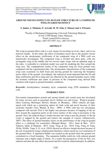
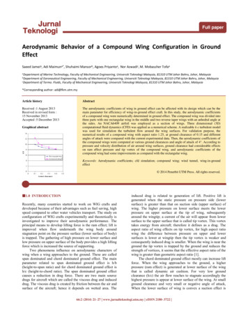
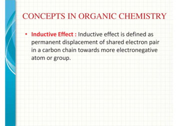
EFFECT OF COMPOUND FORMULATION ON THE PRODUCTION ANDPROPERTIES OF EPOXIDISED NATURAL RUBBER (ENR-25) FOAMSZ.M. Ariff, N.A.A. Rahim and L.C. LowSchool of Materials and Mineral Resources Engineering,Engineering Campus, Universiti Sains Malaysia,14300 Nibong Tebal, Penang, Malaysiae-mail: zulariff@eng.usm.myIn this study, Epoxidized Natural Rubber (ENR-25) formulations are compounded and tested to obtain a stableexpandable rubber foam as well as to determine the foam cell physical morphology and its mechanical properties. Theexperiment was carried out by employing different ratio of rubber blend between ENR-25 and natural rubber (SMR-L),different amount of blowing agent which is Sodium Bicarbonate and different ratio of accelerator betweenTetramethylthiuram-disulfenamide (TMTD) and N-cyclohexyl-2-benzotiazolsulfenamide (CBS). Cure characteristics ofthe compounded rubber were determined using Monsanto Rheometer and the expandable rubber foam is produced usingcompression moulding technique with utilization of heat transfer process. The generated foam cell morphology isanalyzed using image analyzer and SEM while the mechanical properties of the foam are examined by using Instronmachine to determine its compression stress. On the other hand, swelling test using the Flory-Rhener equation is alsodone to support the substitute results. The data shows that at the ratio of 60 phr ENR-25 and 40 phr SMR-L is able todeliver stable rubber foam. Furthermore, increasing the amounts of blowing agent evidently increased the foam cellsize, inducing smaller cell in between the foam cell wall, decreasing the value of compression stress and compressionset. It was also observed that increasing the ratio of CBS in the compounded rubber will increase the cell size, creatingthicker foam cell wall, increasing the value of compression stress and compression set.IntroductionTo date, there has been great development in themaking of foam product and mostly for the applicationsof cushioning to make mattress, house whole used andothers. Beside these applications, foam also has a gooddemand for engineering applications such as packagingproduct, thermal insulations for buildings and also inautomotives industries. The main advantage of foamover other type of materials is its low density whichleads in creating lightweight product. Furthermore, theproduction of foam goods itself covers 10% of totalusage of polymer materials and generally 70% of thefoam products are made using polyurethane followedby polystyrene and polyvinyl chloride [1].Although thermoplastic are well known features inproducing a foam, thermoset and elastomer also hasbeen used to produced a foam but its rarelycommercialize due to lack of research done. Latex foamis most favourable materials since it provides propertiesin elasticity hence contribute in a lot of generalapplications. But unfortunately, to preserve the latexmilk in a liquid form before going through otherprocess, it involves in adding an amount of ammonia toprevent it from coagulation and technically ammonia ishazardous to the environment. For elastomer, thechallenge to make foam is contributing to its highviscosity and tedious formulations. Formulations play avery important role in altering the overall properties ofthe generated foam and sometimes mistakable or notcompatible formulations will lead to cell collapse oreven no foam are produce [2]. Different amount andtype of blowing agent used will effect the overall cellgrowth and distributions of the cell growth of the foam.There has been research done to study the rubber foambut most of them utilized combination of two blowingagent, mostly between ADC and sodium bicarbonate[3,4].There limited literatures that covers the usage onlysodium bicarbonate due to low volume of carbondioxide release during the decomposition. Therefore, inthis particular study only sodium bicarbonate is put tothe test to evaluate its capability in promotingexpansion to the rubber compound. Besides that,various types of formulations are also formulated todetermine the change to the rubber foam.ExperimentalMaterials and FormulationsENR-25 with 25 mol% epoxidation and SMR-Lwas supplied by Malaysian Rubber Board. Thevulcanization additives such as Zinc Oxide (ZnO),silica S, stearic acid, l-2-benzotiazolsulfenamide(CBS) and sodium bicarbonate were obtained fromBayer (M) Sdn. Bhd. Whereas, sodium bicarbonate wasProceedings of the Polymer Processing Society 24th Annual Meeting PPS-24 June 15-19, 2008 Salerno (Italy)
purchased from Merck, Inc. All materials were used assupplied and the complete formulations are shown inTable 1,2 and 3Table 1: Formulation for different ratio of rubber blendbetween ENR-25 and TMTD2.52.52.5CBS111Sulphur0.50.50.5Stearic Acid222Silica555Zinc Oxide444Table 2: TMTDCBSSulphurStearic AcidSilicaZinc Oxidefor different amount of 5254Table 3: Formulation for different ratio of acceleratorbetween TMTD and 50.5Stearic Acid2222Silica5555Zinc Oxide4444Mixing and Cure Characteristic MeasurementThe rubber compound was compounded with otheringredients based on the formulations of the mixture ina two-roll mill; model XK-160, in accordance withASTM method designation D 3184-80. The curingagent which is sulphur and the blowing agent wereadded at the end of the process. The cure characteristicsof the compounded rubber were determined by using a100 C. After moulding, it was directly transferred intoan oven set at a temperature of 150 C for 30 minutes.The generated expandable compound was then takenout from the oven and allowed it to cool down underroom temperature.Morphological StudyStudies on morphology of various formulationsfoam were carried out using a scanning electronmicroscope (SEM), model Leica Cambridge S-360.Utilizing the obtained SEM micrographs, imageanalyzer software, Image Pro Plus, is used to obtain theaverage cell size produced parallel and perpendicular tothe foaming direction. The results of average cell sizewere determined from measurement at 20 differentlocations of the captured image. The cell amount wascalculated from the knowledge of average cell size,solid rubber density and foam density.Measurement of Physical PropertiesThe crosslink density test was studied in tolueneaccording to ASTM D 471-98 using the Flory-Rhenerequations. To find the density of the solid vulcanizedrubber without expansion, the test was done based onASTM D1817-96. Relative foam density was measuredusing equation in accordance with ASTM D3575-93.Whereas, the foam expansion ratio was calculatedbased on the following equation.Expansion ratio H f HoHowhere,Hf Height after foamingHo Initial height before foamingMeasurement of Mechanical PropertiesSample with the dimension of 50x50x23 mm wascut without any skin layer exists on the top and bottomof the rubber foam. Then, it was tested using Instronmachine with a cross head speed of 25 mm/mindownwards to measure its compression stress. Forcompression set, the sample with the dimension of50x50x18 mm was cut and put through the compressionplate and compressed until 50% of the foam originalthickness before exposing it in an oven with thetemperature of 70 C for 24 hours. The percentage of thecompression set is calculated using the equationsbelow.t trCompression set o(1) 100%to t cMonsanto Rheometer model MDR 2000 at 150 C.Sample PreparationThe rubber compound is moulded in the discshaped with the diameters of 160 mm and 6 mm depthusing the hot press for 1 minute at the temperature ofto Initial thicknesstr Thickness after recoverytc Thickness after compression setProceedings of the Polymer Processing Society 24th Annual Meeting PPS-24 June 15-19, 2008 Salerno (Italy)
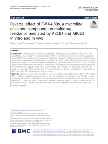
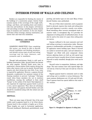
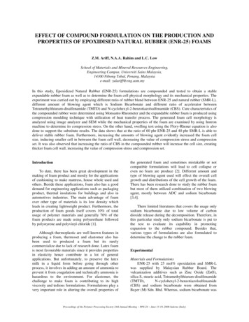
Results and DiscussionThe Effect of Different ratio of Rubber Blend betweenENR-25 and SMR-LRheologyThe rheograph results between the threecompounds with different ratio of rubber blend betweenSMR-L and ENR-50 shows more or less similarpatterns as shown in Figure 1.1098100 phr EN R-25To r que (dN m )7680 phr EN R-25560 phr EN R-2543phr ENR-25. This is similar to findings reported byIsmail and Leong [6] for SMR-L blend withChloroprene Rubber (CR). This scenario occurred dueto lower viscosity value of the SMR-L than that of CRwhich results in occurrence of an interphase betweenthe two rubber blend which created incompatible blend.In these cases, similar situation can be projected to existwith the rubber blend between ENR-25 and SMR-L.Foaming ProcessFrom the observation after 1 hour of foamingprocess, foam produced form the blend of 60 phr ENR25 proved to be a stable foam instead of 100 phr ENR25 and 80 phr ENR-25 as shown in Figure 2.Top View100 phr ENR-25Side View100 phr ENR-2580 phr ENR-25 20 phr SMR-L80 phr ENR-25 20 phrSMR-L60 phr ENR-25 40 phr SMR-L60 phr ENR-25 40 phrSMR-L210036912151821242730Time (min)Figure 1: Reograph for different blend ratio of rubbercompound between ENR-25 and SMR-LRegarding the data generated in Table 4,Table 4Cure characteristic data for different blend ratio of rubbercompound between ENR-25 and SMR-LProperties100 phr 80 phr60 phrENR-25 ENRENR2525ML (dNm)0.010.170.09MH (dNm)6.485.876.26Optimumcuretorque, T90 (dNm)Optimum curetime, t90 (min)Scorj time, t2 (min)5.635.385.575.445.344.921.931.971.89Minimum torquetime, t1 (min)0.880.930.91the optimum cure time T90 exhibit higher value withincreasing ratio of ENR-25. According to Ismail andcoworkers [5] in their research on the curecharacteristic for the blend of NBR and ENR-50, provesthe cure characteristic rose slightly with adding morecontent of ENR-50. Basically the experimental blendfor SMR-L and ENR-25 seems to follow similar trend.These particular phenomena happen due to theactivation of crosslinking on epoxy group attached tothe backbone of the ENR-50 rubber chain.Figure 2: The view of different blend ratio of rubber compoundbetween ENR-25 and SMR-L after foaming.Referring to Landrock [7], foaming process will gothrough two stages which are expansion on the earlystage and followed by shrinkage. Expansions are causedby the thermal degradation of the blowing agent whileshrinkage occurs when blowing agent has decomposedcompletely. The cure characteristic data shown in Table5As for MH which is the maximum torque, evidentlythe viscosity for 80 phr ENR-25 had lessen thoroughlycompared to the corresponding 100 phr ENR-25 and 60Proceedings of the Polymer Processing Society 24th Annual Meeting PPS-24 June 15-19, 2008 Salerno (Italy)
4.70E-05-3provides details where as the amount of ENR-25increases, the cure time t90 will evidently decreases.Since the formulation with 60 phr ENR-25 cured fastercompared to 100 phr ENR-25 and 80 phr ENR-25 theserevealed that the crosslinking has already completedwhen the blowing agent has fully decomposed for 60phr ENR-25. Whereas, formulations with 100 phr ENR25 and 80 phr ENR-25 took longer time to complete thecrosslinking. Consequently after the blowing agent hadcompletely decomposed, the cell wall is not fully curedand strong enough to uphold the rubber mass andslowly, it will collapse with time. This can be clearlyseen in Figure 2.It can be clearly observed that all the compoundedrubber shows slight differences. From the rheographvalue of MH, t2, T90 and t90 seems reduce with addingmore content of sodium bicarbonate. Previously, Ariff[8] has investigated on the viscosity of the compoundedfoam concluded that increasing amount of blowingagent into the compounded polymer will result inreleasing more volume of gas. Normally for sodiumbicarbonate, majority of the gas release is carbondioxide. Carbon dioxide consist small molecules whichallowed it to easily absorb into the compounded rubberand reduce the matrix viscosity. As a result, it directlyaffects the crosslinking rate due to higher volumetricgas decomposition in the vulcanized rubber. The data issupported by the crosslink density results shown inFigure 4Crosslink Density (mol/cm )Table 5Cure characteristic data for different blend ratio of rubbercompound between ENR-25 and SMR-LProperties100 phr80 phr60 phrENR-25 ENR-25ENR25ML (dNm)0.010.170.09MH (dNm)6.485.876.26Optimumcure5.635.385.57torque, T90 (dNm)Optimum cure time,5.445.344.92t90 (min)Scorch time, t2 (min)1.931.971.89Minimumtorque0.880.930.91time, t1 -05246810Amount of Sodium B icarbonate (phr)The Effect of Adding Different Amount ofSodium BicarbonateFigure 4: Crosslink density for different amount ofsodium bicarbonateRheologyThe research was continued with the effect ofadding different amount of sodium bicarbonate. Sincethe usage of 60 phr ENR-25 are capable of producing astable foam without any shrinkage, so the formulationare adapted for these study and the amount of blowingagent introduced are altered. Based on the rheographgenerated in Figure 3.10which also show increasing value of crosslink densitywith increasing content of blowing agent.Morphology and Physical Properties of the Rubber FoamThere are various factors influencing the foammorphology such as temperature, pressure, type ofpolymeric materials and the formulation used. Theeffect of chemical blowing agent introduces willdefinitely effect the cell distribution and the cell sizedepending on the type of blowing agent used, loadingamount and the blowing agent particle size [2].9Torque (dNm)8Sodium 4 phr7Sodium 6 phr65Sodium 8 phr4The investigation also observed that, the cell sizegrow larger when higher amount of sodium bicarbonateregardless of foaming direction, i.e. perpendicular orparallel and this is shown in Figure 5.321003691215 1821242730Time (min)Figure 3: Reograph for different amount of sodiumbicarbonateProceedings of the Polymer Processing Society 24th Annual Meeting PPS-24 June 15-19, 2008 Salerno (Italy)
1Size (mm)0.8Parallel Axis0.6generated among the polymer chain. The crosslinkingwill form a network consisting of higher packingpolymer chain and results in increasing foam relativedensity (refer Figure 7).PerpendicularAxis0.45.50.20.4300.468Figure 5: Cell size for different amount of sodiumbicarbonateRelative density4Amount of s odium bicarbonate(phr)3.50.372.50.341.50.310.50.28The cause can be related to reduction in matrixviscosity due to partially complete crosslinking andconsequently produced larger cells with increasingamount of blowing agent. A graphical representation ofthis occurrence can be seen in Figure 6.Perpendicular Axis(a) 4 phrParallel Axis(4 phr)0.25Expansion ratio (%)4.5-0.5468Amount of sodium bicarbonate (phr)Figure 7: The effect of relative density and the ratio offoaming expansion for different amount of sodiumbicarbonateAgain, the data is supported by the calculated cellamount which is tabulated in Table 6.(b) 6 phr(6 phr)(c) 8 phr(8 phr)Figure 6: Cell distributions for different amount ofsodium bicarbonateIncreasing cell size and thinning effect of the cell wallwill directly alter the foam density as well as foamexpansion ratio. Relatively, the foam density is reducedand the ratio of foam expansion will also increase.On the other hand, the foam relative density ishighly influenced by the chemical crosslinkingTable 6Cure characteristic data for different amount of sodiumbicarbonateProperties4 phr6 phr8 phrSodiumSodiumSodiumML (dNm)0.110.070.09MH (dNm)6.526.486.26Optimum5.865.725.57cure torque,T90 (dNm)Optimum5.225.044.92cure time, t90(min)Scorch time,1.561.681.89t2 (min)Minimum0.810.930.91torque time, t1(min)The result shows that the amounts of cell decrease withincreasing amount of sodium bicarbonate. Logically,the cell size will increase when more open cells areproduced. The data are strongly connected to Figure 6which showed the foam morphology present more opencell exist as increasing amount of sodium bicarbonate.Mechanical PropertiesPrevious data of its physical properties will director indirectly affect the foam mechanical properties. Asfor compression set, it is determine that by adding moresodium bicarbonate, less value of compression set areobtain. According to Ariff and colleagues [9], the cellsize plays an important role in compression set test.Proceedings of the Polymer Processing Society 24th Annual Meeting PPS-24 June 15-19, 2008 Salerno (Italy)
Normally the bigger cell will collapse first rather thanthe smaller ones due to microscopic deformation at thecell wall but the results are in reverse direction asshown in Figure 8.bicarbonate displayed the lowest value followed by 6phr and 4 phr as shown in Figure 9.150Compression Stress (KPa)Compression Set (%)504030201204 phr906 phr8 phr6030100001020468Amount of Sodium Bicarbonat (phr)405060Supposedly, bigger cell sizes are prone to undergomicroscopic deformation rather than the smaller size.But, in this situation it is possible that during thedeformation the smaller cells in between the cell wallwere not damaged or ruptured and recovered to give abetter recovery for the foam.Generally, as the cell morphology changes, thefoam will also give different value of compressionstress. It is discovered that the compression stress isreduced with increasing content of sodium bicarbonateas shown in Table 7.Table 7Data for compression set for different amount ofsodium bicarbonateSodiumSodiumSodiumRubber foam bicarbonate bicarbonate bicarbonate(8phr)(4 phr)(6 phr)0.8792 0.0080.7125 0.0110.5451 0.02117.598 0.02414.687 0.03112.707 0.01846.09 0.01746.51 0.00934.24 0.01469.13 0.01267.93 0.01466.66 0.009Figure 9: Compression stress for different amount ofsodium bicarbonateBeside that, increase in cell size which is parallel to thefoaming direction will causes longer distance for theupper and lower cell wall to be in contact resultinghigher maximum strain. A sudden drastic change in thecompression stress value for all the foam is caused bythe effect of compression stress on the matrix phase[10].The Effect of Different Ratio of Acceleratorbetween TMTD and CBSRheologyThe investigations are continued using differentamount of accelerator between TMTD and CBS. Thecombinations of the two accelerators are fixed with 3.5phr and only the ratios are altered. Based on therheograph generated, the cure characteristic of the threecompounded rubber show similar trend with only aslight change when scrutinized closely and the result isshown in Figure 10 and 11.5Torque (dNm)Figure 8: Compression set for different amount ofsodium s at 25%strainrate(kPa)Compressionstress at 50%strainrate(kPa)Maximumstrain (%)30Strain (%)4TMTD 2.5 phr/CBS 1.0 phr3TMTD 2.0 phr/CBS 1.5 phr2TMTD 1.5 phr/CBS 2.0 phr1TMTD 1.0 phr/CBS 2.5 phr0Bigger cell size and thinner cell wall will reduce theresistant towards bending. As a consequent, it isobserved that foam produced with 8 phr of sodium22.53Time (min)3.54Figure 10: Rheograph for 2 until 4 minutes for 60 phrENR-25 and 40 phr SMR-L with different ratio ofaccelerator between TMTD and CBS.Proceedings of the Polymer Processing Society 24th Annual Meeting PPS-24 June 15-19, 2008 Salerno (Italy)
3.85E-058Torque (dNm)6TMTD 2.0 phr/CBS 1.5 phr54TMTD 1.5 phr/CBS 2.0 phr32TMTD 1.0 phr/CBS 2.5 phr1-3TMTD 2.5 phr/CBS 1.0 phrCrosslink density .55E-053.50E-05033.544.5TMTD 2.5 /CBS 1.05Time (Min)The cure characteristic data obtained in table 8Table 8Cure characteristic data for different ratio of acceleratorTMTD2.5 /CBS 1.0ML (dNm)MH (dNm)Optimumcuretorque, T90 (dNm)Optimum curetime, t90 (min)Scorj time, t2(min)Minimum torquetime, t1 (min)TMTD 1.5 /CBS 2.0TMTD 1.0 /CBS 2.5(phr)Figure 11: Rheograph for 3 until 5 minutes for 60 phrENR-25 and 40 phr SMR-L with different ratio ofaccelerator between TMTD and CBS.PropertiesTMTD 2.0 /CBS 1.50.056.265.57TMTD2.0 /CBS1.50.166.215.54TMTD1.5 /CBS2.00.066.155.53TMTD1.0 /CBS2.50.096.135.504.924.975.445.61Figure 11: Crosslink density for different ratio ofaccelerator between TMTD and CBS.Physical Properties and Morphology ofthe Rubber FoamThe effect of time and rate of crosslinking play amajor role in ensuring the foam stability and it physicalproperties. For elastomer foam, the purpose ofcrosslinking is to secure the foam from collapsing eventhough it is been expose under thermal degradation fora certain time. According to Park Chung [13], if theformation of crosslinking is insufficient, it willdefinitely make the cell damage or collapse. Figure 12shows that as the ratio of CBS increase, the cell sizeparallel to the foaming direction seems to be enlarged incomparison to that of in the perpendicular direction offoaming.11.992.152.310.910.600.900.82presented that the scorch time t2 and the optimum curetime t90 are lengthened with adding higher ratio of CBS.Ismail & Hashim [11] claims that the function of CBSis to provide a secure processing stage by prolong thecompound scorch time, While, the function of TMTD isto accelerate the formation of crosslinking. This is dueto TMTD is a sulphur donor which contribute toincreasing rate of crosslinking. According to Debapriyaand colleagues [12], since sulphur exist in TMTDproviding more space and place for the chemicalcrosslinking to begin which result in rising value of thecrosslink density in the cured rubber matrix. This wasproven experimentally by increasing ratio of CBS leadsto lengthen the scorch time t2 and the optimum curetime. More over, the maximum torque MH also increasewith additional higher ratio of TMTD which issupported by the crosslink density test show in Figure11.0.90.8Size (mm)1.89Parallel Axis0.7PerpendicularAxis0.60.50.4TMTD 2.5 TMTD 2.0 TMTD 1.5 TMTD 1.0/ CBS 1.0 / CBS 1.5 / CBS 2.0 / CBS 2.5(phr)Figure 12: Cell size for different ratio of acceleratorbetween TMTD and CBS.This could be caused by the prolonged induction timeresulting in reduction crosslinking formation in thematrix phase. Benning [14] claimed that thecrosslinking must already formed before thedecomposition of the blowing agent reach to an endbecause the melted rubber would flow and could notmaintain the cell wall from collapsing.The gas generated during the decomposition of theblowing agent will give an extensional force fromwithin the matrix and the force will only remain for ashort period of time because the gas then will diffusedProceedings of the Polymer Processing Society 24th Annual Meeting PPS-24 June 15-19, 2008 Salerno (Italy)
Parallel AxisTMTD 2.5 / CBS 1.0(phr)54.50.3843.50.3630.342.520.32Expansion ratio (%)Perpendicular Axis(a) TMTD 2.5 / CBS 1.0(phr)0.4Relative densitythrough the walls thus collapsing the cell wall. With thecell compressed in place, the cell size parallel to thefoaming direction will decreased, while the cell sizeperpendicular to the foaming direction will increased asshown in Figure 13.1.50.31TMTD 2.5/CBS 1.0TMTD 2.0/CBS 1.5TMTD 1.5/CBS 2.0TMTD 1.0/CBS 2.5(phr)TMTD 1.0 / CBS 2.5(phr)Figure 13: Cell distributions for different ratio ofaccelerator between TMTD and CBS.Referring to Figure 14,Mechanical properties of the rubber foamFor compression set, the value declinedsignificantly to increasing amount of CBS. It can beclearly seen in Figure 16.Compression Set (%)(b) TMTD 1.0 / CBS 2.5(phr)Figure 15: The effect of relative density and the ratio offoaming expansion for different ratio of acceleratorbetween TMTD and CBS.50403020100TMTD 2.5 /CBS 1.0TMTD 2.0 /CBS 1.5TMTD 1.5 /CBS 2.0TMTD 1.0 /CBS 2.5(phr)Figure 16: Compression set for different ratio ofaccelerator between TMTD and CBS.Figure 14: The cross sectional overview at the parallelside of the rubber foam with the ratio of accelerator of2.5 phr TMTD and 1.0 phr CBS.the cell collapse is much more obvious at the bottompart of the foam and this will affect the crosslinkdensity and the ratio of foaming expansion. The cellmorphology and the foam density are closely related toeach other where as the cell size parallel to the foamingdirection decreased, it will also caused the expansionratio of the foam to drop as shown in Figure 15.These scenario is caused by the average cell size aregetting bigger with increasing amount of CBS leadingto microscopic deformation when the foam are exposedto heat and compression (6). As for compression stresstest, bigger cells will undergo microscopic deformationsooner than the smaller cells in the non-linear region.However, Gibson and Ashby explained that foams withrelative density of more than 0.3g/cm3 is much likely tobe influenced by the matrix phase. Due to this matter,the data for compression stress test rose to withincreasing value of the foam density even though theaverage cell size are getting bigger with adding higherratio of CBS as shown in Figure 17.Proceedings of the Polymer Processing Society 24th Annual Meeting PPS-24 June 15-19, 2008 Salerno (Italy)
Compression stress (KPa)120100TMTD 2.5 phr /CBS 1.0 phr80TMTD 2.0 phr/CBS 1.5 phr60TMTD 1.5 phr/CBS 2.0 phr40 phr SMR-L. This blend ratio is able to producestable rubber foam due to faster curing compared with100 phr ENR-25 and 80 phr ENR-25 blend with 20 phrof SMR-L. Shorter the cure time will lead to strongerthe cell wall which could prevent the expanded rubberfrom collapsing or shrinkage.40TMTD 1.0 phr/CBS 2.5 phr2000102030405060Strain (%)Figure 17: Compression stress for different ratio ofaccelerator between TMTD and CBS.Since foam with the ratio of 1.0 phr TMTD alreadyshow that the cell collapse during curing, the foam itselfshows deviation from the usual trend (refer Table 9).Table 9Data for compression stress for different ratio of TMTDand CBSTMTDTMTDTMTDTMTDRubber foam2.5 /2.0 /1.5 /1.0 /CBSCBSCBSCBS1.01.52.02.5Compression0.545 0.478 0.698 0.657 modulus .79815.598stress at 25% 0.018 0.021 0.014 0.024strain rate (kPa)32.841 37.587 46.452Compression29.241stress at 50% 0.014 0.0090.017 0.017strain rate (kPa)Maximum69.13468.97267.85467.137strain (%) 0.009 0.014 0.012 0.012Besides the increasing value of the non-elastic linearregion, the maximum compression strain was alsoaffected. With a rise in the density and compressionstress value it is obvious that the strain that can besupported by the foam will reduce with increasingcontent of CBS. Again the formulation with the ratio of1.0 phr TMTD show the highest value of compressionstress at 50% of compression strain compare to otherformulations. This was due to higher amount of matrixphase at the bottom of the foam which leads to a suddenincreased value of compression stress at 60% ofcompression strain.ConclusionsIt is proven from the result of this study that usingsodium bicarbonate alone is capable in exerting enoughcarbon dioxide to produce rubber foam. It is alsodiscovered that formulations with higher amount ofENR-25 undergo shrinkage but the shrinkage seems tobe diminished as seen in blend with 60 phr ENR-25 andFrom the study conducted on the stable 60 phrENR-25 and 40 phr SMR-L blend foam, it was foundthat lower amount of sodium bicarbonate will generatesmaller cell size, thicker cell wall, lower value ofexpansion ratio, higher value of relative density andhigher reading for compression stress. But thecompression set test presents an increment trend withincreasing cell diameter. This was contributed bysmaller cells exist in between the cell wall whichminimizes the microscopic collapsing and promoterecovery to the rubber foam.Results for study on the usage of different ratio ofaccelerator showed that the induction time is prolongedwith increasing ratio of CBS. This is because CBS isnot an effective sulphur donor compared to TMTD. Theuse of higher content of CBS results in bigger averagecell size, increasing cell wall thickness, lowerexpansion ratio, higher relative density and increasevalue for compression set. For compression stress, thevalues are rising with higher ratio of CBS which duethe fact that the produced foam are strongly influenceby the matrix phase and subsequently caused therelative density to be higher.AcknowledgementsThe authors gratefully acknowledge the support ofMinistry of Science, Technology and Innovation ingranting funding for this research through MOSTIScienceFund (No. 03-01-05-SF0096).References1. Eaves D, Polymer Foams Trends in Use andTechnology, Rapra Technology Limited, UK,2001.2. Klempner D & Frisch K, Handbook of PolymericFoams and Foam Technology. Hanser Publisher,Munich, 1991.3. Sombatsompop N., Cell Polym. 1998a, 17,634. Sombatsompop N., Polym-Plast Technol, 1998b,37, 3335. Ismail H, Tan S and Poh B.T, Polymer Testing,2002, 21, 8016. Ismail H & Leong H.C. Polym. Test., 2001, 20,5097. Landrock A.H, Handbook of Polymer Foam:Types Properties, Manufacture, and Applications.Noyes Publications, New Jersey USA, 19958. Ariff Z.M., Foaming Behaviour Dependance onBase Polymer Parameter, University ofManchester Institute of Science and Technology,MSc Dissertation, 1998.Proceedings of the Polymer Processing Society 24th Annual Meeting PPS-24 June 15-19, 2008 Salerno (Italy)
9.Ariff Z. M, Zakaria Z, Tay L.H, Lee S.Y., J.Appl. Polym. Sci., 2008, 107, 253110. Gibson, L. J.; Ashby, M. F. Cellular Solids:Structure and Properties; Pergamon: Oxford,1987.11. Ismail H. & Hashim, A. S, PengenalanPenyebatian dan Pemprosesan Getah, PusatPengajian Teknologi Industri, USM, 1998.12. Debapriya De, Amit Das, Debasish De,Brojendranath Dey, Subhas Chandra Debnath,Bidhan Chandra Roy, Eur Polym. J., 2006, 42,917.13. Park Chung & Dow Deutschland Inc.Characterization of Cross-Linked PolyethyleneFor Foam Expansion Using Bubble Machine. DuPont de Nemours & Co. 1997.14. Benning C.J, J. Cell Plast, 1967, 3, 125Proceedings of the Polymer Processing Society 24th Annual Meeting PPS-24 June 15-19, 2008 Salerno (Italy)
The rubber compound is moulded in the disc-shaped with the diameters of 160 mm and 6 mm depth using the hot press for 1 minute at the temperature of 100 C. After moulding, it was directly transferred into an oven set at a temperature of 150 C for 30 minutes. . The Effect of Different ratio of Rubber Blend between ENR-25 and SMR-L