Transcription
TALAT Lecture 2301Design of Members125 pages, 92 figuresAdvanced Levelprepared by T. Höglund, Royal Institute of Technology, StockholmObjectives: To give background to calculation methods for aluminium members in order tounderstand the specific behaviour of statically loaded aluminium alloy structures.Prerequisites: Basic structural mechanics and design philosophy Structural aluminium alloys and product formsNote:This lecture material has been updated during the Leonardo da Vinci projectTraining in Aluminium Structural Design,TAS WP1, June 1998Date of Issue: 1999 EAA – European Aluminium Association
2301 Design of MembersContents2301 Design of Members . 21 General. 51.01 Scope. 51.02 Symbols. 51.03 Safety and serviceability . 61.04 Design with regards to instability . 71.05 Geometrical imperfections. 81.051 Extruded profiles. 91.052 Welded profiles . 101.06 Residual stresses and variability in material properties . 111.061 Residual stresses . 121.062 Inhomogeneous distribution of mechanical properties. 151.063 Bauschinger effect. 151.07 Heat affected zones . 151.08 Stress-strain relationship. 182Design basis . 202.01 Basic values of strength . 202.02 Design values of strength. 202.03 Design values for reduced strength in the heat-affected zone. 222.04 Partial coefficients (Resistance factors). 222.05 Gross section / net section. 233Local buckling . 243.01 Cross section classes . 243.02 Behaviour of slender plates. 253.03 Effective cross section . 273.04 Calculation technique for class 4 cross sections . 293.05 Calculation of deflections of beams with class 4 cross section . 293.06 Breathing. 304Bending moment . 324.01 Yielding and local buckling . 324.02 Classification of cross sections . 354.03 Slenderness parameter . 384.04 Element classification . 394.05 Effective thickness . 414.06 Effective cross section . 414.07 Welded section. 434.08 Section with holes . 434.09 Lateral torsional buckling . 44TALAT 23012
56789Axial force. 495.01 General. 495.02 Tensile force. 505.03 Compressive force . 515.031 Euler load, squash load and resistance . 525.032 Reduction factor for flexural buckling. 545.033 Cross section class 4. 555.034 Slenderness parameters . 575.035 Buckling length . 585.036 Torsional buckling and lateral-torsional buckling. 595.037 Design of splices and end connections . 615.04 Welded columns and columns with columns with bolt holes or cut-outs . 615.041 Longitudinal welds. 615.042 Transverse welds. 625.043 Columns with unfilled bolt-holes or cut-outs. 635.05 Built-up members. 635.06 Elements with edge or intermediate stiffeners in compression. 665.061 General . 665.062 Edge stiffeners. 685.063 Intermediate stiffeners . 705.064 Direct method for single-sided rib or lip . 725.07 Multi-stiffened plates and orthotropic plates . 73Shear force. 746.01 Shear buckling of plate girder webs. 746.02 Shear resistance of webs with stiffeners at supports only. 786.03 Plate girders with intermediate stiffeners. 806.04 Corrugated or closely stiffened webs. 82Concentrated loads and support reactions . 847.01 Beam webs without stiffeners . 847.02 Beam webs with stiffeners . 88Torsion . 898.01 Shear centre. 898.02 Closed and open sections . 918.03 Torsion without warping. 938.04 Torsion with warping. 94Axial force and bending moment. 959.01 General. 959.02 Bending and axial tension. 959.03 Bending and axial compression . 969.04 Strength of beam-column segments. 97Rectangular section - plastic theory . 97I-, H- and T-section - strain hardening material . 100Biaxial bending of rectangular section. 102Biaxial bending of I- and H-section. 1039.05 Flexural buckling . 1079.06 Lateral-torsional buckling . 1109.07 Thin walled cross sections . 1129.08 Transverse welds. 1139.09 Columns with unfilled bolt-holes or cut-outs . 1159.10 Varying applied bending moment. 116TALAT 23013
10Deviation of linear stress distribution. 11810.01 General. 11810.02 Shear lag. 11810.03 Flange curling of a wide flange. 11910.04 Lateral deflection of non-symmetrical flanges. 12011 Examples. 12111.01 Software . 12111.02 Cross section constants . 12111.03 Serviceability limit state . 12111.04 Bending moment. 12111.05 Axial force . 12211.06 Shear force . 12211.07 Concentrated force . 12211.08 Torsion . 12211.09 Axial force and bending moment. 12211.10 Non-linear stress distribution. 12212. List of Figures. 123TALAT 23014
1 GeneralThe objective of this part of TALAT is to give background to the design methods andrecommendations in ENV 1999-1-1 Design of aluminium structures Part 1-1: General rules(Eurocode 9) in order to understand the specific behaviour of static loaded aluminiumstructures. The text is supplemented by a number of design examples.1.01 ScopeThis chapter concern aluminium plate structures and extrusions primarily applicable toaluminium structures in buildings, civil and structural engineering works such as bridges,hydraulic and offshore structures and temporary structures, e.g. erection and buildingscaffolds, masts, cable- and light poles.1.02SymbolsSymbolsThe symbols used in Eurocode 9 are mostly used in this document as well. In order tofacilitate the reading the most common symbols are given here.Effective areaGross areaNet areaWidthWidth of heat affected zoneDistance; OutstandDiameter; DepthModulus of elasticityCharacteristic strength foryieldingCharacteristic ultimate strengthfafor the local capacity in netsectionf0,20,2 proof strengthUltimate strengthfufhaz Characteristic strength in heataffected zoneGShear modulusIeffSecond moment of area ofeffective cross section (Ie withfurther subscript)TALAT dNEdNRdqrt5Second moment of area of grosscross sectionSecond moment of area of netcross sectionFictive second moment of areafor calculation of deflectionslength, span, system lengthEffective (buckling) lengthElastic bending momentPlastic bending momentBending moment (action), designvalueBending moment resistance,design valueAxial force (action), design valueAxial force resistance, designvalueDistributed loadRadiusThickness
teffWelWplWeffαβγM1γM2ελclc/iρcEffective thickness (te withfurther subscript)Elastic section modulusPlastic section modulusSection modulus of effectivecross sectionShape factorSlenderness ratio of a crosssection elementPartial safety factor for theresistance due to overall yieldingPartial safety factor for theresistance of net sectionStrainSlenderness parameter ( λ inEurocode 9)Slenderness ratio ( λ in ion factor for localbucklingHAZ softening factorStressReduction factor for flexuralbucklingReduction factor for lateraltorsional bucklingStress ratioFactor defining representativevalues of variable actionsExponent in interaction formulaExponent in interaction formulaExponent in interaction formulaExponent in interaction formulaHAZ softening factor ininteraction expressionsS.I. unitsThe following S.I. units are used- Forces and loads- unit mass- unit weight- stresses and strength- momentskN, kN/m, kN/m2kg/m3kN/m3N/mm2 ( MN/m2 or MPa)kNm1.03 Safety and serviceabilityThe design philosophy and the design procedure are discussed in Aluminium Design, part4.1. In this chapter a short presentation of the partial coefficient method is given. Designvalues of strength of aluminium alloys are given in sub clause 2, Design basis.In all modern codes of practice structural safety is established by the application of thepartial safety coefficients to the loads (or 'actions') and to the strength (or 'resistance') ofcomponents of the structure. The new Eurocodes for the design and execution of buildingsand civil engineering structures use a limit state design philosophy defined in Eurocode 1.(Common unified rules for different types of construction and material).The partial safety coefficients for actions (γF) depend on an accepted degree of reliability,which is recognised as a national responsibility within the European Community. Theprobability of severe loading actions occurring simultaneously can be found analytically, ifTALAT 23016
enough statistical information exists, and this is taken into account by the introduction of asecond coefficient ψ. The design value of the action effects (when the effects areunfavourable) is then found by taking values of γF dependent on the type of loading andvalues for ψ that take account of the chances of simultaneous loading. A value of γF of 1,15is suggested for permanent loads, such as the dead load of bridge girders, and 1,5 forvariable loads such as traffic loads or wind loading. The loading actions on members arefound by an elastic analysis of the structure, using the full cross-sectional properties of themembers.The partial safety coefficients for actions takes account of the possibility of unforeseendeviations of the actions from their representative values, of uncertainty in the calculationmodel for describing physical phenomena, and uncertainty in the stochastic model forderiving characteristic codes.The partial safety coefficient for material properties (γM) reflects a common understandingof the characteristic values of material properties, the provision of recognised standards ofworkmanship and control, and resistance formulae based on minimal accepted values. Thevalue given to γM accounts for the possibility of unfavourable deviations of materialproperties from their characteristic values, uncertainties in the relation between materialproperties in the structure and in test specimens, and uncertainties associated with themechanical model for the assessment of the resistance capacity.A further coefficient, γn, is specified in some codes, and this can be introduced to takeaccount of the consequences of failure in the equation linking factored actions with factoredresistance. It is often incorporated in γM. It recognises that there is a choice of reliability forclasses of structures and events that take account of the risk to human life, the economicloss in the event of failure, and the cost and effort required to reduce the risk. Typicalvalues in recent European codes of practice for aluminium are γM γn 1,2 and 1,3, on theassumption that properties of materials are represented by their characteristic values.The ultimate limit states defined by the use of the above factors refer to failure of membersor connections by rupture or excessive deformation, transformation of the structure into amechanism, failure under repeated loading (fatigue) and the loss of equilibrium of thestructure as a rigid body.Serviceability limit states, according to most definitions, correspond to a loss of utilitybeyond which service conditions are no longer met. They may correspond to unacceptabledeformations or deflections, unacceptable vibrations, the loss of the ability to support loadretaining structures, and unacceptable cracking or corrosion. Because certain aluminiumalloys in the non-heat-treated condition, or in the work-hardened condition, do not have asharply defined 'knee' to the stress/strain curve, it is sometimes possible for unacceptablepermanent deformation to occur under nominal or working loads. The same may be true foralloys that have a substantial amount of welding during fabrication.1.04Design with regards to instabilityTALAT 23017
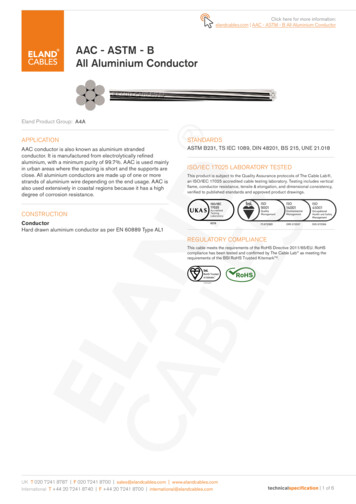
Extruded and welded members are never totally perfect. They possess a number ofimperfections. Residual stresses, heat-affected zones and other variation of materialproperties and the Baushinger effect are dealt with in section 1.06 and 1.07. Other types ofimperfections, for example initial curvature and deviation of cross sectional dimensions, aredealt with in section 1.05. The stress-strain relationship of aluminium is dealt with insection 1.08.It is of great importance to take the influence of imperfections into consideration, especiallyfor different types of instability phenomena, e.g. flexural buckling, lateral-torsionalbuckling and plate buckling. To illustrate this, consider the case of flexural buckling for abar subjected to an axial load, cf. Figure 2301.01.01. In the past, the compressive forcecapacity was calculated with Euler's buckling formula. This formula is valid for a perfectlystraight, elastic bar without imperfections. However, in reality, such a bar contains anumber of imperfections that reduce the strength. In Figure 2301.01.01 the behaviour of anidealised Euler column is compared to that of a real column.NNcrNInitiallystraight barδNBar with initial deflectionδaluTraining in Aluminium Application TechnologiesComparison between buckling behavior of an idealizedEuler bar and of a real bar with imperfections2301.01.01It is possible, in the age of computers, to create calculation models that can, with greatdetail, simulate the actual behaviour, but under one condition. Every imperfection of thebeam must be known and correctly modelled and taken into consideration. Residual stressesand variation in material properties have little influence on the behaviour of extrudedmembers. On the other hand, the first two of these imperfections can have great effect onwelded members.Welding effects the member by creating residual stresses and reduction in strength of thematerial in the heat affected zones.1.05Geometrical imperfectionsTALAT 23018
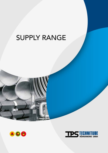
1.051 Extruded profilesInitial curvatureThe deviation of cross section dimensions and member length is often very small forextruded members. The effect is however not negligible if there is risk for instability, e.g.flexural buckling and lateral-torsional buckling.A systematic analysis carried out on extrusions from several European countries showedthat the initial curvature was approximately L/2000. In national specifications, initialcurvature is usually presumed to lie between L/500 and L/1000. It is common to use thesame value as for rolled steel sections. The ECCS (European Convention for ConstructionalSteelwork) recommends that v0 is taken as L/1000 when calculating buckling curves forextruded profiles, cf. Figure 2301.01.02. This value may seem to be far on the safe side.However, another geometrical imperfection is considered within this value; deviation ofsectional dimensions.Deviation of cross sectional dimensionsDeviation of width for sectional parts is usually lower than 1 percent. The thickness canvary 5 percent and for parts thinner than 5 mm the deviation can be up to 10 percent. Thethickness of hollow extrusions can have large variations. This is due to the extrusionprocess. Even a perfect die causes deviation of thickness in a hollow extrusion. This isenhanced in extrusions with small cross sections, cf. Figure 2301.01.02.The effect of this imperfection is that a centric compressive load actually has a certaineccentricity. The point of load introduction, in this case, does not coincide with the centreof gravity for the cross section.For extruded profiles and welded profiles, measurements show that this eccentricity, e, isless than L/1600. Together with the initial curvature of L/2000, this explains why initialcurvature in national regulations is considered to be less than L/1000.TALAT 23019
vPGrLrtmintmaxt (tmax - tmin)/2v1 L 1000alu t/t (tmax - t) / tDefinition of initial curvature and eccentricityTraining in Aluminium Application Technologies2301.01.02Initial bucklesFlat parts in extruded profiles show very small initial buckles. This is of two reasons; thefirst is that it is difficult to produce extrusions with sectional parts so slender that initialbuckles can develop. The second reason is that the traction process that follows extrusionreduces any initial buckles.1.052 Welded profilesThe influence of residual stresses and the strength reduction in the heat-affected zone, aredealt with in section 1.06 and 1.07. In this section, initial curvature and variation insectional dimensions are discussed.Measurement of welded T-sections and box sections show that the initial curvature isalways less than L/1300, i.e. always greater than for extruded profiles.The cross section measurement is within the same tolerance limits as for extruded profiles.One important imperfection on welded I-sections, where the web is welded directly to theflanges with fillet welds, is that the web plate often is a little eccentric. Measurements onsuch profiles showed eccentricities not greater than L/1600. Conclusively, this means thatthe same initial curvature can be used for welded profiles as for extruded profiles, whendetermining buckling curve, i.e. L/1000.Initial buckles in flat cross section elementsInitial buckles in welded beams (flanges and webs) cannot be avoided. The followingtolerances are recommended, if smaller tolerances are not necessary for aesthetic or otherTALAT 230110
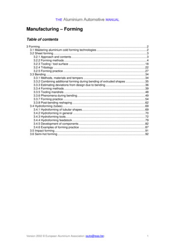
tfefreasons.ewLbtwbftwaluTolerated divergence from flatness of web and flanges2301.01.03Training in Aluminium Application TechnologiesTolerated buckles in the web are given in the following expressions. The limit is appliedto each panels of the web with horizontal stiffeners.bwbwhen w 50ew 200twew b 2wbwhen 50 w 12510000 t wtw(1.01)bwbwhen w 12580twThe largest tolerable deflections for an outstand element in compression, i.e. thecompression flange for an I- ,U- or Z- cross section, are given in the following expressions.bfLb 10whenef 250tf(1.02)bfLb b wwhen 10ef 2500 t ftfew 1.06Residual stresses and variability in material propertiesExtruded and welded profiles contain imperfections of different kinds. In this section,residual stresses, variability in material properties and the Bauschinger effect are dealt with.Other kinds of imperfections, e.g. initial curvature and variability in dimensions of the crosssection are dealt with in section 1.5.TALAT 230111
1.061 Residual stressesIf a part of a member undergoes nonuniform, plastic deformation stresses arise within theelastic area. The sum of negative and positive stresses is always zero, if there are noexternal forces. The inhomogeneous deformation field which generates residual stress iscaused by thermal processes such as cooling after extrusion and welding, mechanicalprocesses such as cold rolling and straightening by means of traction.For a welded T-profile the residual stresses may be formed as follows:The weld is very warm in the beginning. The zone next to the weld is also very warm.When the material cools down, the weld shrinks because of differences in density betweenthe hard and the soft material. Further, the weld will shrink because of the thermal diffusionfactor. The surrounding cold and stiff metal prevent this shrinking. This part of the crosssection is subject to compressive stresses while the area closest to the weld string is loadedwith tensile stresses. See Figure 2301.01.04. Weldsalu -Example of residual stresses in an welded T-profileTraining in Aluminium Application Technologies2301.01.04How to measure residual stressThe most common method is the destructive method, which is based upon the technique ofcutting the specimen in a number of strips. The residual stresses are calculated frommeasurements on each strip.There are two methods of measuring. The first is to measure the length of the strip beforeand after the cutting it from the section. If Young's modulus is known, it is easy to applyHooke's law and determine the residual stress. The second method is to mount electricalresistance strain gauges on the strips and determine the residual stresses by applyingHooke's law. The last method is that which is most commonly used today. Note thatHooke's law can be applied since residual stress is essentially an elastic process. With themethods stated here only longitudinal residual stresses are determined. However, these areof most interest from a structural point of view.TALAT 230112
Residual stress in extruded profilesMazzolani [see TALAT 2600] has shown results from a number of experiments whereresidual stresses are determined for different types of profiles. These consist of differentalloys and were manufactured by various processes.Here, the results from experiments on I-profiles are reviewed.Experiments conducted on I-profiles consisting of different alloys show that the residualstresses are randomly distributed over a cross section. It seems there is no simple rule forstress distribution as there is for rolled steel sections. Residual stresses are low, thecompressive stresses almost never exceed 20 MPa and tensile stresses are much lower.These values are measured on the surface of the profiles. At the centre of the material thevalues are probably lower since residual stresses usually change sign from one side to theother. Different alloys do not affect the intensity and distribution of residual stresses.The residual stresses have a negligible effect on the load-bearing capacity.Residual stresses in welded profilesIn contrast to what has been said for extruded profiles, residual stresses cannot be neglectedin welded profiles. The welding produces a concentrated heat input, which causes theremaining stresses (see above). Large tensile stresses in connection to the web andbalancing compression stresses in other parts are characteristic.Figure 2301.01.04 showed an example of the results of an experiment where twoaluminium plates were welded together with butt welds. The plates were of different sizes,and alloys. One was of a heat-treated alloy and one of a non heat-treated alloy. Thedifferences in the results were very small. The maximum tensile stress was 90 - 100 N/mm2and the maximum compression stress was 30 - 40 N/mm2. The lower values correspond tothe heat-treated alloy.TALAT 230113
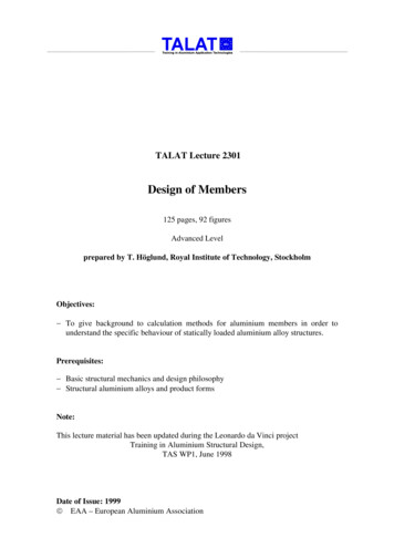
tensioncompression 40 MPa-Welds 25 MPa Welds90 MPa 120 MPaI-profile of flat platesaluI-profile of extruded T-flangesTypical residual stresses in welded I-profilesTraining in Aluminium Application Technologies2301.01.05Typical residual stress distributions for two different I-profiles are shown in Figure2301.01.05. The highest values of tensile stress were in both cases 140 N/mm2. The greatestvalue of compressive stress was 50 N/mm2 except for the web of the specimen to the rightin Figure 2301.01.05 where compressive stresses reached 100 N/mm2. One conclusion ofthese two experiments is that by welding together extruded profiles one can place the weldswithin the area where they cause a minimu
The design philosophy and the design procedure are discussed in Aluminium Design, part 4.1. In this chapter a short presentation of the partial coefficient method is given. Design values of strength of aluminium alloys are given in sub clause 2, Design basis. In all modern codes of practice structural safety is established by the application of the