Transcription
Introduction to Modern OpenGLProgrammingAdapted from SIGGRAPH 2012 slides byEd AngelUniversity of New MexicoandDave ShreinerARM, IncUniversity of Texas at AustinCS384G - Computer GraphicsFall 2010 Don Fussell
Outline Evolution of the OpenGL PipelineA Prototype Application in OpenGLOpenGL Shading Language (GLSL)Vertex ShadersFragment ShadersExamples
What Is OpenGL? OpenGL is a computer graphics rendering API With it, you can generate high-quality color imagesby rendering with geometric and image primitives It forms the basis of many interactive applicationsthat include 3D graphics By using OpenGL, the graphics part of yourapplication can be operating system independent window system independent
This is the “new” OpenGL We’ll concentrate on the latest versions of OpenGL They enforce a new way to program with OpenGL Allows more efficient use of GPU resources If you’re familiar with “classic” graphics pipelines,modern OpenGL doesn’t support Fixed-function graphics operations lighting transformations All applications must use shaders for their graphicsprocessing
The Evolution of the OpenGLPipelineUniversity of Texas at AustinCS384G - Computer GraphicsFall 2010 Don Fussell
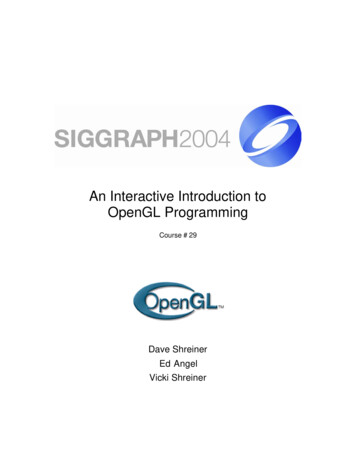
In the Beginning OpenGL 1.0 was released on July 1st, 1994 Its pipeline was entirely fixed-function the only operations available were fixed by theimplementationVertexDataVertexTransform andLightingPrimitiveSetup andRasterizationPixelDataFragmentColoring andTexturingBlendingTextureStore The pipeline evolved, but remained fixed-functionthrough OpenGL versions 1.1 through 2.0 (Sept. 2004)
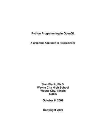
The Start of the Programmable Pipeline OpenGL 2.0 (officially) added programmable shaders vertex shading augmented the fixed-function transform andlighting stage fragment shading augmented the fragment coloring stage However, the fixed-function pipeline was still availableVertexDataVertexTransform andLightingPrimitiveSetup ing andTexturingBlending
An Evolutionary Change OpenGL 3.0 introduced the deprecation model the method used to remove features from OpenGL The pipeline remained the same until OpenGL 3.1(released March 24th, 2009) Introduced a change in how OpenGL contexts are usedContext TypeDescriptionFullIncludes all features (including those marked deprecated)available in the current version of OpenGLForward CompatibleIncludes all non-deprecated features (i.e., creates a contextthat would be similar to the next version of OpenGL)
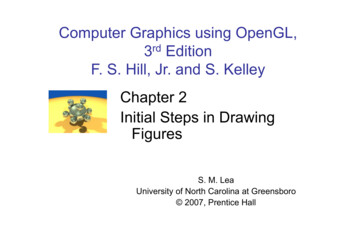
The Exclusively Programmable Pipeline OpenGL 3.1 removed the fixed-function pipeline programs were required to use only shadersVertexDataVertexShaderPrimitiveSetup tureStore Additionally, almost all data is GPU-resident all vertex data sent using buffer objects
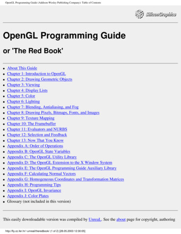
More Programmability OpenGL 3.2 (released August 3rd, 2009) added anadditional shading stage – geometry taTextureStorePrimitiveSetup andRasterizationFragmentShaderBlending
More Evolution – Context Profiles OpenGL 3.2 also introduced context profiles profiles control which features are exposed currently two types of profiles: core and compatibleContext TypeProfileDescriptioncoreAll features of the current releasecompatibleAll features ever in OpenGLcoreAll non-deprecated featurescompatibleNot supportedFullForward Compatible
The Latest Pipelines OpenGL 4.1 (released July 25th, 2010) includedadditional shading stages – tessellation-control andtessellation-evaluation shaders Latest version is 4.3VertexDataVertexShaderPrimitiveSetup aderFragmentShaderBlending
OpenGL ES and WebGL OpenGL ES 2.0 Designed for embedded and hand-held devices such as cellphones Based on OpenGL 3.1 Shader based WebGL JavaScript implementation of ES 2.0 Runs on most recent browsers
OpenGL ApplicationDevelopmentUniversity of Texas at AustinCS384G - Computer GraphicsFall 2010 Don Fussell
A Simplified Pipeline rtexShaderFramebufferGPU Data gmentShader
OpenGL Programming in a Nutshell Modern OpenGL programs essentially do thefollowing steps:1.2.3.4.Create shader programsCreate buffer objects and load data into them“Connect” data locations with shader variablesRender
Application Framework Requirements OpenGL applications need a place to render into usually an on-screen window Need to communicate with native windowingsystem Each windowing system interface is different We use GLUT (more specifically, freeglut) simple, open-source library that works everywhere handles all windowing operations: opening windows input processing
Simplifying Working with OpenGL Operating systems deal with library functionsdifferently compiler linkage and runtime libraries may exposedifferent functions Additionally, OpenGL has many versions andprofiles which expose different sets of functions managing function access is cumbersome, andwindow-system dependent We use another open-source library, GLEW, tohide those details
Representing Geometric Objects Geometric objects are represented using vertices A vertex is a collection of generic attributes positional coordinatescolorstexture coordinatesany other data associated with that point in space x y z w Position stored in 4 dimensional homogeneouscoordinates Vertex data must be stored in vertex buffer objects(VBOs) VBOs must be stored in vertex array objects(VAOs)
OpenGL’s Geometric Primitives All primitives are specified by verticesGL POINTSGL LINESGL LINE STRIPGL TRIANGLESGL LINE LOOPGL TRIANGLE FANGL TRIANGLE STRIP
A First ProgramUniversity of Texas at AustinCS384G - Computer GraphicsFall 2010 Don Fussell
Rendering a Cube We’ll render a cube with colors at each vertex Our example demonstrates: initializing vertex data organizing data for rendering simple object modeling building up 3D objects from geometric primitives building geometric primitives from vertices
Initializing the Cube’s Data We’ll build each cube face from individualtriangles Need to determine how much storage is required (6 faces)(2 triangles/face)(3 vertices/triangle)constintNumVertices 36; To simplify communicating with GLSL, we’ll use avec4 class (implemented in C ) similar to GLSL’svec4 type we’ll also typedef it to add logical meaningtypedefvec4point4;typedefvec4color4;
Initializing the Cube’s Data (cont’d) Before we can initialize our VBO, we need to stage thedata Our cube has two attributes per vertex position color We create two arrays to hold the VBO ices];
Cube gnedwithaxespoint4vertex positions[8] {point4(- ‐0.5,- ‐0.5,0.5,1.0),point4(- (0.5,- ‐0.5,0.5,1.0),point4(- ‐0.5,- ‐0.5,- ‐0.5,1.0),point4(- ‐0.5,0.5,- ‐0.5,1.0),point4(0.5,0.5,- ‐0.5,1.0),point4(0.5,- ‐0.5,- ‐0.5,1.0)};
Cube Data//RGBAcolorscolor4vertex colors[8] 0,1.0,1.0),//whitecolor4(0.0,1.0,1.0,1.0)//cyan};
Generating a Cube Face from Vertices// quad() generates two triangles for each face and assignscolors to the verticesint Index 0; // global variable indexing into VBO arraysvoid quad(int a, int b, int c, int d)colors[Index] vertex colors[a];vertex positions[a]; Index ;colors[Index] vertex colors[b];vertex positions[b]; Index ;colors[Index] vertex colors[c];vertex positions[c]; Index ;colors[Index] vertex colors[a];vertex positions[a]; Index ;colors[Index] vertex colors[c];vertex positions[c]; Index ;colors[Index] vertex colors[d];vertex positions[d]; Index ;}{points[Index] points[Index] points[Index] points[Index] points[Index] points[Index]
Generating the Cube from ,4,7);quad(6,5,1,2);quad(4,5,6,7);quad(5,4,0,1);}
Vertex Array Objects (VAOs) VAOs store the data of a geometric object Steps in using a VAO generate VAO names by callingglGenVertexArrays() bind a specific VAO for initialization by callingglBindVertexArray() update VBOs associated with this VAO bind VAO for use in rendering This approach allows a single function call tospecify all the data for an objects previously, you might have needed to make many callsto make all the data current
VAOs in xArrays(1,&vao);glBindVertexArray(vao);
Storing Vertex Attributes Vertex data must be stored in a VBO, andassociated with a VAO The code-flow is similar to configuring a VAO generate VBO names by calling glGenBuffers() bind a specific VBO for initialization by callingglBindBuffer(GL ARRAY BUFFER, ) load data into VBO usingglBufferData(GL ARRAY BUFFER, ) bind VAO for use in renderingglBindVertexArray()
VBOs in ;glGenBuffers(1,&buffer);glBindBuffer(GL ARRAY BUFFER,buffer);glBufferData(GL ARRAY BUFFER,sizeof(points) sizeof(colors),NULL,GL STATIC DRAW);glBufferSubData(GL ARRAY BUFFER,0,sizeof(points),points);glBufferSubData(GL ARRAY BUFFER,sizeof(points),sizeof(colors),colors);
Connecting Vertex Shaders with Geometry Application vertex data enters the OpenGLpipeline through the vertex shader Need to connect vertex data to shadervariables requires knowing the attribute location Attribute location can either be queried bycalling glGetVertexAttribLocation()
Vertex Array ntvPosition r(vPosition,4,GL FLOAT,GL FALSE,0,BUFFER OFFSET(0));GLuintvColor or,4,GL FLOAT,GL FALSE,0,BUFFER OFFSET(sizeof(points)));
Drawing Geometric Primitives For contiguous groups of verticesglDrawArrays(GL TRIANGLES,0,NumVertices); Usually invoked in display callback Initiates vertex shader
Shaders and GLSLUniversity of Texas at AustinCS384G - Computer GraphicsFall 2010 Don Fussell
GLSL Data TypesScalar types: float, int, boolVector types: vec2, vec3, vec4ivec2, ivec3, ivec4bvec2, bvec3, bvec4Matrix types: mat2, mat3, mat4Texture sampling: sampler1D, sampler2D, sampler3D,samplerCubeC style constructors: vec3 a vec3(1.0, 2.0, 3.0);
Operators Standard C/C arithmetic and logic operators Operators overloaded for matrix and vector operationsmat4m;vec4a,b,c;b a*m;c m*a;
Components and SwizzlingFor vectors can use [ ], xyzw, rgba or stpqExample:vec3v;v[1],v.y,v.g,v.tall refer to the same elementSwizzling:vec3a,b;a.xy b.yx;
Qualifiers in, out Copy vertex attributes and other variables to/fromshaders invec2tex coord; outvec4color; Uniform: variable from application uniformfloattime; uniformvec4rotation;
Flow Control if if else expression ? true-expression : falseexpression while, do while for
Functions Built in Arithmetic: sqrt, power, abs Trigonometric: sin, asin Graphical: length, reflect User defined
Built-in Variables gl Position: output position from vertexshader gl FragColor: output color from fragmentshader Only for ES, WebGL and older versions of GLSL Present version use an out variable
Simple Vertex Shader for main(){color vColor;gl Position vPosition;}
The Simplest Fragment Color color;}
Getting Shaders into OpenGL Shaders need to be compiledand linked to form anexecutable shader program OpenGL provides the compilerand linker A program must contain vertex and fragmentshaders other shaders are glCreateShader()Load Shader()Attach Shaderto se ProgramglUseProgram()Thesesteps needto berepeatedfor eachtype ofshader inthe shaderprogram
A Simpler Way We’ve created a routine for this course to make iteasier to load your shaders available at course *fFile); InitShaderstakes two filenames vFile for the vertex shader fFile for the fragment shader Fails if shaders don’t compile, or program doesn’tlink
Associating Shader Variables and Data Need to associate a shader variable with an OpenGL datasource vertex shader attributes app vertex attributes shader uniforms app provided uniform values OpenGL relates shader variables to indices for the app toset Two methods for determining variable/index association specify association before program linkage query association after program linkage
Determining Locations After LinkingAssumes you already know the variables’ nameGLint idx glGetAttribLocation(program, “name”);GLint idx glGetUniformLocation(program, “name”);
Initializing Uniform Variable ValuesUniform pose GL TRUE;//Sincewe’reCprogrammersGlfloatmat[3][4][4] { };glUniformMatrix4fv(index,3,transpose,mat);
Finishing the Cube argv);glutInitDisplayMode(GLUT RGBA GLUT DOUBLE GLUT );return0;}
Cube Program GLUT Callbacksvoiddisplay(void){glClear(GL COLOR BUFFER BIT GL DEPTH BUFFER BIT);glDrawArrays(GL 033:case'q':case'Q':exit(EXIT SUCCESS);break;}}
Vertex Shader Examples A vertex shader is initiated by each vertex output byglDrawArrays() A vertex shader must output a position in clipcoordinates to the rasterizer Basic uses of vertex shaders Transformations Lighting Moving vertex positions
Transformations
Camera Analogy3D is just like taking a photograph (lots ofphotographs!)viewingvolumecameratripodmodel
Transformations" Transformations take us from one “space” toanother" All of our transforms are 4 4 matricesModelingTransform"ModelingTransform"Object Coords.VertexDataModel-ViewTransform"World Coords.ProjectionTransform"Eye ormalizedClip Coords. DeviceCoords.2D WindowCoordinates
Camera Analogy Transform Sequence Modeling transformations assemble the world and move the objects Viewing transformations define position and orientation of the viewingvolume in the world Projection transformations adjust the lens of the camera Viewport transformations enlarge or reduce the physical photograph
3D Homogeneous Transformations A vertex istransformed by 4 4matrices all affine operationsare matrixmultiplications all matrices are storedcolumn-major inOpenGL this is opposite ofwhat “C”programmers expect matrices are alwayspost-multiplied product of matrix andvector is Mv m0 m1 M m2 m3m4m5m8m9m6 m10m7 m11m12 m13 m14 m15
View Specification Set up a viewing frustum to specify how muchof the world we can see Done in two steps specify the size of the frustum (projection transform) specify its location in space (model-view transform) Anything outside of the viewing frustum isclipped primitive is either modified or discarded (if entirelyoutside frustum)
View Specification (cont’d) OpenGL projection model uses eye coordinates the “eye” is located at the origin looking down the -z axis Projection matrices use a six-plane model: near (image) plane and far (infinite) plane both are distances from the eye (positive values) enclosing planes top & bottom, left & right
Viewing Transformations Position the camera/eye in the scene To “fly through” a scene change viewing transformation andredraw scene z) up vector determines unique orientation careful of degenerate positions
TranslationMove object or changeframe origin&1 0T (t x , t y , t z ) 0 0%00100100tx #!ty !!tz !!1 !"
ScaleStretch, mirror or decimate acoordinate direction& sx 0S (sx , s y , sz ) 0 0%00sy00sz000#!0!!0!!1 !"Note, there’s a translation applied here tomake things easier to see
RotationRotate coordinate system about an axis in spaceNote, there’s a translation appliedhere to make things easier to see
Vertex Shader for Cube n.vec3angles radians(theta);vec3c cos(angles);vec3s sin(angles);
Vertex Shader for Cube Rotation//Remember:thesematricesarecolumn- ‐majormat4rx mat4(1.0,0.0,0.0,0.0,0.0,c.x,s.x,0.0,0.0,- ‐s.x,c.x,0.0,0.0,0.0,0.0,1.0);mat4ry mat4(c.y,0.0,- ,0.0,1.0);
Vertex Shader for Cube Rotationmat4rz mat4(c.z,- ,0.0,0.0,1.0);color vColor;gl Position rz*ry*rx*vPosition;}
Sending Angles from isanglesvoiddisplay(void){glClear(GL COLOR BUFFER BIT GL DEPTH BUFFER BIT);glUniform3fv(theta,1,Theta);glDrawArrays(GL TRIANGLES,0,NumVertices);glutSwapBuffers();}
Vertex LightingUniversity of Texas at AustinCS384G - Computer GraphicsFall 2010 Don Fussell
Lighting Principles Lighting simulates how objects reflect light material composition of object light’s color and position global lighting parameters Lighting functions deprecated in 3.1 Can implement in Application (per vertex) Vertex or fragment shaders
Modified Phong Model Computes a color or shade for each vertex using alighting model (the modified Phong model) that takesinto account Diffuse reflections Specular reflections Ambient light Emission Vertex shades are interpolated across polygons by therasterizer
Modified Phong Model The model is a balance between simple computationand physical realism The model uses Light positions and intensitiesSurface orientation (normals)Material properties (reflectivity)Viewer location Computed for each source and each color component
OpenGL Lighting Modified Phong lighting model Computed at vertices Lighting contributors Surface material properties Light properties Lighting model properties
Surface Normals Normals define how a surface reflects light Application usually provides normals as a vertex atttribute Current normal is used to compute vertex’s color Use unit normals for proper lighting scaling affects a normal’s length
Material Properties Define the surface properties of a primitivePropertyDescriptionDiffuseBase object colorSpecularHighlight colorAmbientLow-light colorEmissionGlow colorShininessSurfacesmoothness you can have separate materials for front and back
Adding Lighting to ininess;
Adding Lighting to rdinatesvec3pos (ModelView*vPosition).xyz;vec3L normalize(LightPosition.xyz- ‐pos);vec3E normalize(- ‐pos);vec3H normalize(L E);//Transformvertexnormalintoeyecoordinatesvec3N normalize(ModelView*vec4(vNormal,0.0)).xyz;
Adding Lighting to ient AmbientProduct;floatKd max(dot(L,N),0.0);vec4diffuse Kd*DiffuseProduct;floatKs pow(max(dot(N,H),0.0),Shininess);vec4specular Ks*SpecularProduct;if(dot(L,N) 0.0)specular vec4(0.0,0.0,0.0,1.0)gl Position Projection*ModelView*vPosition;color ambient diffuse specular;color.a 1.0;}
Shader ExamplesUniversity of Texas at AustinCS384G - Computer GraphicsFall 2010 Don Fussell
Fragment Shaders A shader that’s executed for each “potential” pixel fragments still need to pass several tests before making it tothe framebuffer There are lots of effects we can do in fragment shaders Per-fragment lighting Bump Mapping Environment (Reflection) Maps
Per Fragment Lighting Compute lighting using same model as for pervertex lighting but for each fragment Normals and other attributes are sent to vertexshader and output to rasterizer Rasterizer interpolates and provides inputs forfragment shader
Shader Examples Vertex Shaders Moving vertices: height fields Per vertex lighting: height fields Per vertex lighting: cartoon shading Fragment Shaders Per vertex vs. per fragment lighting: cartoon shader Samplers: reflection Map Bump mapping
Height Fields A height field is a function y f(x, z) where they value represents a quantity such as the heightabove a point in the x-z plane. Heights fields are usually rendered by samplingthe function to form a rectangular mesh oftriangles or rectangles from the samples yij f(xi, zj)
Displaying a Height Field Form a quadrilateral meshfor(i 0;i N;i )for(j 0;j N;j )data[i][j] f(i,j,time);vertex[Index ] x ] vec3((float)i/N,data[i][j],(float)(j 1)/N);vertex[Index ] vec3((float)(i 1)/N,data[i][j],(float)(j 1)/N);vertex[Index ] vec3((float)(i 1)/N,data[i][j],(float)(j)/N); Display each quad usingfor(i 0;i NumVertices;i 4)glDrawArrays(GL LINE LOOP,4*i,4);
Time Varying Vertex nMatrix;voidmain(){vec4v vPosition;vec4t sin(0.001*time 5.0*v);v.y 0.1*t.x*t.z;gl Position ModelViewProjectionMatrix*t;}
Mesh Display
Adding Lighting Solid Mesh: create two triangles for eachquad Display withglDrawArrays(GL TRIANGLES,0,NumVertices); For better looking results, we’ll add lighting We’ll do per-vertex lighting leverage the vertex shader since we’ll also use it tovary the mesh in a time-varying way
Mesh ion,light positiondiffuse light,specular onMatrix,NormalMatrix;voidmain(){vec4v vPosition;vec4t sin(0.001*time 5.0*v);v.y 0.1*t.x*t.z;gl Position ec4eyePosition ModelViewMatrix*vPosition;vec4eyeLightPos light position;
Mesh Shader (cont’d)vec3N normalize(NormalMatrix*Normal);vec3L normalize(eyeLightPos.xyz- ‐eyePosition.xyz);vec3E - ‐normalize(eyePosition.xyz);vec3H normalize(L E);floatKd max(dot(L,N),0.0);floatKs pow(max(dot(N,H),0.0),shininess);diffuse Kd*diffuse light;specular Ks*specular light;color diffuse specular;}
Shaded Mesh
Texture MappingUniversity of Texas at AustinCS384G - Computer GraphicsFall 2010 Don Fussell
Texture Mappingyzxgeometrytimagesscreen
Texture Mapping in OpenGL Images and geometry flow through separatepipelines that join at the rasterizer “complex” textures do not affect zerPixelsPixelPipelineFragmentShader
Applying Textures Three basic steps to applying a texture1. specify the texture read or generate image assign to texture enable texturing2. assign texture coordinates to vertices3. specify texture parameters wrapping, filtering
Applying Textures1.2.3.4.5.6.7.8.specify textures in texture objectsset texture filterset texture functionset texture wrap modeset optional perspective correction hintbind texture objectenable texturingsupply texture coordinates for vertex
Texture Objects Have OpenGL store your images one image per texture object may be shared by several graphics contexts Generate texture namesglGenTextures(n,*texIds);
Texture Objects (cont'd.) Create texture objects with texture data andstate glBindTexture(target,id); Bind textures before using glBindTexture(target,id);
Specifying a Texture Image Define a texture image from an array oftexels in CPU der,format,type,*texels); Texel colors are processed by pixel pipeline pixel scales, biases and lookups can bedone
Mapping a Texture Based on parametric texture coordinates Coordinates need to be specified at each vertext0, 1Texture Space1, 1(s, t) (0.2, 0.8)Aab0, 0Object Spacec(0.4, 0.2)B1, 0sC(0.8, 0.4)
Applying the Texture in the Shader// Declare the sampleruniform sampler2D diffuse mat;// GLSL 3.30 has overloaded texture();// Apply the material colorvec3 diffuse intensity *texture2D(diffuse mat, coord).rgb;
Texturing the Cube// add texture coordinate attribute to quadfunctionquad(int a, int b, int c, int d) {quad colors[Index] vertex colors[a];points[Index] vertex positions[a];tex coords[Index] vec2(0.0, 0.0);Index ; // rest of vertices}
Creating a Texture Image// Create a checkerboard patternfor (int i 0; i 64; i ) {for (int j 0; j 64; j ) {GLubyte c;c (((i & 0x8) 0) ((j & 0x8) 0)) * 255;image[i][j][0] c;image[i][j][1] c;image[i][j][2] c;image2[i][j][0] c;image2[i][j][1] 0;image2[i][j][2] c;}}
Texture glBindTexture(GL TEXTURE 2D,textures[0]);glTexImage2D(GL TEXTURE 2D,0,GL RGB,TextureSize,TextureSize,GL RGB,GL UNSIGNED BYTE,image);glTexParameterf(GL TEXTURE 2D,GL TEXTURE WRAP S,GL REPEAT);glTexParameterf(GL TEXTURE 2D,GL TEXTURE WRAP T,GL REPEAT);glTexParameterf(GL TEXTURE 2D,GL TEXTURE MAG FILTER,GL NEAREST);glTexParameterf(GL TEXTURE 2D,GL TEXTURE MIN FILTER,GL NEAREST);glActiveTexture(GL TEXTURE0);
Vertex Shaderin vec4 vPosition;in vec4 vColor;in vec2 vTexCoord;out vec4 color;out vec2 texCoord;void main() {color vColor;texCoord vTexCoord;gl Position vPosition;}
Fragment Shaderin vec4 color;in vec2 texCoord;out vec4 FragColor;uniform sampler texture;void main() {FragColor color * texture(texture, texCoord);}
Next class: Visual Perception" Topic:How does the human visual system?How do humans perceive color?How do we represent color in computations?" Read: Glassner, Principles of Digital Image Synthesis,pp. 5-32. [Course reader pp.1-28] Watt , Chapter 15. Brian Wandell. Foundations of Vision. SinauerAssociates, Sunderland, MA, pp. 45-50 and69-97, 1995.[Course reader pp. 29-34 and pp. 35-63]University of Texas at AustinCS384G - Computer GraphicsFall 2010 Don Fussell106
OpenGL 2.0 (officially) added programmable shaders vertex shading augmented the fixed-function transform and lighting stage fragment shading augmented the fragment coloring stage However, the fixed-function pipeline was still available The Start of the Programmable Pipeline