Transcription
Power SystemsSAS RAID controllers for IBM i
Power SystemsSAS RAID controllers for IBM i
NoteBefore using this information and the product it supports, read the information in “Notices,” onpage 57, “Safety notices” on page v, the IBM Systems Safety Notices manual, G229-9054, and theIBM Environmental Notices and User Guide, Z125–5823.This edition applies to IBM Power Systems servers that contain the POWER6 processor and to all associatedmodels. Copyright International Business Machines Corporation 2009.US Government Users Restricted Rights – Use, duplication or disclosure restricted by GSA ADP Schedule Contractwith IBM Corp.
ContentsSafety notices . . . . . . . . . . . . . . . . . . . . . . . . . . . . . . . . . vChapter 1. What’s new in SAS RAID controllers for IBM i . . . . . . . . . . . . . . 1Chapter 2. SAS RAID controllers for IBM i . . . . . . . . . . . . . . . . . . . . . 3Feature comparison of SAS RAID cards . .PCI-X SAS RAID card comparison . . .PCIe SAS RAID card comparison . . .SAS architecture . . . . . . . . . .Disk arrays . . . . . . . . . . . .Supported RAID levels . . . . . .RAID 5 . . . . . . . . . . .RAID 6 . . . . . . . . . . .System mirroring . . . . . . .Disk array capacities . . . . . . .RAID level summary . . . . . . .Valid states for disk arrays and physical diskStates for disk arrays . . . . . . .States for disk units . . . . . . .Auxiliary write cache . . . . . . . .Auxiliary write cache adapter . . . .Viewing link status information . . .Chapter 3. Controller softwareVerifying the controller software. . . . . . .units. . . . . . 3. 3. 6. 8. 9. 10. 10. 11. 11. 11. 12. 12. 12. 13. 13. 14. 15. . . . . . . . . . . . . . . . . . . . . . . . . 17. 17Chapter 4. Common controller and disk array management tasks . . . . . . . . . . 19Viewing IBM SAS disk information .Considerations for solid-state drives . 19. 19Chapter 5. Dual storage IOA configurations . . . . . . . . . . . . . . . . . . . . 21Possible disk storage IOA configurationsDual storage IOA functions . . . . .Dual storage IOA function attributes . .Viewing dual storage IOA attributes . .SAS cabling considerations . . . . .Performance considerations . . . . .Dual storage IOA access optimization .Installing dual storage IOA configurations.2122242425262628Chapter 6. SAS RAID controller maintenance . . . . . . . . . . . . . . . . . . . 31Rechargeable battery maintenance . . . . . . . . . . . . . .Displaying rechargeable battery information . . . . . . . . .Error state . . . . . . . . . . . . . . . . . . . . .Forcing a rechargeable battery error . . . . . . . . . . . .Replacing a battery pack . . . . . . . . . . . . . . . . .Replacing a 572B nonconcurrent maintainable battery pack . . . .Replacing a 57B7 concurrent maintainable battery pack . . . . . .Replacing a 574E concurrent maintainable battery pack . . . . . .Replacing a 572F/575C card set concurrent maintainable battery pack .Separating the 572F/575C card set and moving the cache directory card .Viewing SAS fabric path information . . . . . . . . . . . . .Example: Using SAS fabric path information . . . . . . . . . . Copyright IBM Corp. 2009.313133343435373839404549iii
Chapter 7. SAS address and physical location information . . . . . . . . . . . . . 55Appendix. Notices . . . . . . . . . . . . . . . . . . . . . . . . . . . . . . . 57Trademarks . . . . .Electronic emission noticesClass A Notices . . .Terms and conditions . .iv.SAS RAID controllers for IBM i.58585862
Safety noticesSafety notices may be printed throughout this guide:v DANGER notices call attention to a situation that is potentially lethal or extremely hazardous topeople.v CAUTION notices call attention to a situation that is potentially hazardous to people because of someexisting condition.v Attention notices call attention to the possibility of damage to a program, device, system, or data.World Trade safety informationSeveral countries require the safety information contained in product publications to be presented in theirnational languages. If this requirement applies to your country, a safety information booklet is includedin the publications package shipped with the product. The booklet contains the safety information inyour national language with references to the U.S. English source. Before using a U.S. English publicationto install, operate, or service this product, you must first become familiar with the related safetyinformation in the booklet. You should also refer to the booklet any time you do not clearly understandany safety information in the U.S. English publications.German safety informationDas Produkt ist nicht für den Einsatz an Bildschirmarbeitsplätzen im Sinne § 2 derBildschirmarbeitsverordnung geeignet.Laser safety informationIBM servers can use I/O cards or features that are fiber-optic based and that utilize lasers or LEDs.Laser complianceAll lasers are certified in the U.S. to conform to the requirements of DHHS 21 CFR Subchapter J for class1 laser products. Outside the U.S., they are certified to be in compliance with IEC 60825 as a class 1 laserproduct. Consult the label on each part for laser certification numbers and approval information.CAUTION:This product might contain one or more of the following devices: CD-ROM drive, DVD-ROM drive,DVD-RAM drive, or laser module, which are Class 1 laser products. Note the following information:v Do not remove the covers. Removing the covers of the laser product could result in exposure tohazardous laser radiation. There are no serviceable parts inside the device.v Use of the controls or adjustments or performance of procedures other than those specified hereinmight result in hazardous radiation exposure.(C026)CAUTION:Data processing environments can contain equipment transmitting on system links with laser modulesthat operate at greater than Class 1 power levels. For this reason, never look into the end of an opticalfiber cable or open receptacle. (C027)CAUTION:This product contains a Class 1M laser. Do not view directly with optical instruments. (C028) Copyright IBM Corp. 2009v
CAUTION:Some laser products contain an embedded Class 3A or Class 3B laser diode. Note the followinginformation: laser radiation when open. Do not stare into the beam, do not view directly with opticalinstruments, and avoid direct exposure to the beam. (C030)Power and cabling information for NEBS (Network Equipment-Building System)GR-1089-COREThe following comments apply to the IBM servers that have been designated as conforming to NEBS(Network Equipment-Building System) GR-1089-CORE:The equipment is suitable for installation in the following:v Network telecommunications facilitiesv Locations where the NEC (National Electrical Code) appliesThe intrabuilding ports of this equipment are suitable for connection to intrabuilding or unexposedwiring or cabling only. The intrabuilding ports of this equipment must not be metallically connected to theinterfaces that connect to the OSP (outside plant) or its wiring. These interfaces are designed for use asintrabuilding interfaces only (Type 2 or Type 4 ports as described in GR-1089-CORE) and require isolationfrom the exposed OSP cabling. The addition of primary protectors is not sufficient protection to connectthese interfaces metallically to OSP wiring.Note: All Ethernet cables must be shielded and grounded at both ends.The ac-powered system does not require the use of an external surge protection device (SPD).The dc-powered system employs an isolated DC return (DC-I) design. The DC battery return terminalshall not be connected to the chassis or frame ground.viSAS RAID controllers for IBM i
Chapter 1. What’s new in SAS RAID controllers for IBM iThis topic collection is new for the October 2009 release. Copyright IBM Corp. 20091
2SAS RAID controllers for IBM i
Chapter 2. SAS RAID controllers for IBM iFind usage and maintenance information regarding controllers for the serial-attached SCSI (SAS)Redundant Array of Independent Disks (RAID) for IBM i. Use this information with your specific systemunit and operating system documentation. General information is intended for all users of this product.Service information is intended for a service representative trained on the system unit and the subsystembeing serviced.The SAS RAID controllers for IBM i have the following features:v PCI-X 266 system interface or PCI Express (PCIe) system interface.v Physical link speed of 3 Gbps SAS that supports transfer rates of 300 MB per second.v Support for SAS devices and nondisk Serial Advanced Technology Attachment (SATA) devices.v Optimized for SAS disk configurations that use dual paths through dual expanders for redundancyand reliability.v Controller managed path redundancy and path switching for multiported SAS devices.v Embedded PowerPC Reduced Instruction Set Computer (RISC) processor, hardware XOR DirectMemory Access engine, and hardware finite field multiplier (FFM) DMA engine for RAID 6.v Some adapters that support nonvolatile write cache.v Support for RAID 5 and RAID 6 disk arrays and system mirroring.v Supports attachment of other devices such as non-RAID disks, tape, and optical devices.v RAID disk arrays and non-RAID devices supported as a bootable device.v Advanced RAID features:– Hot spares for RAID 5 and 6 disk arrays and system mirroring.– Ability to increase the capacity of an existing RAID 5 or 6 disk array by adding disks.– Background parity checking.– Background data scrubbing.– Disks formatted to 528 bytes per sector, providing cyclical redundancy checking (CRC) and logicallybad-block checking.– Optimized hardware for RAID 5 and 6 sequential write workloads.– Optimized skip read-and-write disk support for transaction workloads.v Supports a maximum of 64 advanced function disks with a maximum of 255 devices.Note: The number of all physical SAS and SATA devices plus the number of logical RAID disk arraysmust be less than 255 per controller.Feature comparison of SAS RAID cardsCompare the main features of PCI-X and PCI Express (PCIe) SAS RAID cards for IBM i.The tables in this section provide a breakdown of the main features of the SAS RAID PCI-X and PCIecontroller cards.PCI-X SAS RAID card comparisonUse the table in this topic to compare the features of PCI-X SAS RAID cards for IBM i. There are alsoimages of adapters for you to view. Copyright IBM Corp. 20093
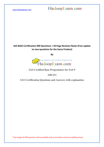
Table 1. PCI-X SAS RAID controller card comparisonFeatures572A572C572F and 575C57B8DescriptionPCI-X 266 ExtDual-x4 3 Gb SASadapterPCI-X 266 planar 3Gb SAS adapterPCI-X 266 Ext Tri-x4 3 PCI-X 266 planar 3Gb SAS RAIDGb SAS RAIDadapteradapterForm factorLow profile 64 bitPCI-XPlanar integratedLong 64 bit PCI-X,double-wide card setPlanar RAIDenablementPhysical links8 (two mini SAS 4xconnectors)8112 (bottom 3 miniSAS 4x connectors)and 2 (top mini SAS4x connector for highavailability only)81RAID levelssupportedRAID 53, RAID 63,system mirroringSystem mirroringRAID 5, RAID 6,system mirroringRAID 5, RAID 6,system mirroringWrite cache sizeUp to 1.5 Gb(compressed)175 MBRead cache sizeUp to 1.6 Gb(compressed)Cache battery packtechnologyLithium ionNot applicable2Cache batteryconcurrentmaintenanceNoNoYes4Not applicable2Cache data presentLEDNoNoNoNoRemovable cache card NoNoNoNoAuxiliary write cache(AWC) supportNoNoYesYesDual storage IOAconfigurationNoNoYesNoRequires dual storage NoIOA configurationNoNoNo1. Some systems provide an external mini SAS 4x connector from the integrated backplane controller.2. The controller contains battery-backed cache, but the battery power is supplied by the 57B7 controller throughthe backplane connections.3. The write performance of RAID 5 and RAID 6 might be poor on adapters that do not provide write cache.Consider using an adapter that provides write cache when using RAID 5 or RAID 6.4. The cache battery pack for both adapters is contained in a single battery field-replaceable Unit (FRU), which isphysically located on the 575C Auxiliary Cache card.Adapter graphicsView the SAS RAID controllers.4SAS RAID controllers for IBM i
Figure 1. CCIN 572A PCI-X266 External Dual-x4 3 Gb SAS adapterFigure 2. CCIN 57B8 planar RAID enablement cardChapter 2. SAS RAID controllers for IBM i5
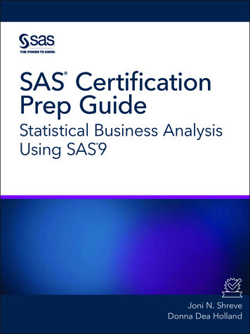
Figure 3. CCIN 572F PCI-X266 Ext Tri-x4 3 Gb SAS RAID adapter and CCIN 575C PCI-X266 Auxiliary Cache adapterRelated conceptsChapter 5, “Dual storage IOA configurations,” on page 21You can increase availability using a dual storage I/O adapter (IOA) configuration to connect multiplecontrollers to a common set of disk expansion drawers and the included disks and disk arrays.“Dual storage IOA functions” on page 22Consider these factors when using dual storage I/O adapter (IOA) functions.PCIe SAS RAID card comparisonUse the table in this topic to compare the features of a PCI Express (PCIe) SAS RAID cards for IBM i.There are also images of adapters for you to view.Table 2. PCIe SAS RAID controller card comparisonFeatures57B757B3574EDescriptionPCIe x1 Auxiliary CacheadapterPCIe x8 Ext Dual-x4 3 GbSAS adapterPCIe x8 Ext Dual-x4 3 GbSAS RAID adapterForm factorPlanar Auxiliary CachePCIe x8PCIe x8Physical links28 (two mini SAS 4xconnectors)8 (two mini SAS 4xconnectors)RAID 51, RAID 61, systemmirroringRAID 5, RAID 6, systemmirroringRAID levels supportedWrite cache size175 MB380 MBCache battery packtechnologyLithium ionLithium ionCache battery concurrentmaintenanceYesNoYesCache data present LEDYesNoYesRemovable cache cardNoNoYesRead cache size6SAS RAID controllers for IBM i
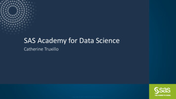
Table 2. PCIe SAS RAID controller card comparison (continued)Features57B757B3574EAuxiliary write cache(AWC) supportYesNoNoDual storage IOAconfigurationNoNoYesRequires dual storage IOAconfigurationNoNoYes1. The write performance of RAID 5 and RAID 6 might be poor on adapters that do not provide write cache.Consider using an adapter that provides write cache when using RAID 5 or RAID 6.Adapter graphicsView the SAS RAID controllers.Figure 4. CCIN 57B7 Planar Auxiliary CacheFigure 5. CCIN 57B3 PCIe x8 Ext Dual-x4 3 Gb SAS adapterChapter 2. SAS RAID controllers for IBM i7
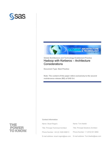
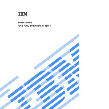
Figure 6. CCIN 574E PCIe x8 Ext Dual-x4 3 Gb SAS RAID adapterRelated conceptsChapter 5, “Dual storage IOA configurations,” on page 21You can increase availability using a dual storage I/O adapter (IOA) configuration to connect multiplecontrollers to a common set of disk expansion drawers and the included disks and disk arrays.“Dual storage IOA functions” on page 22Consider these factors when using dual storage I/O adapter (IOA) functions.SAS architectureSerial-attached SCSI (SAS) architecture defines a serial device interconnect and transport protocol thatdefines the rules for information exchange between devices.SAS is an evolution of the parallel SCSI device interface into a serial point-to-point interface. SASphysical links (phys) are a set of four wires used as two differential signal pairs. One differential signaltransmits in one direction, while the other differential signal transmits in the opposite direction. Data canbe transmitted in both directions simultaneously. Phys are contained in SAS ports which contain one ormore phys. A port is a wide port if there are more than one phy in the port. If there is only one phy inthe port, it is a narrow port. A port is identified by a unique SAS worldwide name (also called SASaddress).A SAS controller contains one or more SAS ports. A path is a logical point-to-point link between a SASinitiator port in the controller and a SAS target port in the I/O device (for example a disk). A connectionis a temporary association between a controller and an I/O device through a path. A connection enablescommunication to a device. The controller can communicate to the I/O device over this connection byusing either the SCSI command set or the ATA/ATAPI command set depending on the device type.A SAS expander enables connections between a controller port and multiple I/O device ports by routingconnections between the expander ports. Only a single connection through an expander can exist at any8SAS RAID controllers for IBM i
given time. Using expanders creates more nodes in the path from the controller to the I/O device. If anI/O device supports multiple ports, more than one path to the device can exist when there are expanderdevices included in the path.A SAS fabric refers to the summation of all paths between all SAS controller ports and all I/O deviceports in the SAS subsystem including cables, enclosures, and expanders.The following example SAS subsystem shows some of the concepts described in this SAS overview. Acontroller is shown with eight SAS phys. Four of those phys are connected into two different wide ports.One connector contains four phys grouped into two ports. The connectors have no significance in SASother than causing a physical wire connection. The four-phy connector can contain between one and fourports depending on the type of cabling that is used. The uppermost port in the figure shows acontroller-wide port number 6 that consists of phy numbers 6 and 7. Port 6 connects to an expander,which attaches to one of the dual ports of the I/O devices. The dashed red line indicates a path betweenthe controller and an I/O device. Another path runs from the controller’s port number 4 to the other portof the I/O device. These two paths provide two different possible connections for increased reliability byusing redundant controller ports, expanders, and I/O device ports. The SCSI Enclosure Services (SES) is acomponent of each expander.Figure 7. Example SAS SubsystemDisk arraysDisk arrays are groups of disks that work together with a specialized array controller to take advantage ofpotentially higher data transfer rates and data redundancy.Disk arrays use RAID technology to offer data redundancy and to provide improved data transfer ratesover single large disks. If a disk failure occurs, the disk can typically be replaced without interruptingnormal system operation.Data redundancyThe disk array controller tracks how the data is distributed across the disks. RAID 5 and RAID 6 diskarrays provide data redundancy, ensuring that data is not lost if a disk in the array fails. If a disk failureoccurs, the disk can typically be replaced without interrupting normal system operations. Systemmirroring provides data redundancy by mirroring the same data across pairs of disks.Chapter 2. SAS RAID controllers for IBM i9
Supported RAID levelsThe RAID level of a disk array determines how data is stored on the disk array and the level ofprotection that is provided.If a part of the RAID system fails, different RAID levels help to recover lost data in different ways. If asingle drive fails within an array, the array controller can reconstruct the data for the failed disk by usingthe data stored on other hard drives within the array. This data reconstruction has little or no impact tocurrent system programs and users. The controller supports RAID levels 5 and 6 as well as systemmirroring. Not all controllers support all RAID levels. Each RAID level supported by the controller has itsown attributes and uses a different method of writing data. The following information provides detailsfor each supported RAID level.Related concepts“PCI-X SAS RAID card comparison” on page 3Use the table in this topic to compare the features of PCI-X SAS RAID cards for IBM i. There are alsoimages of adapters for you to view.“PCIe SAS RAID card comparison” on page 6Use the table in this topic to compare the features of a PCI Express (PCIe) SAS RAID cards for IBM i.There are also images of adapters for you to view.Related informationDevice parity protection conceptsRAID 5Learn how data is written to a RAID 5 array.RAID 5 stripes data across all disks in the array. RAID level 5 also writes array parity data. The paritydata is spread across all the disks. For a RAID 5 array of three disks, array data and parity informationare written in the following pattern:Figure 8. RAID 5If a disk fails in a RAID 5 array, you can continue to use the array normally. A RAID 5 array operatingwith a single Failed disk is said to be operating in Degraded mode. Whenever data is read from aDegraded disk array, the array controller recalculates the data on the Failed disk by using data and parityblocks on the operational disks. If a second disk fails, the array will be placed in the Failed state and willnot be accessible.10SAS RAID controllers for IBM i
Related informationRAID 5 conceptsRAID 6Learn how data is written to a RAID 6 array.RAID 6 stripes data across all disks in the array. RAID level 6 also writes array ″P″ and ″Q″ parity data.The P and Q parity data, is spread across all the disks. For a RAID 6 array of four disks, array data andparity information are written in the following pattern:Figure 9. RAID 6If one or two disks fail in a RAID 6 array, you can continue to use the array normally. A RAID 6 arrayoperating with a one or two Failed disks is said to be operating in Degraded mode. Whenever data isread from a Degraded disk array, the array controller recalculates the data on the failed disks by usingdata and parity blocks on the operational disks. A RAID 6 array with a single failed disk has similarprotection to that of a RAID 5 array with no disk failures. If a third disk fails, the array will be placed inthe Failed state and will not be accessible.Related informationRAID 6 conceptsSystem mirroringMirrored protection is beneficial if you have a multibus system or a system with a large single bus. Agreater number of disk units provides more opportunity for failure and increased recovery time.Refer to Mirrored protection for more information.Disk array capacitiesThese guidelines will help you calculate the capacity of a disk array.The capacity of a disk array depends on the capacity of the disks used and the RAID level of the array.To calculate the capacity of a disk array, do the following:RAID 5Multiply one fewer than the number of disks by the disk capacity.Chapter 2. SAS RAID controllers for IBM i11
RAID 6Multiply two fewer than the number of disks by the disk capacity.System mirroringMultiply the number of disks by the disk capacity and divide by two.Note: If disks of different capacities are used in the same disk array, all disks are treated as if they havethe capacity of the smallest disk.RAID level summaryCompare RAID levels according to their capabilities.The following information provides data redundancy, usable disk capacity, read performance, and writeperformance for each RAID level.Table 3. RAID level summaryRAID levelUsable diskData redundancy capacityReadperformanceWriteperformanceDevices per arrayRAID 5Very goodVery goodGoodMinimum: 367% - 94%Maximum: 18RAID 6Excellent50% - 89%Very goodFair to goodMinimum: 4Maximum: 18System mirroringExcellent50%ExcellentVery goodNot applicableRAID 5Creates array parity information so that the data can be reconstructed if a disk in the array fails.Provides better capacity than System Mirroring but possibly lower performance.RAID 6Creates array ″P″ and ″Q″ parity information so that the data can be reconstructed if one or twodisks in the array fail. Provides better data redundancy than RAID 5 but with slightly lowercapacity and possibly lower performance. Provides better capacity than System Mirroring butpossibly lower performance.System MirroringStores data redundantly on mirrored pairs to provide maximum protection against disk failures.Provides generally better performance than RAID 5 or 6, but has lower capacity.Valid states for disk arrays and physical disk unitsDisk arrays and physical disks have several operational states.States for disk arraysThere are four valid states for disk arrays.View disk arrays by completing the following steps:1. Select Work with disk units on the Use System Service Tools (SST) menu.2. Select Display disk configuration from the Work with Disk Configuration display.3. Select Display device parity status on the Display Disk Configuration display.The valid four states for IBM SAS Disk Arrays are RAID 5, RAID 6, RAID 5/Availability, and RAID6/Availability.12SAS RAID controllers for IBM i
RAID 5Indicates that this parity set is configured as a RAID 5 parity set. If any one unit in the set shouldfail, the other units in the set would be able to sustain the functions of the failed unit. RAID 5requires one drive’s worth of capacity per array to hold the parity data.RAID 6Indicates that this parity set is configured as a RAID 6 parity set. If one or two units in the setshould fail, the other units in the set would be able to sustain the functions of the failed units.RAID 6 requires two drives’ worth of capacity per array to hold the parity data. If one unit in aRAID 6 parity set should fail, the parity set would have protection equivalent to a RAID 5 parityset.RAID 5/AvailabilityIndicates that this parity set is configured as a RAID 5 parity set which is optimized forAvailability. There is at most one disk per I/O bus.RAID 6/AvailabilityIndicates that this parity set is configured as a RAID 6 parity set which is optimized forAvailability. There are at most two disks per I/O bus.States for disk unitsThere are seven valid states for physical disk units.View disk arrays by completing the following steps.1. Select Work with disk units on the Use System Service Tools (SST) menu.2. Select Display disk configuration from the Work with Disk Configuration display.3. Select Display device parity status on the Display Disk Configuration display.The valid states for disk units are Active, Read/Write Protected, Failed, Rebuilt/Rebuilding, Unprotected,Power Loss, and Unknown.Active The disk is functioning correctly.Read/Write ProtectedThe disk is unavailable because of a hardware or a configuration problem.Failed The controller cannot communicate with the disk unit, or the disk unit the cause of the disk arraybeing in a Degraded (exposed) state.Rebuilt/RebuildingThe data on one of the units in the parity set is being rebuilt from other units in the set. All theunits in the set will have this status. Some subsystems will report their progress to the system. Ifthey do, it will be displayed in the status field. If another unit in the disk unit subsystem fails,data could be lost.UnprotectedThis unit is operational. However, another unit in the disk unit subsystem has failed. If anotherunit in the disk unit subsystem fails, data could be lost.Power LossThis unit has lost power. The unit was previously connected to the controller but is no longerdetected.UnknownThe state of the disk could not be determined.Auxiliary write cacheA duplicate, nonvolatile copy of write cache data can be preserved.Chapter 2. SAS RAID controllers for IBM i13
Auxiliary write cache adapterThe Auxiliary Write Cache (AWC) adapter provides a duplicate, nonvolatile copy of write cache data ofthe RAID controller to which it is connected.Protection of data is enhanced by having two battery-backed (nonvolatile) copies of write cache, eachstored on separate adapters. If a failure occurs to the write cache portion of the RAID controller, or theRAID controller itself fails in such a way that the write cache data is not recoverable, the AWC adapterprovides a backup copy of the write cache data to prevent data loss during the recovery of the failedRAID controller. The cache data is recovered to the new replacement RAID controller and then writtenout to disk before resuming normal operations.The AWC adapter is not a failover device that can keep the system operational by continuing diskoperations when the attached RAID controller fails. The system cannot use the auxiliary copy of thecache for runtime operations even if only the cache on the RAID controller fails. The AWC adapter doesnot support any other device attachment and performs no other tasks than communicating with theattached RAID controller to receive backup write cache data. The purpose of the AWC adapter is tominimize the length of an unplanned outage, due to a failure of a RAID controller, by preventing loss ofcritical data that might have otherwise required a system reload.It is important to understand the difference between dual storage IOA connections and AWC connections.Connecting controllers in a dual storage IOA environment refers to multiple RAID controllers connectedto a common set of disk enclosures and disks. The AWC controller is not connected to the disks, and itdoes not perform device media accesses.Important: If a failure of either the RAID controller or the Auxiliary Cache occurs, the Isolation andRecovery procedures for the System Reference Codes (SRCs) in the Service Action Log (SAL) or ProductActivity Log (PAL) must be followed precisely.The RAID controller and the AWC adapter each require a PCI bus connection and are required to be inthe same partition. The two adapters are connected by an internal SAS connection. For the Planar RAIDEnablement and Planar Auxiliary Cache features, the dedicated SAS connection is integrated into thesystem planar.If the AWC adapter itsel
The SAS RAID controllers for IBM i have the following features: v PCI-X 266 system interface or PCI Express (PCIe) system interface. v Physical link speed of 3 Gbps SAS that supports transfer rates of 300 MB per second. v Support for SAS devices and nondisk Serial Advanced Technology Attachment (SATA) devices.