Transcription
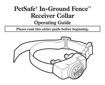
PetSafeIn-Ground Fence Operating and Training GuidePlease read this entire guide before beginning.ARFYERTTBA676V
Thank you for choosing PetSafe , the best selling brand of electronic training solutions in the world.Our mission is to be the most trusted brand in the pet ownership experience. We want to ensure yourpet’s safety by providing you with the tools and techniques to successfully train your pet. If you haveany questions, please contact the Customer Care Center at 1-800-732-2677 or visit our website atwww.petsafe.net.To get the most protection out of your warranty, please register your product within 30 days at www.petsafe.net. By registering and keeping your receipt, you will enjoy the product’s full warranty andshould you ever need to call the Customer Care Center, we will be able to help you faster. Mostimportantly, PetSafe will never give or sell your valuable information to anyone. Complete warrantyinformation is available online at www.petsafe.net.Table of ContentsComponents . 3Other Items You May Need . 3How the System Works . 4Key Definitions . 4Operating GuideLocate the Fence Transmitter . 5Lay Out the System . 5Sample Layouts . 6Position the Boundary Wire . 7Connect the Wires to the Fence Transmitter . 8Prepare the Receiver Collar. 8Set the Boundary Width and Test the Receiver Collar . 9Install the Boundary Wire .10Place the Boundary Flags .11Fit the Receiver Collar .11Training GuideBe Patient With Your Pet .13Days 1 and 2 - Boundary Flag Awareness .13Days 3 and 4 - Continue Boundary Flag Awareness .14Days 5 thru 8 - Distraction Phase .14Days 9 thru 14 - Unleashed Supervision.14Days 15 thru 30 - Pet Monitoring .15Taking Your Pet Out of the Pet Area .15Accessories .15Troubleshooting .16Short Loop Test .17To Locate a Break in the Wire .17Terms of Use and Limitation of Liability .18Compliance .18Customer Care International .18Caution .19Layout Grid .20Mounting Template .2021-800-732-2677
ComponentsFenceTransmitterBoundary Wire - 500 ft.PowerAdapterWire NutsBoundary Flags - 50ReceiverCollarGel-filledCapsulesTest LightToolBattery(PetSafe RFA-67) Operating andTraining GuideOther Items You May Need Additional wire and flags (Part #PRFA-500) Tape measure Small Phillips screwdriver Drill & mounting hardware Shovel or lawn edger Pliers Wire stripping pliers Scissors Lighter Electrical tape Gel-filled Capsules Additional wire nuts Waterproofing compound (e.g. silicone caulk) PVC pipe or water hose Circular saw with masonry blade Staple gun Non-metallic collar and leashFence installation and training help, interactive fence planning software: www.petsafe.net/fencewww.petsafe.net3
How the System WorksA radio signal travels from the Fence Transmitter through a buried wire, marking the boundaries you wish to set for yourdog. Your dog wears a Receiver Collar that detects the signal at the boundary. As your dog approaches the boundary, thereceiver issues a warning tone. If he proceeds further, he receives a safe but startling Static Correction. While harmless, thecorrection will persuade him to stay in the containment area you’ve established. Boundary flags are a temporary visual aidfor your pet; remove them after training. This PetSafe In-Ground Fence has been proven safe, comfortable, and effectivefor pets over 8 pounds.Key DefinitionsFence Transmitter: Transmits the radio signal through the Boundary Wire.Pet Area: Area within the Warning Zone where your pet can roam freely.Warning Zone: Outer edge of the Pet Area where your pet’s Receiver Collar begins to beep, warning him not to go into theStatic Correction Zone.Static Correction Zone: Zone beyond the Warning Zone where your pet’s Receiver Collar will emit a Static Correction,signaling him to return to the Pet Area.Boundary Width: Combination of the Warning Zone and the Static Correction Zone.Receiver Collar: Receives the radio signal from the Boundary Wire.Contact Points: Delivers the safe Static Correction when your pet moves into the Static Correction Zone.Power Jack: Where the Power Adapter plugs into the Fence Transmitter. The Fence Transmitter is powered by a standard120-volt outlet.Boundary Control Switch: Switch located on the Fence Transmitter to adjust according to the length of Boundary Wire used.Boundary Wire Terminals: Where the Boundary Wires connect to the Fence Transmitter in order to complete acontinuous loop.Loop Indicator Light: Indicates that the Boundary Wire makes a complete loop, enabling the signal to be transmitted.Boundary Width Control: Adjusts the width of the Warning and Static Correction Zones. Note: Adjusting the knob does notchange the level of Static Correction on the Receiver Collar.Fence TransmitterReceiver CollarFenceTransmitterStatic CorrectionZonePet olSwitchWire}BoundaryTerminalsStatic CorrectionZoneLoop Indicator LightBoundaryWidthWarningZoneWashersContact PointsPowerJackPower LightBoundary WidthControlWant professional installation help? Invisible Fence Brand installers will come to your home and install your newPetSafe System for an additional cost. Contact your local dealer at 1-877-866-DOGS (3647) or visit our website atwww.invisiblefence.com for more information.41-800-732-2677
Operating GuideStep1Locate the Fence TransmitterPlace the Fence Transmitter: In a dry, well ventilated, protected area (1A, 1B). In an area where temperatures do not fall below freezing (e.g., garage, basement, shed, closet). Secured to a stationary surface using appropriate mounting hardware (not included). A mounting template isincluded in the back of this guide. At least 3 feet from large metal objects or appliances as these items may interfere with the signal consistency (1C).Once you have mounted the Fence Transmitter, the Boundary Wire must exit the building. This can beaccomplished via a window or through a hole drilled through the wall. Ensure the drill path is clear of any utilities.Make sure the Boundary Wire is not cut off or pinched by a window, door, or garage door, as this can damage itover time.To prevent fires and electrical hazards, install the Fence Transmitter in buildings that are in accordance with stateand local electrical codes.1A1B1C3ft.Step2Lay Out the SystemBasic Planning TipsWarning: Before digging to bury the Boundary Wire of your In-Ground Fence , make sure that thereare no buried power, telephone, or other electrical cables in the vicinity. Many underground cablescarry high voltage and digging into them, or laying your Boundary Wire on them, may lead to hazardfrom shock or electrocution. Have the local utility company mark your underground lines. In mostcommunities this is a free service. For information regarding how these underground wires can affectyour system’s operation, see Step 3 Position the Boundary Wire. The Boundary Wire MUST start at2A2Bthe Fence Transmitter and make acontinuous loop back (2A). Twisting the Boundary Wire cancels thesignal and allows your pet to cross overthat area without correction. Plastic or10 Twists/ft.metal piping will not cancel the signal.Twist the Boundary Wire 10 to 12 timesper foot to cancel the signal (2A). Design a layout that is suitable for youryard. Sample layouts are provided inthis section, and a grid for designingyour layout is provided in the back ofthis guide. Fence planning software is availableonline at www.petsafe.net/fence. Always use gradual turns at the corners with a minimum of 3 foot radius to produce a more consistentboundary (2B). Do not use sharp turns, as this will cause gaps in your boundary. Avoid making passageways too narrow for your pet to move about freely (e.g., along the sides of a house). The Receiver Collar can be activated inside the house if the Boundary Wire runs along the outside wall of thehouse. If this occurs, remove your pet’s Receiver Collar before bringing him inside, decrease the range using theBoundary Width Control knob or consider an alternative layout.www.petsafe.net5
Sample LayoutsSample 1:Perimeter Loop(Single Loop)The PerimeterLoop is themost commonlayout. This willallow your pet tofreely and safelyroam your entireproperty (2C). Itcan also protectgardens, pools andlandscaping (2D).CBDAESample 2 (2E): Perimeter Loop Using ExistingFence (Single Loop)This layout allows you to include your existing fenceas part of your layout and keep your pet from jumpingout or digging under your existing fence. It reduces theamount of wire which will need to be buried. From theFence Transmitter, run the wire to A, A to B, B to C, Cto D, D to E, E to A, twist the wires from A back to theFence Transmitter. See the “Install the Boundary Wire”section for more information on attaching the wire to afence.Double LoopA Double Loop must be used when you are not establishing the Boundary Zone on all sides of your property.When using a Double Loop, the Boundary Wire must be separated by a minimum of 3 TO 5 FEET to avoidcanceling the signal. Remember that a Double Loop will require twice as much wire.DECFBEAFBEBAB3-5'DADA3-5'CCSample 3 (2F): Front or BackYard Only (Double Loop)From the Fence Transmitter, runthe wire to A, A to B, B to C, Cto D, D to E, E to F, make aU-turn and follow your path allthe way back to A, keeping thewire separated 3 to 5 feet. Twistthe wire from A back to theFence Transmitter.6Sample 4 (2G): FrontBoundary Only(Double Loop)From the Fence Transmitter,run the wire to A, A to B, Bback to A keeping the wireseparated 3 to 5 feet. Twistthe wire from A back to theFence Transmitter.1-800-732-2677Sample 5 (2H): Lake Access(Double Loop)From the Fence Transmitter,run the wire to A, A to B,make a U-turn and go to C, Cto D, D to E, make a U-turnand follow your path all theway back to A keeping wireseparated 3 to 5 feet. Twistthe wire from A back to theFence Transmitter.
Sample 6 (2J): Wire Loop Attached to Existing Fence (Double Loop)This layout allows you to include your existing fence as part of your layout andkeep your pet from jumping out or digging under your existing fence. It reducesthe amount of wire which will need to be buried. Run the wire from the FenceTransmitter to A, A to B, B to C, C to D, D to E, E to F, make a U-turn andfollow your path all the way back to A, keeping the wire separated 3 to 5 feet. Twistthe wire from A back to the Fence Transmitter. See the “Install the Boundary Wire”section for more information on attaching the wire to a fence.D3-5'CEFAB3Position the Boundary WireLay out the Boundary Wire using your planned boundary and test the system BEFORE burying the wireor attaching it to an existing fence. This will make any layout changes easier. Work carefully. A nick in thewire insulation can diminish the signal strength and create a weak area where your pet can escape.Running the Boundary Wire parallel to and within 5 feet of electrical wires,Boundary Wireneighboring containment systems, telephone wires, television or antenna cables,or satellite dishes may cause an inconsistent signal. If you must cross any of10’these, do so at 90-degree angles (perpendicularly) (3A).BuriedCableStepIf separating the wire by at least 10 feet from a neighboring containmentsystem’s wire does not reduce the inconsistent signal, contact the CustomerCare Center at 1-800-732-2677.90 10’To Twist the Boundary WireTwisting the Boundary Wire cancels the signal and allows your pet to cross over that area safely(3B). To ensure the signal is cancelled, it is recommended that you cut and splice the BoundaryWire between each twisted section. Plastic or metal piping will not cancel the signal. You cantwist your own wire by cutting two equal lengths of Boundary Wire supplied and twisting themtogether. Anchor one end of the wires to something secure and insert the other end in a powerdrill. Pull the wire taut. The drill enables you to twist the wire quickly. Twist the Boundary Wire10 to 12 times per foot to cancel the signal. Once you have completed your boundary layout,insert the twisted wire into the transmitter.10 Twists/ft.To Splice or Repair the Boundary WireIf you need additional Boundary Wire to expand your wire loop, you will need to splice thewires together. Note the locations of all splices for future reference. Most Boundary Wirebreaks occur at splices.Strip approximately 3 8 inch of insulation off the ends of the Boundary Wires to be spliced(3C). Make sure the copper Boundary Wire is not corroded. If the Boundary Wire iscorroded, cut it back to expose clean copper wire.3/8" 3/8"Insert the stripped ends into the wire nut and twist the wire nut around the wires. Ensurethat there is no copper exposed beyond the end of the wire nut. Tie a knot 3 to 4 inches fromthe wire nut (3D). Ensure that the wire nut is secure on the wire splice.Once you have securely spliced the wires together, open the lid of the gel-filled splice capsuleand insert the wire nut as deeply as possible into the waterproof gel inside the capsule (3E).Snap the lid of the capsule shut (3F). For proper system performance, the splice connectionmust be waterproof.12If your splice pulls loose, the entire system will fail. Make sure your splice is secure. Additional gel-filled splice capsulesand wire nuts are available through the Customer Care Center at 1-800-732-2677.3D3Ewww.petsafe.net3F7
Additional Boundary WireExtra direct burial Boundary Wire can be purchased in 500 foot spoolsat the store where you purchased the kit or through the CustomerCare Center at 1-800-732-2677.Note:When adding Boundary Wire, it must act as a continuous loop.The table at right indicates the approximate length of Boundary Wireneeded for a square, Single Loop layout. Length will vary due to theamount of twisted wire and layout used.Acres1/41/31/212510Feet of Wire Needed415480590835118018702800Step4Connect the Wires to the Fence TransmitterBoundary Wire (4A)4A1. Run the Boundary Wire to the Fence Transmitter through a window, undera door, through a crawl space vent, or any other appropriate available access.You can also drill a hole through your wall.2. Strip the ends of the Boundary Wire approximately one-half inch.3. Insert the Boundary Wires into the Boundary Wire Terminals on the FenceTransmitter. Make sure the wires do not touch each other at the terminals.4. Turn the Boundary Width Control knob to 10. This will set the Warning Zoneat the maximum width.5. Plug the Power Adapter into the Power Jack and a 120-volt outlet.6. The Power Light and Loop Indicator Lights should come on. If this does nothappen, see the “Troubleshooting” section.Lightning ProtectionWire}BoundaryTerminalsLoop IndicatorLightPower LightPowerJackBoundary WidthControlLightning strikes within 1-2 miles of your installation can create power currentsurges or spikes which may damage your unprotected electronic pet containment system. The LP-4100-1 LightningProtector is designed to protect your In-Ground Fence from surges or spikes that can reach it via your AC powerconnection and/or your buried Boundary Wire.You may purchase a Lightning Protection Kit through the Customer Care Center at 1-800-732-2677. TheLightning Protection Kit protects the system against surges that travel through the power source and/or theBoundary Wire.Step5Prepare the Receiver CollarYour Receiver Collar comes with short Contact Points. Long Contact Points for pets withlong or thick hair are available through our Customer Care Center at 1-800-732-2677.Tighten the Contact Points using Test Light Tool (5A) one-half turn beyond finger tight.Check the tightness weekly.To Insert and Remove the BatteryNote: Do not install the battery while the Receiver Collar is on your pet.This Receiver Collar utilizes a replaceable PetSafe battery (RFA-67). This unique battery isdesigned to make battery replacement easier and increase water protection.To insert the battery, align the symbols on the battery (arrow) and Receiver Collar (triangle)(5B). Use the edge of the Test Light Tool to turn the battery clockwise until the arrow lines upwith the lock symbol on the housing.To remove the battery, turn the battery counter-clockwise using the edge of the Test LightTool (5C). DO NOT attempt to cut into or pry open the battery. Be sure to discard the usedbattery properly.Battery life will vary depending on how often your pet tests the system and receives a StaticCorrection. Check the Receiver Collar every month to ensure the battery is working properly.A replacement PetSafe battery (RFA-67) can be found at many retailers. Contact theCustomer Care Center at 1-800-732-2677 or visit our web site at www.petsafe.net to locatea retailer near you.81-800-732-2677
Over Correction ProtectionIn the unlikely event that your pet “freezes” in the Static Correction Zone, this feature limits the static correctionduration to a maximum of 30 seconds. While the system locks out further static correction, the warning tone willcontinue until the pet leaves the Static Correction Zone.Step6Set the Boundary Widthand Test the Receiver CollarThe Boundary Control Switch on the side of theFence Transmitter has three settings (6A). Setting Bis used for most properties. The following table willindicate the setting you should use.Amount of Wire6A6BB1300-2400CGreater than 2400 feetA672891SettingUp to 1300 feet543100Use the Boundary Width Control knob to set thewidth of the Warning Zone and Static CorrectionZone (6B). Set the Boundary Width as wide aspossible to give your pet the widest Warning andStatic Correction Zones without reducing thePet Area too much. We recommend a 12-20foot Boundary Width.4536728911006C6DNote: The Boundary Width Control knob does notchange the Static Correction Level.To identify the Warning and Static CorrectionZones, make sure the Receiver Collar battery isproperly installed and the Test Light ContactsTest Light Contactsare touching the Contact Points (6C, 6D). Forbest results, select a section of straight BoundaryWire that is at least 50 feet long. Hold the Test Light6Econtacts to the Contact Points. (6D). Walk toward theBoundary Wire with Contact Points pointing up and holdingthe Receiver Collar at your pet’s neck level (6E) until theReceiver Collar beeps and the Test Light flashes (6F).Note: The Receiver Collar is waterproof, which can make thebeep hard to hear.If the Receiver Collar does not beep at the desired range,adjust the Boundary Width Control knob to the desiredsetting. Turning the Boundary Width Control knobclockwise increases the Boundary Width while turning itcounterclockwise decreases it (6B). Repeat this activity asneeded until the Receiver Collar beeps at the desired distance from the Boundary Wire.The numbers on the Boundary Width Control knob indicate signal strength and are notrepresentative of Boundary Width footage. If adjusting the Boundary Width Controlknob does not give the desired range, adjust the Boundary Control Switch to anothersetting to achieve your desired range. If using a Double Loop, you may need toincrease the separation of the Boundary Wire to achieve desired range.6FBoundaryWire6GBoundaryWireThe Receiver Collar beeps as a warning tone and ticks when delivering a StaticCorrection. After hearing the beep, continue to walk towards the wire. The ReceiverCollar should tick and the Test Light should flash, indicating the Static Correction asyou enter the Static Correction Zone (6G). A warning tone and the flashing of the TestLight indicate that the Receiver Collar and the system are working properly. Test in anumber of different areas until you are satisfied that the system is functioning properly.www.petsafe.net9
Next walk all around the Pet Area to ensure there are no areas where the Receiver Collar may activate from signalscoupled onto buried wires or cables. Test the collar in and around the inside or the house as well. As mentioned,cable and wires from cable TV, electrical or telephone lines may conduct pet fencing signals inside and outside thehouse that can activate the dog’s collar accidentally. While rare, if this occurs your Boundary Wire is probably tooclose to these outside lines and should be moved or modified as shown in figure 3A. If you are satisfied that yoursystem is functioning properly, you are ready to start burying the Boundary Wire. If the Receiver Collar did not beepor the Test Light did not flash, see the “Troubleshooting” section.Note: The Boundary Width is broken down into 20% Warning Zone and 80% Static Correction Zone.Step7Install the Boundary WireTo Bury the Boundary WireBurying the Boundary Wire is recommended to protect it and prevent disabling the system.1. Cut a trench 1-3 inches deep along your planned boundary.2. Place the Boundary Wire into the trench maintaining some slack to allow it to expand and contract withtemperature variations.3. Use a blunt tool such as a wooden paint stick to push the Boundary Wire into the trench. Be careful not todamage the Boundary Wire insulation.To Attach the Boundary Wire to an Existing FenceThe Boundary Wire of the PetSafe In-Ground Fence can be attached to a chain link fence, split rail fence, or awooden privacy fence. The Boundary Wire can be attached as high as needed. However, make sure the BoundaryWidth is set at a high enough range for the pet to receive the signal. If using a Double Loop with an existing fenceat least three feet tall, run the Boundary Wire on top of the fence and return it on the bottom of the fence to get thethree to five foot separation needed. Chain Link Fence (7A): Weave Boundary Wire through the links or use plastic quick ties. Wooden Split Rail or Privacy Fence (7A): Use staples to attach Boundary Wire. Avoid puncturing theinsulation of the Boundary Wire. Double Loop with an Existing Fence: Run the Boundary Wire on top of the fence and return it on the bottomof the fence to get the three to five foot separation needed. Gate (Single Loop) (7B) : Bury the Boundary Wire in the ground across the gate opening. Note: The signal is stillactive across the gate.Your pet cannot pass through an open gate. Gate (Double Loop) (7B): Bury both Boundary Wires across the gate opening while keeping them 3 to 5 feet apart.7A7BWEAVE WIRE INTO FENCESINGLE LOOPSTAPLE WIRE TO FENCESTAPLE WIRETO FENCE3'-5'3'-5'DOUBLE LOOP101-800-732-2677
To Cross Hard Surfaces (driveways, sidewalks, etc.) Concrete Driveway or Sidewalk(7D): Place the Boundary Wire in aconvenient expansion joint or createa groove using a circular saw andmasonry blade. Place the BoundaryWire in the groove and cover with anappropriate waterproofing compound.For best results, brush away dirt orother debris before patching. Gravel or Dirt Driveway (7E): Placethe Boundary Wire in a PVC pipe orwater hose to protect the BoundaryWire before burying.7E7DStep8Place the Boundary FlagsThe Boundary Flags are visual reminders for your pet of where the Warning Zone is located.1. Place the Test Light contacts on the contactpoints and hold the Receiver Collar at yourpet’s neck height.2. Walk towards the Warning Zone until theReceiver Collar beeps (8A).3. Place a Boundary Flag in the ground (8B).4. Walk back into the Pet Area until thebeeping stops.5. Repeat this process around the WarningZone until it is marked with Boundary Flagsevery 10 feet.8A8BBoundaryWireNote: If you cannot hear the beep, see the Test LightInstructions in Step 6.Step9Fit the Receiver CollarImportant: The proper fit and placement of your Receiver Collar is important for effective training.The Contact Points must have direct contact with your pet’s skin on the underside of his neck.To assure a proper fit, please follow these steps:1. Make sure that the battery is not installed in the Receiver Collar.2. Start with your pet standing comfortably (9A).3. Place the Receiver Collar on your pet so that the “PetSafe” logo is facing yourpet’s chin. Center the Contact Points underneath your pet’s neck, touching the skin.Note: It is sometimes necessary to trim the hair around the Contact Points to make sure thatcontact is consistent.www.petsafe.net9A11
4. Check the tightness of the Receiver Collar by inserting onefinger between the end of a Contact Point and your pet’sneck. The fit should be snug but not constricting (9B).5. Allow your pet to wear the collar for several minutes thenrecheck the fit. Check the fit again as your pet becomesmore comfortable with the Receiver Collar.6. Once you are satisfied with the fit of the Receiver Collarthen you may trim any excess collar strap as follows (9C):a. Mark the desired length of the Receiver Collar with apen. Allow for growth if your pet is young or grows athick winter coat.b. Remove the Receiver Collar from your pet and cut offthe excess.c. Before placing the Receiver Collar back onto your pet,seal the edge of the cut collar by applying a flame alongthe frayed edge.9B9CImportant: For comfort, safety and effectiveness of product, please ensure the following: During the first 2 weeks of training, do not use the training device on your pet without direct supervision. Check the fit of the Receiver Collar to prevent excessive pressure. You should be able to insert onefinger between the Contact Point and your pet’s skin. Never leave the Receiver Collar on your pet for more than 12 consecutive hours. Your pet must be carefully examined daily for any signs of a rash or sore. If a rash or sore is observed, discontinue the use of the Receiver Collar for a few days. If the condition persists beyond 48 hours, see your veterinarian. Your dog’s neck and the Contact Points must be washed weekly with a wash cloth and mild hand soap,then rinsed thoroughly.A condition called Pressure Necrosis, which is a devitalization of the skin due to excessive and prolongedcontact against the Contact Points, may occur if the steps above are not followed.To Re-Thread the CollarSlide BuckleThe slide buckle prevents the collar from becoming loosearound your pet’s neck.RidgesThe ridges must be facing up; the collar will slip if it is notproperly threaded.121-800-732-2677
Training GuideBe Patient With Your PetImportant: Proper training of your pet is essential to the success of the PetSafe In-Ground Fence .Read this section completely before beginning to train your pet. Remember that the PetSafe In-Ground Fence is not a solid barrier. Have fun with your pet throughout the training process. Training should be fun, fair, firm and consistent. Train for 10 to 15 minutes at a time. Don’t try to do too much too quickly. More-frequent short sessions arebetter than less-frequent longer sessions. If your pet shows signs of stress, slow down the training schedule, add additional days of training, or increase theamount of play time with your pet in the Pet Area. Commo
2 1-800-732-2677 Thank you for choosing PetSafe , the best selling brand of electronic training solutions in the world. Our mission is to be the most trusted brand in the pet ownership experience. We want to ensure your pet's safety by providing you with the tools and techniques to successfully train your pet.