Transcription
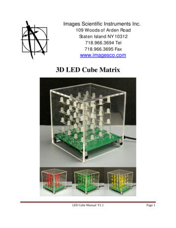
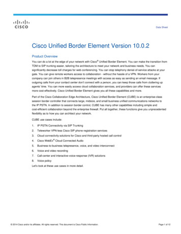
1The diagram shows a cube of glass. A ray of light, incident at the centre of a face of the cube, atan angle of incidence θ, goes on to meet another face at an angle of incidence of 50 , as shownin the figure bellowcritical angle at the glass-air boundary 45 (a)Draw on the diagram the continuation of the path of the ray, showing it passing through theglass and out into the air.(3)(b)Show that the refractive index of the glass is 1.41(2)(c)Calculate the angle of incidence, θ.(3)(Total 8 marks)St Bede's Catholic Comprehensive School and Byron CollegePage 1 of 83
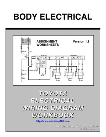
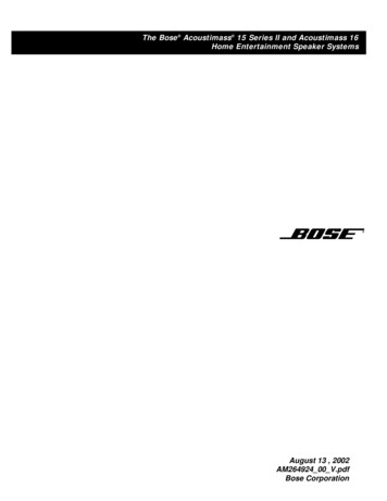
2Interference maxima produced by a double source are observed at a distance of 1.0 m from thesources. In which one of the following cases are the maxima closest together?Ared light of wavelength 700 nm from sources 4.0 mm apartBsound waves of wavelength 20 mm from sources 50 mm apartCblue light of wavelength 450 nm from sources 2.0 mm apartDsurface water waves of wavelength 10 mm from sources 200 mm apart(Total 1 mark)3The figure below shows a ray of light passing from air into glass at the top face of glass block 1and emerging along the bottom face of glass block 2.refractive index of the glass in block 1 1.45St Bede's Catholic Comprehensive School and Byron CollegePage 2 of 83
(a)Calculate(i)the incident angle θ1,(ii)the refractive index of the glass in block 2,(iii)the angle θ3 by considering the refraction at point A.(7)(b)In which of the two blocks of glass will the speed of light be greater?Explain your reasoning.(2)(c)Using a ruler, draw the path of a ray partially reflected at A on the figure above. Continuethe ray to show it emerging into the air. No calculations are expected.(2)(Total 11 marks)St Bede's Catholic Comprehensive School and Byron CollegePage 3 of 83
4(a)For an optical fibre the refractive index of the core is 1.52 and the refractive index of thecladding is 1.49. Calculate the critical angle, in degrees, at the boundary between the coreand cladding of the fibre.critical angle degrees(2)(b)Explain why the cladding is necessary for optical fibres.(2)(Total 4 marks)St Bede's Catholic Comprehensive School and Byron CollegePage 4 of 83
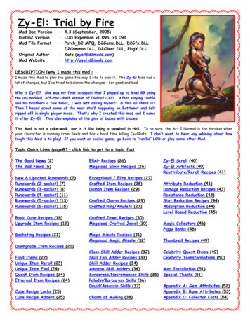
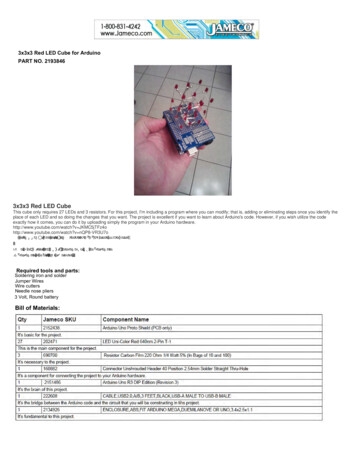
5A ray of light passes from air into a glass prism as shown in Figure 1.Figure 1(a)Confirm, by calculation, that the refractive index of the glass from which the prism wasmade is 1.49.(1)(b)On Figure 1, draw the continuation of the path of the ray of light until it emerges back intothe air. Write on Figure 1 the values of the angles between the ray and any normals youhave drawn.the critical angle from glass to air is less than 45 (2)St Bede's Catholic Comprehensive School and Byron CollegePage 5 of 83
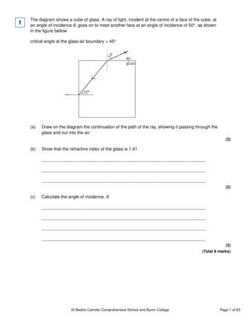
(c)A second prism, prism 2, made from transparent material of refractive index 1.37 is placedfirmly against the original prism, prism 1, to form a cube as shown in Figure 2.Figure 2(i)The ray strikes the boundary between the prisms. Calculate the angle of refraction ofthe ray in prism 2.(ii)Calculate the speed of light in prism 2.(iii)Draw a path the ray could follow to emerge from prism 2 into the air.(7)(Total 10 marks)St Bede's Catholic Comprehensive School and Byron CollegePage 6 of 83
6The diagram above shows the first four diffraction orders each side of the zero order when abeam of monochromatic light is incident normally on a diffraction grating of slit separation d. Allthe angles of diffraction are small. Which one of the patterns, A to D, drawn on the same scale,is obtained when the grating is exchanged for one with a slit separation?ABCD(Total 1 mark)St Bede's Catholic Comprehensive School and Byron CollegePage 7 of 83
7In a double slit system used to produce interference fringes, the separation of the slits is s andthe width of each slit is x. L is a source of monochromatic light. Which one of the followingchanges would decrease the separation of the fringes seen on the screen?Amoving the screen closer to the double slitsBdecreasing the width, x, of each slit, but keeping s constantCdecreasing the separation, s, of the slitsDexchanging L for a monochromatic source of longer wavelength(Total 1 mark)8A diffraction grating has 300 lines per mm. It is illuminated with monochromatic light ofwavelength 540 nm.Calculate the angle of the 2nd order maximum, giving your answer to the appropriate number ofsignificant figures.angle degrees(Total 4 marks)St Bede's Catholic Comprehensive School and Byron CollegePage 8 of 83
9A narrow beam of monochromatic red light is directed at a double slit arrangement. Parallel redand dark fringes are seen on the screen shown in the diagram above.(a)(i)Light passing through each slit spreads out. What is the name for this effect?(1)(ii)Explain the formation of the fringes seen on the screen.(4)(iii)The slit spacing was 0.56 mm. The distance across 4 fringe spacings was 3.6 mmwhen the screen was at a distance of 0.80 m from the slits. Calculate the wavelengthof the red light.Answer m(4)St Bede's Catholic Comprehensive School and Byron CollegePage 9 of 83
(b)Describe how the appearance of the fringes would differ if white light had been usedinstead of red light.(3)(Total 12 marks)10A laser illuminates a pair of slits of separation 0.24 mm. The wavelength of light from the laser is6.3 10–7 m. Interference fringes are observed on a screen 4.3 m from the slits.(a)Calculate the fringe separation. Give an appropriate unit for your answer.fringe separation(3)(b)State the conditions necessary for two light sources to be coherent.(2)(Total 5 marks)St Bede's Catholic Comprehensive School and Byron CollegePage 10 of 83
11The diagram below shows a rectangular glass fish tank containing water. Three light rays,P, Q and R from the same point on a small object O at the bottom of the tank are shown.(a)(i)Light ray Q is refracted along the water-air surface. The angle of incidence of light rayQ at the water surface is 49.0 . Calculate the refractive index of the water. Give youranswer to an appropriate number of significant figures.Answer(1)(ii)Draw on the diagram above the path of light ray P from the water-air surface.(3)(b)In the diagram above, the angle of incidence of light ray R at the water-air surface is 60.0 .(i)Explain why this light ray is totally internally reflected at the water surface.(2)St Bede's Catholic Comprehensive School and Byron CollegePage 11 of 83
(ii)Draw the path of light ray R from the water surface and explain whether or not Renters the glass at the right-hand side of the tank.the refractive index of the glass 1.50(4)(Total 10 marks)St Bede's Catholic Comprehensive School and Byron CollegePage 12 of 83
12An optical fibre used for communications has a core of refractive index 1.55 which is surroundedby cladding of refractive index 1.45.(a)The diagram above shows a light ray P inside the core of the fibre. The light ray strikes thecore-cladding boundary at Q at an angle of incidence of 60.0 .(i)Calculate the critical angle of the core-cladding boundary.answer degrees(3)(ii)State why the light ray enters the cladding at Q.(1)(iii)Calculate the angle of refraction, θ, at Q.answer degrees(3)St Bede's Catholic Comprehensive School and Byron CollegePage 13 of 83
(b)Explain why optical fibres used for communications need to have cladding.(2)(Total 9 marks)13A narrow beam of monochromatic light of wavelength 590 nm is directed normally at a diffractiongrating, as shown in the diagram below.(a)The grating spacing of the diffraction grating is 1.67 10–6 m.(i)Calculate the angle of diffraction of the second order diffracted beam.answer degrees(4)(ii)Show that no beams higher than the second order can be observed at thiswavelength.(3)St Bede's Catholic Comprehensive School and Byron CollegePage 14 of 83
(b)The light source is replaced by a monochromatic light source of unknown wavelength.A narrow beam of light from this light source is directed normally at the grating.Measurement of the angle of diffraction of the second order beam gives a value of 42.1 .Calculate the wavelength of this light source.answer m(2)(Total 9 marks)14Just over two hundred years ago Thomas Young demonstrated the interference of light byilluminating two closely spaced narrow slits with light from a single light source.(a)What did this suggest to Young about the nature of light?(1)(b)The demonstration can be carried out more conveniently with a laser. A laser producescoherent, monochromatic light.(i)State what is meant by monochromatic.(ii)State what is meant by coherent.(2)(iii)State one safety precaution that should be taken while using a laser.(1)St Bede's Catholic Comprehensive School and Byron CollegePage 15 of 83
(c)The diagram below shows the maxima of a two slit interference pattern produced on ascreen when a laser was used as a monochromatic light source.The slit spacing 0.30 mm.The distance from the slits to the screen 10.0 m.Use the diagram above to calculate the wavelength of the light that produced the pattern.answer m(3)(d)The laser is replaced by another laser emitting visible light with a shorter wavelength.State and explain how this will affect the spacing of the maxima on the screen.(2)(Total 9 marks)St Bede's Catholic Comprehensive School and Byron CollegePage 16 of 83
15The diagram below shows a cross-section through a step index optical fibre.(a)(i)Name the parts A and B of the fibre.AB(1)(ii)On the diagram above, draw the path of the ray of light through the fibre.Assume the light ray undergoes total internal reflection at the boundary betweenA and B.(2)(b)Calculate the critical angle for the boundary between A and B.Give your answer to an appropriate number of significant figures.The refractive index of part A 1.46The refractive index of part B 1.48answer degrees(2)(c)State and explain one reason why part B of the optical fibre is made as narrow as possible.(2)St Bede's Catholic Comprehensive School and Byron CollegePage 17 of 83
(d)State one application of optical fibres and explain how this has benefited society.ApplicationBenefit(2)(Total 9 marks)16The figure below shows two rays of light A and B travelling through a straight optical fibre.(a)Calculate the speed of light in the core of the optical fibre.absolute refractive index of the core of the optical fibre 1.6speed of light in the core ms–1(2)St Bede's Catholic Comprehensive School and Byron CollegePage 18 of 83
(b)The overall length of the optical fibre is 0.80 km. As shown in the figure above, ray Atravels down the centre of the core of the optical fibre. The path of ray B has an overalllength of 0.92 km as it travels through the core.(i)Ray A and ray B enter the fibre at the same instant.Calculate the difference in time taken for ray A and ray B to travel through the core ofthe optical fibre.time difference s(2)(ii)Explain how a graded-index optical fibre prevents this time difference occurring forrays such as A and B in the figure above.(2)(Total 6 marks)St Bede's Catholic Comprehensive School and Byron CollegePage 19 of 83
17A glass cube is held in contact with a liquid and a light ray is directed at a vertical face of thecube. The angle of incidence at the vertical face is then decreased to 42 as shown in the figurebelow. At this point the angle of refraction is 27 and the ray is totally internally reflected at P forthe first time.(a)Complete the figure above to show the path of the ray beyond P until it returns to air.(3)(b)Show that the refractive index of the glass is about 1. 5.(2)(c)Calculate the critical angle for the glass-liquid boundary.answer degrees(1)St Bede's Catholic Comprehensive School and Byron CollegePage 20 of 83
(d)Calculate the refractive index of the liquid.answer (2)(Total 8 marks)18For a plane transmission diffraction grating, the diffraction grating equation for the first orderbeam is:λ d sin θ(a)The figure below shows two of the slits in the grating. Label the figure below with thedistances d and λ.(2)(b)State and explain what happens to the value of angle θ for the first order beam if thewavelength of the monochromatic light decreases.(2)St Bede's Catholic Comprehensive School and Byron CollegePage 21 of 83
(c)A diffraction grating was used with a spectrometer to obtain the line spectrum of star Xshown in the figure below. Shown are some line spectra for six elements that have beenobtained in the laboratory.Place ticks in the boxes next to the three elements that are present in the atmosphere ofstar X.(2)(d)The diffraction grating used to obtain the spectrum of star X had 300 slits per mm.(i)Calculate the distance between the centres of two adjacent slits on this grating.answer m(1)(ii)Calculate the first order angle of diffraction of line P in the figure above.answer degrees(2)(Total 9 marks)St Bede's Catholic Comprehensive School and Byron CollegePage 22 of 83
19A single slit diffraction pattern is produced on a screen using a laser. The intensity of the centralmaximum is plotted on the axes in the figure below.(a)On the figure above, sketch how the intensity varies across the screen to the right of thecentral maximum.(2)(b)A laser is a source of monochromatic, coherent light. State what is meant bymonochromatic lightcoherent light(2)(c)Describe how the pattern would change if light of a longer wavelength was used.(1)(d)State two ways in which the appearance of the fringes would change if the slit was madenarrower.(2)St Bede's Catholic Comprehensive School and Byron CollegePage 23 of 83
(e)The laser is replaced with a lamp that produces a narrow beam of white light. Sketch andlabel the appearance of the fringes as you would see them on a screen.(3)(Total 10 marks)20The figure below shows a cross-section through an optical fibre.(a)Explain the purpose of part X.(1)St Bede's Catholic Comprehensive School and Byron CollegePage 24 of 83
(b)The critical angle for the optical fibre is to be 60 and the absolute refractive index for theglass in the core of the fibre is 1.6.Calculate the required absolute refractive index for part Y.absolute refractive index for part Y(3)(c)Explain why dispersion occurs in an optical fibre.(2)(Total 6 marks)St Bede's Catholic Comprehensive School and Byron CollegePage 25 of 83
21Figure 1 shows a cross-section through an optical fibre used for communications.Figure 1(a)(i)Name the part of the fibre labelled X.(1)(ii)Calculate the critical angle for the boundary between the core and X.answer degrees(2)St Bede's Catholic Comprehensive School and Byron CollegePage 26 of 83
(b)(i)The ray leaves the core at Y. At this point the fibre has been bent through an angle of30 as shown in Figure 1.Calculate the value of the angle i.answer degrees(1)(ii)Calculate the angle r.answer degrees(2)St Bede's Catholic Comprehensive School and Byron CollegePage 27 of 83
(c)The core of another fibre is made with a smaller diameter than the first, as shown in Figure2. The curvature is the same and the path of a ray of light is shown.Figure 2(c)State and explain one advantage associated with a smaller diameter core.(2)(Total 8 marks)St Bede's Catholic Comprehensive School and Byron CollegePage 28 of 83
22(a)The speed of light is given byc fλState how each of these quantities will change, if at all, when light travels from air to glass.cfλ(3)Figure 1 shows a side view of a step index optical fibre.Figure 1(b)Ray A enters the end of the fibre and then undergoes total internal reflection.On Figure 1 complete the path of this ray along the fibre.(2)(c)(i)The speed of light in the core is 2.04 108 ms–1. Show that the refractive index of thecore is 1.47.(2)(ii)Show that the critical angle at the boundary between the core and the cladding isabout 80 .refractive index of the cladding 1.45(2)St Bede's Catholic Comprehensive School and Byron CollegePage 29 of 83
(d)Ray B enters the end of the fibre and refracts along the core-cladding boundary. Calculatethe angle of incidence, θ, of this ray at the point of entry to the fibre.answer degrees(3)(e)Figure 2 shows a pulse of monochromatic light (labelled X) that is transmitted a significantdistance along the fibre. The shape of the pulse after travelling along the fibre is labelled Y.Explain why the pulse at Y has a lower amplitude and is longer than it is at X.Figure 2(2)(Total 14 marks)St Bede's Catholic Comprehensive School and Byron CollegePage 30 of 83
23The diagram below shows a section of a typical glass step-index optical fibre used forcommunications.(a)Show that the refractive index of the core is 1.47.(1)(b)The refracted ray meets the core-cladding boundary at an angle exactly equal to the criticalangle.(i)Complete the diagram above to show what happens to the ray after it strikes theboundary at X.(2)(ii)Calculate the critical angle.critical angle degrees(1)(iii)Calculate the refractive index of the cladding.refractive index (2)St Bede's Catholic Comprehensive School and Byron CollegePage 31 of 83
(c)Give two reasons why optical fibres used for communications have a cladding.reason 1reason 2(2)(Total 8 marks)24The figure below shows a glass prism. Light is directed into the prism at an angle of 56 .The path of the ray of light is shown as is it enters the prism.(a)(i)Calculate the refractive index of the glass.answer (2)(ii)Calculate the critical angle for the glass-air boundary.answer degrees(2)St Bede's Catholic Comprehensive School and Byron CollegePage 32 of 83
(b)On the figure above, continue the path of the ray of light until it emerges from the prism.(2)(Total 6 marks)25The diagram below shows three transparent glass blocks A, B and C joined together. Each glassblock has a different refractive index.(a)State the two conditions necessary for a light ray to undergo total internal reflection at theboundary between two transparent media.condition 1condition 2(2)St Bede's Catholic Comprehensive School and Byron CollegePage 33 of 83
(b)Calculate the speed of light in glass A.refractive index of glass A 1.80speed of light ms 1(2)(c)Show that angle θ is about 30o.(2)(d)The refractive index of glass C is 1.40.Calculate the critical angle between glass A and glass C.critical angle degrees(2)(e)(i)State and explain what happens to the light ray when it reaches the boundarybetween glass A and glass C.(2)(ii)On the diagram above continue the path of the light ray after it strikes the boundarybetween glass A and glass C.(1)(Total 11 marks)St Bede's Catholic Comprehensive School and Byron CollegePage 34 of 83
26The figure below shows a spectrometer that uses a diffraction grating to split a beam of light intoits constituent wavelengths and enables the angles of the diffracted beams to be measured.(a)Give one possible application of the spectrometer and diffraction grating used in this way.(1)(b)(i)When the spectrometer telescope is rotated from an initial angle of zero degrees, aspectrum is not observed until the angle of diffraction θ is about 50 . State the orderof this spectrum.(1)(ii)White light is directed into the spectrometer. Light emerges at A and B. State onedifference between the light emerging at B compared to that emerging at A.(1)St Bede's Catholic Comprehensive School and Byron CollegePage 35 of 83
(c)The angle of diffraction θ at the centre of the observed beam B in the image above is 51.0 and the grating has 1480 lines per mm.Calculate the wavelength of the light observed at the centre of beam B.wavelength m(3)(d)Determine by calculation whether any more orders could be observed at the wavelengthcalculated in part (c).(2)(Total 8 marks)27(a)A laser emits monochromatic light.Explain the meaning of the term monochromatic light.(1)St Bede's Catholic Comprehensive School and Byron CollegePage 36 of 83
(b)The diagram below shows a laser emitting blue light directed at a single slit, where the slitwidth is greater than the wavelength of the light. The intensity graph for the diffracted bluelight is shown.The laser is replaced by a laser emitting red light.On the axes shown in the diagram above sketch the intensity graph for a laser emitting redlight.(2)(c)State and explain one precaution that should be taken when using laser light(2)St Bede's Catholic Comprehensive School and Byron CollegePage 37 of 83
(d)The red laser light is replaced by a non-laser source emitting white light.Describe how the appearance of the pattern would change.(3)(Total 8 marks)28Figure 1 shows a ray of light A incident at an angle of 60 to the surface of a layer of oil that isfloating on water.refractive index of oil 1.47refractive index of water 1.33Figure 1(a)(i)Calculate the angle of refraction θ in Figure 1.angle degrees(2)St Bede's Catholic Comprehensive School and Byron CollegePage 38 of 83
(ii)Calculate the critical angle for a ray of light travelling from oil to water.angle degrees(2)(iii)On Figure 1 continue the path of the ray of light A immediately after it strikes theboundary between the oil and the water.(2)(b)In Figure 2 a student has incorrectly drawn a ray of light B entering the glass and thenentering the water before totally internally reflecting from the water–oil boundary.Figure 2The refractive index of the glass is 1.52 and the critical angle for the glass–water boundaryis about 60 .St Bede's Catholic Comprehensive School and Byron CollegePage 39 of 83
Give two reasons why the ray of light B would not behave in this way. Explain youranswers.reason 1explanationreason 2explanation(4)(Total 10 marks)29The diagram shows Young’s double-slit experiment performed with a tungsten filament lamp asthe light source.(a)On the axes in the diagram above, sketch a graph to show how the intensity varies withposition for a monochromatic light source.(2)St Bede's Catholic Comprehensive School and Byron CollegePage 40 of 83
(b)(i)For an interference pattern to be observed the light has to be emitted by twocoherent sources.Explain what is meant by coherent sources.(1)(ii)Explain how the use of the single slit in the arrangement above makes the light fromthe two slits sufficiently coherent for fringes to be observed.(1)(iii)In this experiment light behaves as a wave.Explain how the bright fringes are formed.(3)St Bede's Catholic Comprehensive School and Byron CollegePage 41 of 83
(c)(i)A scientist carries out the Young double-slit experiment using a laser that emits violetlight of wavelength 405 nm. The separation of the slits is 5.00 10–5 m.Using a metre ruler the scientist measures the separation of two adjacent brightfringes in the central region of the pattern to be 4 mm.Calculate the distance between the double slits and the screen.distance m(2)(ii)Describe the change to the pattern seen on the screen when the violet laser isreplaced by a green laser. Assume the brightness of the central maximum is thesame for both lasers.(1)(iii)The scientist uses the same apparatus to measure the wavelength of visibleelectromagnetic radiation emitted by another laser.Describe how he should change the way the apparatus is arranged and used in orderto obtain an accurate value for the wavelength.(3)(Total 13 marks)St Bede's Catholic Comprehensive School and Byron CollegePage 42 of 83
30An optical fibre consists of a core, cladding and an outer sheath.(a)State the purpose of the outer sheath in an optical fibre.(1)(b)For one fibre, the speed of monochromatic light in the core is 1.97 108 m s 1 and thespeed in the cladding is 2.03 108 m s 1.Calculate the critical angle for this light at the interface between the core and the cladding.critical angle degrees(2)(Total 3 marks)31Diamond jewels sparkle because light that enters the diamond at different incident angles isreflected back to an observer. Figure 1 shows the path of one of these incident rays through adiamond.Figure 1St Bede's Catholic Comprehensive School and Byron CollegePage 43 of 83
(a)(i)Calculate the critical angle for diamond.Refractive index of diamond 2.42critical angle degree(2)(ii)The ray shown in Figure 1 enters at an angle of incidence of 50.2 .Calculate the angle of refraction θ.θ degree(2)(iii)The angles of a diamond are chosen to maximise the amount of light reflected.Figure 2 shows a diamond with different angles to that of a normally shapeddiamond. The dotted lines show the normal shape of a diamond.Figure 2Draw on Figure 2 the path of the ray until it leaves the diamond.(2)St Bede's Catholic Comprehensive School and Byron CollegePage 44 of 83
(iv)Moissanite is a transparent material with a refractive index of 2.67.Discuss whether this material, if made to the diamond shape shown in Figure 1,would reflect light back more or less than diamond.(2)(b)Figure 3 shows an infrared ray entering an optical fibre. The refractive index of the core is1.55 at infrared frequencies.Figure 3(i)Calculate the speed at which infrared radiation travels in the core.speed m s 1(1)St Bede's Catholic Comprehensive School and Byron CollegePage 45 of 83
(ii)The wavelength of this infrared radiation is 1300 nm in air.Calculate the wavelength of infrared in the core.wavelength m(2)(iii)State one reason for surrounding the core with cladding.(1)(Total 12 marks)32(a)Tick ( ) the appropriate boxes in the table to indicate how the wavelength, frequency andspeed of light are affected when a ray of light travels from air into glass.WavelengthFrequencySpeedincreasesstays the samedecreases(2)St Bede's Catholic Comprehensive School and Byron CollegePage 46 of 83
(b)Figure 1 shows a right-angled glass prism in contact with a transparent substance on oneof the faces. One of the other angles of the prism is θ.Figure 1(i)A ray A enters perpendicularly to one face of the prism. It is partially refracted andpartially reflected at the interface between the glass and the transparent substance.The angle of refraction is 65.0 . The ray eventually leaves at an angle α to thesurface of the transparent substance.Determine the angle α.angle α degree(2)(ii)Determine the angle θ in Figure 1.angle θ degree(2)St Bede's Catholic Comprehensive School and Byron CollegePage 47 of 83
(c)Figure 2 shows another ray entering the prism.Figure 2(i)Identify the effect that takes place at X in Figure 2.(1)(ii)Explain, with a diagram, how the effect that occurs at X is used to transmitinformation along an optic fibre.(3)(Total 10 marks)St Bede's Catholic Comprehensive School and Byron CollegePage 48 of 83
33Musicians can use tuning forks to tune their instruments.A tuning fork produces a specific frequency when it vibrates.Figure 1 shows a tuning fork vibrating in air at a single instant in time.The circles represent the positions of air particles in the sound wave.Figure 1(a)The tuning fork emits a wave that has a frequency of 0.51 kHz.(i)State the meaning of the term frequency of a wave.(1)(ii)Air particles vibrate in different phases in the direction in which the wave is travelling.Calculate the minimum separation of particles that vibrate 180 out of phase.speed of sound in air 340 m s–1minimum separation m(3)St Bede's Catholic Comprehensive School and Byron CollegePage 49 of 83
(b)A student sets a tuning fork of lower frequency vibrating at the same time as the 0.51 kHztuning fork in part (a).The student detects the resultant sound wave with a microphone. The variation with time ofthe voltage generated by the microphone is shown in Figure 2.Figure 2(i)Explain why the two tuning forks are not coherent sources of sound waves.(2)(ii)Explain why the resultant sound has a minimum amplitude at 50 ms.(3)St Bede's Catholic Comprehensive School and Byron CollegePage 50 of 83
(iii)Calculate the frequency of the tuning fork that emits the lower frequency.frequency Hz(3)(c)A signal generator connected to a loudspeaker produces a sinusoidal sound wave with afrequency of 440 Hz.The variation in air pressure with time for this sound is shown in Figure 3.Figure 3A violin string has a fundamental frequency (first harmonic) of 440 Hz.Figure 4 shows the variation in air pressure with time for the sound created by the violinstring.Figure 4St Bede's Catholic Comprehensive School and Byron CollegePage 51 of 83
(i)The two sounds have the same pitch but sound different.What term describes the difference between the sounds heard?Tick ( ) the correct answer.Frequency modulationOctavesPath differenceQuality(1)(ii)The complex sound in Figure 4 can be electronically synthesised.Describe the process of electronically synthesising this sound.(3)(Total 16 marks)St Bede's Catholic Comprehensive School and Byron CollegePage 52 of 83
34The diagram below shows the paths of microwaves from two narrow slits, acting as coherentsources, through a vacuum to a detector.(a)Explain what is meant by coherent sources.(2)(b)(i)The frequency of the microwaves is 9.4 GHz.Calculate the wavelength of the waves.wavelength m(2)St Bede's Catholic Comprehensive School and Byron CollegePage 53 of 83
(ii)Using the diagram above and your answer to part (b)(i), calculate the path differencebetween the two waves arriving at the detector.path difference m(1)(c)State and explain whether a maximum or minimum is detect
(b) The light source is replaced by a monochromatic light source of unknown wavelength. A narrow beam of light from this light source is directed normally at the grating. Measurement of the angle of diffraction of the second order beam gives a value of 42.1 . Calculate the wavelength of this light source.