Transcription
MIL-HDBK-17-3E, Working DraftCHAPTER 5STRUCTURAL BEHAVIOR OF JOINTSPage5.1 INTRODUCTION . 25.2 ADHESIVE JOINTS . 35.2.1 Introduction . 35.2.2 Joint design considerations . 45.2.2.1 Effects of adherend thickness: adherend failures vs. bond failures. 45.2.2.2 Joint geometry effects. 55.2.2.3 Effects of adherend stiffness unbalance . 65.2.2.4 Effects of ductile adhesive response . 65.2.2.5 Behavior of composite adherends . 85.2.2.6 Effects of bond defects . 95.2.2.7 Durability of adhesive joints . 105.2.3 Stress and structural behavior of adhesive joints . 125.2.3.1 General . 125.2.3.2 Adhesive shear stresses. 135.2.3.3 Peel stresses . 185.2.3.4 Single and double lap joints with uniform adherend thickness . 205.2.3.4.1 Joint behavior with elastic response of the bond layer . 205.2.3.4.2 Thermal stress effects . 295.2.3.4.3 Effect of ductility on joint stresses . 325.2.3.4.4 Transverse shear and stacking sequence effects in compositeadherends. 355.2.3.5 Tapered and multi-step adherends . 365.2.3.6 Finite element modeling . 475.2.4 Failure criteria for adhesive joints . 475.2.5 Design case studies. 475.3 MECHANICALLY FASTENED JOINTS . 505.3.1 Introduction . 505.3.2 Structural analysis . 505.3.2.1 Load sharing in a joint . 505.3.2.2 Analysis of local failure in bolted joints. 535.3.2.3 Failure criteria . 605.3.3 Design considerations . 615.3.3.1 Geometry . 615.3.3.2 Lay-up and stacking sequence . 615.3.3.3 Fastener selection. 615.3.4 Fatigue . 625.3.4.1 Influence of loading mode . 625.3.4.2 Influence of joint geometry . 635.3.4.3 Influence of attachment details . 635.3.4.4 Influence of laminate lay-up . 645.3.4.5 Influence of environment. 645.3.4.6 Influence of specimen thickness . 645.3.4.7 Residual strength . 645.3.5 Test verification. 64REFERENCES. 675-1
MIL-HDBK-17-3E, Working Draft5.1 INTRODUCTIONIt would be difficult to conceive of a structure that did not involve some type of joint. Joints often occurin transitions between major composite parts and a metal feature or fitting. In aircraft, such a situation isrepresented by articulated fittings on control surfaces as well as on wing and tail components which require the ability to pivot the element during various stages of operation. Tubular elements such as powershafting often use metal end fittings for connections to power sources or for articulation where changes indirection are needed. In addition, assembly of the structure from its constituent parts will involve eitherbonded or mechanically fastened joints or both.Joints represent one of the greatest challenges in the design of structures in general and in compositestructures in particular. The reason for this is that joints entail interruptions of the geometry of the structure and often, material discontinuities, which almost always produce local highly stressed areas, exceptfor certain idealized types of adhesive joint such as scarf joints between similar materials. Stress concentrations in mechanically fastened joints are particularly severe because the load transfer between elements of the joint have to take place over a fraction of the available area. For mechanically fastened jointsin metal structures, local yielding, which has the effect of eliminating stress peaks as the load increases,can usually be depended on; such joints can be designed to some extent by the "P over A" approach, i.e.,by assuming that the load is evenly distributed over load bearing sections so that the total load (the "P")divided by the available area (the "A") represents the stress that controls the strength of the joint. In organic matrix composites, such a stress reduction effect is realized only to a minor extent, and stresspeaks predicted to occur by elastic stress analysis have to be accounted for, especially for one-time monotonic loading. In the case of composite adherends, the intensity of the stress peaks varies with the orthotropy of the adherend in addition to various other material and dimensional parameters which affect thebehavior of the joint for isotropic adherends.In principle, adhesive joints are structurally more efficient than mechanically fastened joints becausethey provide better opportunities for eliminating stress concentrations; for example, advantage can betaken of ductile response of the adhesive to reduce stress peaks. Mechanically fastened joints tend touse the available material inefficiently. Sizeable regions exist where the material near the fastener isnearly unloaded, which must be compensated for by regions of high stress to achieve a particular requiredaverage load. As mentioned above, certain types of adhesive joints, namely scarf joints between components of similar stiffness, can achieve a nearly uniform stress state throughout the region of the joint.In many cases, however, mechanically fastened joints can not be avoided because of requirementsfor disassembly of the joint for replacement of damaged structure or to achieve access to underlyingstructure. In addition, adhesive joints tend to lack structural redundancy, and are highly sensitive tomanufacturing deficiencies, including poor bonding technique, poor fit of mating parts and sensitivity of theadhesive to temperature and environmental effects such as moisture. Assurance of bond quality hasbeen a continuing problem in adhesive joints; while ultrasonic and X-ray inspection may reveal gaps in thebond, there is no present technique which can guarantee that a bond which appears to be intact does, infact, have adequate load transfer capability. Surface preparation and bonding techniques have been welldeveloped, but the possibility that lack of attention to detail in the bonding operation may lead to such deficiencies needs constant alertness on the part of fabricators. Thus mechanical fastening tends to be preferred over bonded construction in highly critical and safety rated applications such as primary aircraftstructural components, especially in large commercial transports, since assurance of the required level ofstructural integrity is easier to guarantee in mechanically fastened assemblies. Bonded construction tendsto be more prevalent in smaller aircraft. For non-aircraft applications as well as in non-flight critical aircraftcomponents, bonding is likewise frequently used.This chapter describes design procedures and analytical methods for determining stresses and deformations in structural joints for composite structures. Section 5.2 which follows deals with adhesivejoints. (Mechanically fastened joints will be the subject of a future revision of the Handbook.)5-2
MIL-HDBK-17-3E, Working DraftIn the case of adhesive joints, design considerations which are discussed include: effects of adherendthickness as a means of ensuring adherend failure rather than bond failure; the use of adherend taperingto minimize peel stresses; effects of adhesive ductility; special considerations regarding composite adherends; effects of bond layer defects, including surface preparations defects, porosity and thickness variations; and, considerations relating to long term durability of adhesive joints. In addition to design considerations, aspects of joint behavior which control stresses and deformations in the bond layer are described, including both shear stresses and transverse normal stresses which are customarily referred toas "peel" stresses when they are tensile. Finally, some principles for finite element analysis of bondedjoints are described.Related information on joints in composite structures which is described elsewhere in this handbookincludes Volume 1, Chapter 7, Section 7.2 (Mechanically Fastened Joints) and 7.3 (Bonded Joints) together with Volume 3, Chapter 2, Section 2.7.8 on Adhesive Bonding.5.2 ADHESIVE JOINTS5.2.1 IntroductionAdhesive joints are capable of high structural efficiency and constitute a resource for structural weightsaving because of the potential for elimination of stress concentrations which cannot be achieved withmechanically fastened joints. Unfortunately, because of a lack of reliable inspection methods and a requirement for close dimensional tolerances in fabrication, aircraft designers have generally avoidedbonded construction in primary structure. Some notable exceptions include: bonded step lap joints usedin attachments for the F-14 and F-15 horizontal stabilizers as well as the F-18 wing root fitting, and a majority of the airframe components of the Lear Fan and the Beech Starship.While a number of issues related to adhesive joint design were considered in the earlier literature citedin Reference 5.2.1(a)- 5.2.1(h), much of the methodology currently used in the design and analysis of adhesive joints in composite structures is based on the approaches evolved by L.J. Hart-Smith in a series ofNASA/Langley-sponsored contracts of the early 70's (Reference 5.2.1(i) - 5.2.1(n)) as well as from the AirForce's Primary Adhesively Bonded Structures Technology (PABST) program (Reference 5.2.1(o) 5.2.1(r)) of the mid-70's. The most recent such work developed three computer codes for bonded andbolted joints, designated A4EG, A4EI and A4EK (References 5.2.1(s) - 5.2.1(u)), under Air Force contract. The results of these efforts have also appeared in a number of open literature publications(Reference 5.2.1(v) - (z)). In addition, such approaches found application in some of the efforts takingplace under the NASA Advanced Composite Energy Efficient Aircraft (ACEE) program of the early to mid80's (Reference 5.2.1(x) and 5.2.1(y)).Some of the key principles on which these efforts were based include: (1) the use of simple1-dimensional stress analyses of generic composite joints wherever possible; (2) the need to select thejoint design so as to ensure failure in the adherend rather than the adhesive, so that the adhesive is neverthe weak link; (3) recognition that the ductility of aerospace adhesives is beneficial in reducing stresspeaks in the adhesive; (4) careful use of such factors as adherend tapering to reduce or eliminate peelstresses from the joint; and (5) recognition of slow cyclic loading, corresponding to such phenomena ascabin pressurization in aircraft, as a major factor controlling durability of adhesive joints, and the need toavoid the worst effects of this type of loading by providing sufficient overlap length to ensure that some ofthe adhesive is so lightly loaded that creep cannot occur there, under the most severe extremes of humidity and temperature for which the component is to be used.Much of the discussion to follow will retain the analysis philosophy of Hart-Smith, since it is consideredto represent a major contribution to practical bonded joint design in both composite and metallic structures. On the other hand, some modifications are introduced here. For example, the revisions of the Goland-Reissner single lap joint analysis presented in Reference 5.2.1(k) have again been revised accordingto the approach presented in References 5.2.1(z) and 5.2.1(aa).5-3
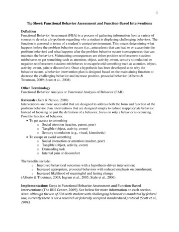
MIL-HDBK-17-3E, Working DraftCertain issues which are specific to composite adherends but were not dealt with in the Hart-Smithefforts will be addressed. The most important of these is the effect of transverse shear deformations inorganic composite adherends.Although the main emphasis of the discussion is on simplified stress analysis concepts allowed byshear lag models for shear stress prediction and beam-on-elastic foundation concepts for peel stress prediction, a brief discussion will be provided on requirements for finite element modeling of adhesive joints.Similarly, although joint failure will be considered primarily from the standpoint of stress and strain energyconsiderations, some discussion of fracture mechanics considerations for adhesive joints will also be included.5.2.2 Joint design considerations5.2.2.1 Effects of adherend thickness: adherend failures vs. bond failuresFigure 5.2.2.1(a) shows a series of typical bonded joint configurations. Adhesive joints in general arecharacterized by high stress concentrations in the adhesive layer. These originate, in the case of shearstresses, because of unequal axial straining of the adherends, and in the case of peel stresses, becauseof eccentricity in the load path. Considerable ductility is associated with shear response of typical adhesives, which is beneficial in minimizing the effect of shear stress joint strength. Response to peel stressestends to be much more brittle than that to shear stresses, and reduction of peel stresses is desirable forachieving good joint performance.FIGURE 5.2.2.1(a) Adhesive joint types (Reference 5.2.1(n) and 5.2.2.1(a)).From the standpoint of joint reliability, it is vital to avoid letting the adhesive layer be the weak link inthe joint; this means that, whenever possible, the joint should be designed to ensure that the adherendsfail before the bond layer. This is because failure in the adherends is fiber controlled, while failure in theadhesive is resin dominated, and thus subject to effects of voids and other defects, thickness variations,environmental effects, processing variations, deficiencies in surface preparation and other factors that arenot always adequately controlled. This is a significant challenge, since adhesives are inherently muchweaker than the composite or metallic elements being joined. However, the objective can be accomplished by recognizing the limitations of the joint geometry being considered and placing appropriate restrictions on the thickness dimensions of the joint for each geometry. Figure 5.2.2.1(b),which has frequently been used by Hart-Smith (References 5.2.1(n), 5.2.2.1(a)) to illustrate this point, shows a progression of joint types which represent increasing strength capability from the lowest to the highest in the figure. In each type of joint, the adherend thickness may be increased as an approach to achieving higher5-4
MIL-HDBK-17-3E, Working Draftload capacity. When the adherends are relatively thin, results of stress analyses show that for all of thejoint types in Figure 5.2.2.1(b), the stresses in the bond will be small enough to guarantee that the adherends will reach their load capacity before failure can occur in the bond. As the adherend thicknesses increase, the bond stresses become relatively larger until a point is reached at which bond failure occurs ata lower load than that for which the adherends fail. This leads to the general principle that for a given jointtype, the adherend thicknesses should be restricted to an appropriate range relative to the bond layerthickness. Because of processing considerations and defect sensitivity of the bond material, bond layerthicknesses are generally limited to a range of 0.005-0.015 in. (0.125-0.39 mm). As a result, each of thejoint types in Figure 5.2.2.1(a) and 5.2.2.1(b) corresponds to a specific range of adherend thicknesses andtherefore of load capacity, and as the need for greater load capacity arises, it is preferable to change thejoint configuration to one of higher efficiency rather than to increasing the adherend thickness indefinitely.FIGURE 5.2.2.1(b) Joint geometry effects (Reference 5.2.1(n)).5.2.2.2 Joint geometry effectsSingle and double lap joints with uniformly thick adherends (Figure 5.2.2.1(a) - Joints (B), (E) and (F))are the least efficient joint type and are suitable primarily for thin structures with low running loads (loadper unit width, i.e., stress times element thickness). Of these, single lap joints are the least capable because the eccentricity of this type of geometry generates significant bending of the adherends that magnifies the peel stresses. Peel stresses are also present in the case of symmetric double lap and doublestrap joints, and become a limiting factor on joint performance when the adherends are relatively thick.5-5
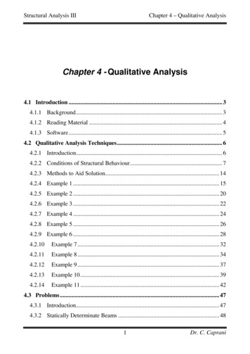
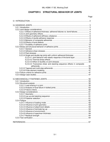
MIL-HDBK-17-3E, Working DraftTapering of the adherends (Figure 5.2.2.1(a) - Joints (D) and (G)) can be used to eliminate peelstresses in areas of the joint where the peel stresses are tensile, which is the case of primary concern.No tapering is needed at ends of the overlap where the adherends butt together because the transversenormal stress at that location is compressive and rather small. Likewise, for double strap joints undercompressive loading, there is no concern with peel stresses at either location since the transverse extensional stresses that do develop in the adhesive are compressive in nature rather than tensile; indeed,where the gap occurs, the inner adherends bear directly on each other and no stress concentrations arepresent there for the compression loading case.For joints between adherends of identical stiffness, scarf joints (Figure 5.2.2.1(a) - Joint (I)) are theoretically the most efficient, having the potential for complete elimination of stress concentrations. (In practice, some minimum thickness corresponding to one or two ply thicknesses must be incorporated at thethin end of the scarfed adherend leading to the occurrence of stress concentrations in these areas.) Intheory, any desirable load capability can be achieved in the scarf joint by making the joint long enough andthick enough. However, practical scarf joints may be less durable because of a tendency toward creepfailure associated with a uniform distribution of shear stress along the length of the joint unless care istaken to avoid letting the adhesive be stressed into the nonlinear range. As a result, scarf joints tend to beused only for repairs of very thin structures. Scarf joints with unbalanced stiffnesses between the adherends do not achieve the uniform shear stress condition of those with balanced adherends, and are somewhat less structurally efficient because of rapid buildup of load near the thin end of the thicker adherend.Step lap joints (Figure 5.2.2.1(a) - Joint (H)) represent a practical solution to the challenge of bondingthick members. These types of joint provide manufacturing convenience by taking advantage of the layered structure of composite laminates. In addition, high loads can be transferred if sufficiently many shortsteps of sufficiently small "rise" (i.e., thickness increment) in each step are used, while maintaining sufficient overall length of the joint.5.2.2.3 Effects of adherend stiffness unbalanceAll types of joint geometry are adversely affected by unequal adherend stiffnesses, where stiffness isdefined as axial or in-plane shear modulus times adherend thickness. Where possible, the stiffnessesshould be kept approximately equal. For example, for step lap and scarf joints between quasi-isotropiccarbon/epoxy (Young's modulus 8 Msi (55 GPa)) and titanium (Young's modulus 16 Msi (110 GPa))ideally, the ratio of the maximum thickness (the thickness just beyond the end of the joint) of the composite adherend to that of the titanium should be 16/8 2.0.5.2.2.4 Effects of ductile adhesive responseAdhesive ductility is an important factor in minimizing the adverse effects of shear and peel stresspeaks in the bond layer. Figure 5.2.2.4(a) reconstructed from Reference 5.2.2.4(a) shows the shearstress-strain response characteristics of typical adhesives used in the aerospace industry as obtainedfrom thick adherend tests (Volume 1, Section 7.3). Figure 5.2.2.4(a), part (A) represents a relatively ductile film adhesive, FM73, under various environmental conditions, while Figure 5.2.2.4(a), part (B) represents a more brittle adhesive (FM400) under the same conditions. Similar curves can be found in othersources such as Reference 5.2.2.4(b). Even for the less ductile material such as that represented in Figure 5.2.2.4(a), part (B), ductility has a pronounced influence on mechanical response of bonded joints, andrestricting the design to elastic response deprives the application of a significant amount of additionalstructural capability. In addition to temperature and moisture, effects of porosity in the bond layer can havean influence on ductile response. Porosity effects are illustrated in Figure 5.2.2.4(b) (Reference 5.2.1(s))which compares the response of FM73 for porous (x symbols) and non-porous (diamond symbols) bondlayers for various environmental conditions. This will be further discussed in Section 5.2.2.6.5-6
MIL-HDBK-17-3E, Working DraftFIGURE 5.2.2.4(a) Typical characteristics of aerospace adhesives (Reference 5.2.2.4(a)).FIGURE 5.2.2.4(b) Effect of porosity on adhesive stress-strain characteristics (Reference 5.2.1(s)).If peel stresses can be eliminated from consideration by such approaches as adherend tapering,strain energy to failure of the adhesive in shear has been shown by Hart-Smith (Reference 5.2.1(i)) to bethe key parameter controlling joint strength; thus the square root of the adhesive strain energy density tofailure determines the maximum static load that can be applied to the joint. The work of Hart-Smith hasalso shown that for predicting mechanical response of the joint, the detailed stress-strain curve of the adhesive can be replaced by an equivalent curve consisting of a linear rise followed by a constant stressplateau (i.e. elastic-perfectly plastic response) if the latter is adjusted to provide a strain energy density tofailure equal to that of the actual stress-strain curve gives. Test methods for adhesives (see Volume 1,Section 7.3) should be aimed at providing data on this parameter . Once the equivalent elastic-perfectly5-7
MIL-HDBK-17-3E, Working Draftplastic stress strain curve has been identified for the selected adhesive in the range of the most severeenvironmental conditions (temperature and humidity) of interest, the joint design can proceed through theuse of relatively simple one-dimensional stress analysis, thus avoiding the need for elaborate finite element calculations. Even the most complicated of joints, the step lap joints designed for root-end wing andtail connections for the F-18 and other aircraft, have been successfully designed (Reference 5.2.1(t)) andexperimentally demonstrated using such approaches. Design procedures for such analyses which weredeveloped under Government contract have been incorporated into the public domain in the form of the"A4EG", "A4EI" and "A4EK" computer codes mentioned previously in Section 5.2.1 and are currently available from the Air Force's Aerospace Structures Information and Analysis Center (ASIAC) . Note that theA4EK code permits analysis of bonded joints in which local disbonds are repaired by mechanical fasteners.5.2.2.5 Behavior of composite adherendsPolymer matrix composite adherends are considerably more affected by interlaminar shear stressesthan metals, so that there is a significant need to account for such effects in stress analyses of adhesivelybonded composites. Transverse shear deformations of the adherends have an effect analogous to thickening of the bond layer and result in a lowering of both shear and peel stress peaks. (See Section5.2.3.4.4).In addition, because the resins used for adherend matrices tend to be less ductile than typical adhesives, and are weakened by stress concentrations due to the presence of the fibers, the limiting element inthe joint may be the interlaminar shear and transverse tensile strengths of the adherends rather than thebond strength (Figure 5.2.2.5(a)). In the case of single lap joints (Figure 5.2.2.5(a), part (A)) bending failures of the adherends may occur because of high moments at the ends of the overlap. For metal adherends, bending failures take the form of plastic bending and hinge formation, while for composite adherends the bending failures are brittle in nature. In the case of double lap joints, peel stress build up inthicker adherends can cause the types of interlaminar failures in the adherends illustrated in Figure5.2.2.5(a), part (B).The effect of the stacking sequence of the laminates making up the adherends in composite joints issignificant. For example, 90-degree layers placed adjacent to the bond layer theoretically act largely asadditional thicknesses of bond material, leading to lower peak stresses, while 0-degree layers next to thebond layer give stiffer adherend response with higher stress peaks. In practice it has been observed that90-degree layers next to the bond layer tend to seriously weaken the joint because of transverse crackingwhich develops in those layers, and advantage cannot be taken of the reduced peak stresses.Large differences in thermal expansion characteristics between metal and composite adherends cancause severe problems. (See Section 5.2.3.4.2) Adhesives with high curing temperatures may be unsuitable for some low temperature applications because of large thermal stresses which develop as the jointcools down from the curing temperature.In contrast with metal adherends, composite adherends are subject to moisture diffusion effects . As aresult, moisture is more likely to be found over wide regions of the adhesive layer, as opposed to confinement near the exposed edges of the joint in the case of metal adherends, and response of the adhesive tomoisture may be an even more significant issue for composite joints than for joints between metallic adherends.5-8
MIL-HDBK-17-3E, Working DraftFIGURE 5.2.2.5(a) Failure modes in composite adherends (References 5.2.1(w) and (x)).5.2.2.6 Effects of bond defectsDefects in adhesive joints which are of concern include surface preparation deficiencies, voids andporosity, and thickness variations in the bond layer.Of the various defects which are of interest, surface preparation deficiencies are probably the greatestconcern. These are particularly troublesome because there are no current nondestructive evaluationtechniques which can detect low interfacial strength between the bond and the adherends. Most joint design principles are academic if good adhesion between the adherends and bond layer is poor. The principles for achieving this (Reference 5.2.2.6(a) - 5.2.2.6(c)) are well established for adherend and adhesivecombinations of interest. Hart-Smith, Brown and Wong (Reference 5.2.2.6.(a)) give an account of themost crucial features of the surface preparation process. Results shown in Reference 5.2.2.6.(a) suggestthat surface preparation which is limited
structural components, especially in large commercial transports, since assurance of the required level of structural integrity is easier to guarantee in mechanically fastened assemblies. Bonded construction tends to be more prevalent in smaller aircraft. For non-aircraft applications as well as in non-flight critical aircraft